MASTER THESIS
DATA PROCESSING
NETWORKS MADE EASY
IMPROVING DEVELOPMENT POSSIBILITIES FOR
PEOPLE WITH LIMITED COMPUTER SCIENCE
KNOWLEDGE
Christiaan Alexander Nouta
SOFTWARE ENGINEERING GROUP
FACULTY OF ELECTRICAL ENGINEERING, MATHEMATICS AND COMPUTER SCIENCE
GRADUATION COMMITTEE
Dr. Andreas Wombacher Dr. Hasan Sözer Rezwan Huq, M.Sc.
Data Processing Networks Made Easy
Improving development possibilities for people
with limited computer science knowledge
by
Christiaan Alexander Nouta
born on the 1st of August 1985 in Sneek, The Netherlands
MASTER THESIS
Graduation committee:
Dr. Andreas Wombacher Dr. Hasan S¨ozer Rezwan Huq, M.Sc.
University of Twente
Software Engineering Group Faculty of EEMCS
PO Box 217 7500 AE Enschede
The Netherlands
Acknowledgements
The writing of this thesis marks the end of my Computer Science Master at the University of Twente. It was a wonderful time with many great moments which I will carry with me for the rest of my life. This project was a great challenge and I would like to thank everybody who made this possible.
I would not have been able to successfully complete this project without the support of my supervisors Andreas Wombacher, Hasan S¨ozer and Rezwan Huq. I learned a lot from them, and their critical questions and professional comments have put this project, and thesis, to a higher level. I would also like to thank the members of the CCES project RECORD for their support. In particular Paolo Perona for providing me the required photo material. I am inspired by their dedication and enjoyed the trip to their field site.
Due to setbacks in the project and opportunities beside my study, it was some-times hard to keep focused and motivated. I would like to thank Sharon Vonk for her support during these moments.
I thank Sabine Padberg-Heskamp and Barbara Spikker-Sieverink for their ad-ministrative support.
I would like to thank all my college friends for making these years in Enschede unforgettable. In particular, Joost and Matthias, for the endless laughs we had and the nice projects we did. Even though our planning was often far from optimal, I enjoyed every minute. Furthermore, I would like to thank my roommates Maarten, Tim and Tri for the nice time we had together. With them I discovered the fun of cooking and I will never forget some of their recipes.
The past few years where quite busy and therefore I would like to thank my girlfriend, Sybrigje Pietsje, for her endless amount of patience and for being there for me, no matter what. I have had endless love and support from my family throughout my life. I would like to thank my parents, Klaas and Ankie, and my sisters, Ella and Nanda, for the close bond we have.
Abstract
Data processing networks are not only used by computer science people, nowa-days researchers in all kinds of research topics are processing large amounts of data. Considering the required knowledge and amount of time, the development of a distributed and/or (de)centralized data processing network is often not an option for them. Sometimes they create scripts for the various processing steps, which are manually executed step-by-step. It is clear that such a procedure is far from optimal, especially in a streaming data environment. Due to the pop-ularity of the internet, distributed data or even decentralized processing is used more often. By introducing decentralization or distributed data, the complexity of the overall processing network is increased dramatically. Both aspects re-quire some overhead which lowers the understandability of the data processing network in general.
We consider the following problems in supporting the development of data pro-cessing networks by people with limited computer science knowledge. First, a large group of users does not have a good overall understanding of the key con-cepts and reusable components of a data processing networks. Second, existing architectural styles are not well-suited for documenting a data processing view. Third, the current tool support is insufficient for people with limited computer science knowledge.
To tackle the first problem, we introduce a basic model for data processing networks. Implementing a data processing network is a costly-process, it is important that the users have a good understanding of the general structure. This basic model can be used to overcome a potential knowledge gap between the users and developers. To create a more detailed (technical) view of a data processing network, we introduce a specialized model.
As a new architectural style, we introduce the data processing style for docu-menting a data processing view. For docudocu-menting a more detailed (technical) view of a data processing network, we introduce the DatProNet style. By cre-ating a specialized data processing view, the understandability of the general structure is increased.
As a solution for the third problem, we propose the DatProNet framework that supports the development of data processing networks by people with limited computer science knowledge. The complete development life cycle of data pro-cessing networks is covered by the DatProNet framework, which reduces the development and maintenance effort and increases the ease of use. XML-editors can be used for the creation, and validation, of architectural descriptions. Based
Contents
1 Introduction 1
1.1 Thesis Scope . . . 1
1.2 Motivation . . . 2
1.3 The Approach . . . 3
1.3.1 Data Processing Network Analysis . . . 3
1.3.2 Architectural Style for Data Processing . . . 4
1.3.3 Framework for the Realization of Data Processing Networks 4 1.4 Thesis Overview . . . 4
2 Case Study: Water Segmentation on Aerial Photos 7 2.1 Problem Description . . . 7
2.2 Algorithm for Water Segmenting on Aerial Photos . . . 8
2.2.1 Colour-Based Pixel Classification . . . 9
2.2.2 Correlation-Based Classification . . . 10
2.3 Discussion . . . 10
2.4 Related Work . . . 11
2.5 Conclusions . . . 12
3 Data Processing Networks 13 3.1 Basic Model . . . 13
3.2 Specialized Model . . . 14
3.3 Discussion . . . 16
3.4 Related Work . . . 16
3.5 Conclusions . . . 17
4 Documenting Data Processing Networks 19
4.1 Documenting Software Architectures . . . 19
4.1.1 Software Architecture Descriptions . . . 20
4.1.2 Software Architecture Views . . . 21
4.2 The Need for a Domain-Specific View . . . 22
4.3 Data Processing Style . . . 23
4.4 DatProNet Style . . . 24
4.5 Using the DatProNet Style . . . 25
4.6 Discussion . . . 26
4.7 Related Work . . . 27
4.8 Conclusions . . . 27
5 Realization of Data Processing Networks 29 5.1 Basic Requirements . . . 29
5.2 DatProNet: A Framework for the Realization of Data Processing Networks . . . 30
5.2.1 Reusable Components . . . 31
5.2.2 Architecture Description Language . . . 32
5.3 Extending the DatProNet Framework . . . 40
5.4 Using the DatProNet Framework . . . 41
5.5 Discussion . . . 47
5.6 Related Work . . . 47
5.7 Conclusions . . . 47
6 Evaluation 49 6.1 DatProNet framework . . . 49
6.2 Segmentation Algorithm . . . 51
6.2.1 Performance Measurement . . . 51
6.2.2 Qualitative Evaluation . . . 53
6.2.3 Evaluation by Example . . . 55
6.3 Discussion . . . 56
6.4 Conclusions . . . 57
7 Conclusions 59 7.1 Problems . . . 59
7.2.1 Analyzing Data Processing Networks . . . 60
7.2.2 Documenting Data Processing Networks . . . 60
7.2.3 Realization of Data Processing Networks . . . 61
7.3 Future Work . . . 61
Chapter 1
Introduction
Data processing can be defined as the concept of applying a series of operations on data in order to fulfil a certain task [52]. A network can be defined as a group of computers or (software) components connected through communica-tion channels [45]. Based on these two definicommunica-tions, a data processing network can be defined as a network of computers or (software) components which apply a series of operations on data in order to fulfil a certain task. Data process-ing networks can becentralized ordecentralized. Moreover, the data to process can be distributed among various computers. The development of a distributed and/or decentralized data processing network can be a complex task and re-quires a considerable amount of time. The concept of distributed data and/or decentralization introduces some overhead to the processing algorithm which increases the complexity and lowers the overallunderstandability.
Data processing networks are not only used by computer science people, nowa-days researchers in all kinds of research topics are processing large amounts of data. Considering the required knowledge and amount of time, the development of a distributed and/or (de)centralized data processing network is often not an option for them. Sometimes they create scripts for the various processing steps, which are manually executed step-by-step. It is clear that such a procedure is far from optimal, especially in a streaming data environment. In this thesis, various methods and techniques are introduced to support the development of data processing networks bypeople with limited computer science knowledge.
1.1
Thesis Scope
The work presented in this thesis has been carried out to support the CCES project RECORD [10]. The main objective of this project is to investigate the effects of river restoration on the surrounding environment in hydrological, biogeochemical and ecological terms [10]. The activities of the CCES project RECORD [10] are focused on the Swiss river Thur. The river is monitored by various devices, including two digital cameras. The researchers are now inter-ested to see how computer vision algorithms can be used to support the
2 Chapter 1. Introduction
tion of their environmental models. For this calibration they need a segmented version of the pictures taken by the cameras. A picture needs to be segmented using two classes: water and non-water. Unfortunately the researchers do not have the required knowledge to design and develop such kind of data process-ing network. Currently, they are usprocess-ing various scripts to process their scientific data. These steps are manually executed, one at a time, which can be a time consuming and error-prone process.
Nowadays distributed and/or decentralized data processing networks become more and more popular. Both aspects introduce some advantages, but it also increases the complexity of the data processing network. Therefore it is harder to understand or develop such kind of data processing network, especially for people with limited computer science knowledge. The development of a data processing network is a costly-process, it is important that the users have a good understanding of the general structure to prevent expensive redesigns. This increasing complexity brings us to the main question of this thesis:
How can we support the development of a data processing network by people with limited computer science knowledge?
To find an answer to the question above, answers to the following sub questions are needed:
1. What are the main concepts and reusable components of a data processing network?
2. How can we document a data processing network design?
3. How can we support the realization of data processing networks by people with limited computer science knowledge?
The first sub question is essential to the other two sub questions. With a clear model of data processing networks it becomes easier to document and implement data processing networks. The main question can then be answered by combining the answers from the three sub questions.
1.2
Motivation
Chapter 1. Introduction 3
a model-driven development approach, where unnecessary implementation de-tails are abstracted away, these risks can be minimalized. The realization of a data processing network can be automated by creating a model describing its software architecture as a composition of reusable architectural elements.
First of all, we need to perform a domain analysis on data processing networks. By selecting the general concepts and reusable components, a basic model can be created. This model can be used to get a better understanding of a data processing network which will improve the communication between the various stakeholders. After we created a basic model, a specialized model can be build which supports a higher level of implementation details.
After we performed a domain analysis, the possibilities of documenting a data processing network design are analyzed. A data processing network has a soft-ware architecture and can therefore be documented by a softsoft-ware architecture description which commonly uses more than one architectural views. Each view supports one or more concerns of the stakeholders involved. Capturing all these concerns inside a single architectural view is often not possible due to the com-plexity of a software system. An analysis of the current practise of representing architectural views reveals that new dedicated views are needed to document a data processing view.
The implementation of a data processing network is not always trivial and re-quires a substantial development and maintenance effort, especially for people with limited computer science knowledge. Developers need to be supported for the implementation of a data processing network.
Accordingly, this thesis provides modelling, documenting and realization tech-niques to improve the development opportunities of data processing networks by people with limited computer science knowledge.
1.3
The Approach
In the following subsections, the followed approaches for supporting the docu-mentation and development of data processing networks are summarized. The overall goal is to employ documentation and implementation techniques to im-prove the understandability and development of data processing networks.
1.3.1
Data Processing Network Analysis
4 Chapter 1. Introduction
1.3.2
Architectural Style for Data Processing
Once a basic and a more specialized model is created, a special data processing view can be added to anarchitectural description of a data processing network. A data processing view will increase the understandability of the structure and can be used to communicate architectural design decisions with respect to data processing. A practical and easy-to-use method is needed to create such a data processing view. For this purpose, thedata processing style is introduced. This style defines a notation based on the concepts identified in the basic data processing network model. As a further specialization of the data processing style, theDatProNet styleis introduced. The DatProNet style defines a notation based on the concepts mentioned in the specialized data processing network model and can be used for documenting a more detailed view of a data processing network. Using the DatProNet style, a data processing view for the CCES project RECORD [10] case study is created. After this step, we should be able to answer the second sub question.
1.3.3
Framework for the Realization of Data Processing
Networks
After the software architecture of a data processing network is designed and documented, it can be implemented accordingly. To reduce the implementation and maintenance effort, an architecture description language (ADL) is intro-duced which can be used to generate a concrete implementation through the DatProNet framework. This ADL is based on the same model as the DatProNet style, so it should be easy to map a data processing view to such an architectural description. Using this ADL and the DatProNet framework, a data processing network is created for the CCES project RECORD [10] case study. After this step, we should be able to answer the third sub question.
1.4
Thesis Overview
This thesis is organized as follows.
Chapter 2provides background information on our case study, CCES project RECORD [10], which is used throughout this thesis. To support the calibration of the environmental models used by those researchers, an algorithm for water segmentation on aerial photos using a water and non-water class is proposed.
Chapter 3provides a domain analysis on data processing networks. It defines a basic model for data processing networks. A further specialized model is created for a more detailed (technical) representation of a data processing network.
Chapter 1. Introduction 5
the models presented in chapter 3. The usage of these styles is illustrated by defining a data processing view for the CCES project RECORD [10].
Chapter 5presents an architecture description language, called theDatProNet language, which can be used for the automated realization of a data processing network by theDatProNet framework. The usage of this language and frame-work is illustrated by defining a data processing netframe-work for the CCES project RECORD [10] case study.
Chapter 6 presents an evaluation of the DatProNet framework. The perfor-mance of the segmentation algorithm is evaluated using a small and a larger set of aerial photos from our CCES project RECORD [10] case study.
Chapter 7provides our conclusions. The discussions, possible extensions and related work for the various sub questions are provided in the corresponding chapters.
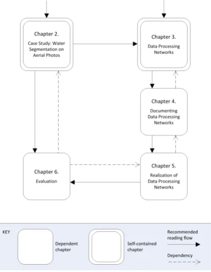
[image:19.595.189.405.400.678.2]An overview of the main chapters can be found in the figure below. The rect-angles present the chapters of this thesis, the solid arrows indicate the rec-ommended reading flow. The reader can start at Chapter 2 or 3, both are self-contained. Chapter 4 should be read before Chapter 5. Chapter 6 is di-vided into two parts. The first part, about the evaluation of the DatProNet framework, depends on Chapter 5. The second part, about the evaluation of the segmentation algorithm, only depends on Chapter 2.
Chapter 2
Case Study: Water
Segmentation on Aerial
Photos
The work presented in this thesis has been carried out to support the CCES project RECORD [10]. The main objective of this project is to investigate the effects of river restoration on the surrounding environment in hydrological, biogeochemical and ecological terms [10]. The CCES project RECORD [10] is focused on a small part of the Swiss river Thur. At their project site the river is monitored by different devices, including two digital cameras. The researchers are interested to see how computer vision algorithms can be used to support the calibration of their environmental models. For this calibration they need a segmented version of the photos taken by the cameras. In this chapter an algorithm is proposed which segments an aerial photo using a water and non-water class.
This chapter is organized as follows. Section 2.1 provides a more detailed de-scription of the actual problem. In section 2.2 an algorithm for the segmentation of aerial photos using a water and non-water class is presented. A conclusion is given after discussing the alternatives and related work in sections 2.3 and 2.4 respectively.
2.1
Problem Description
The CCES project RECORD [10] is aimed at investigating the effects of river restoration on the surrounding environment in hydrological, biogeochemical and ecological terms [10]. Their activities are focused on the river Thur, the largest river in Switzerland without a natural or artificial reservoir [5]. Their field site is located at the restored section at Niederneunforn and Altikon [5]. The river, and the surrounding environment, are analyzed, monitored and observed by different instruments, among them are two digital colour cameras looking
8 Chapter 2. Case Study: Water Segmentation on Aerial Photos
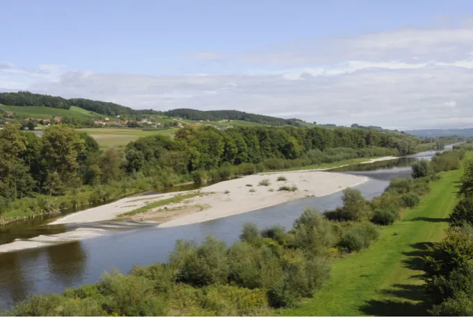
[image:22.595.125.466.216.445.2]or downwards to the river. Pictures are taken every thirty minutes and stored on a computer located at the project site. The researchers are curious to see how computer vision techniques can be used to support their research. As a start, they are interested in the possibilities of using the pictures taken by the cameras for the calibration of their scientific models. For a sample photo taken by the upstream camera, see picture 2.1.
Figure 2.1: Sample photo taken by the upstream camera
The main goal is to develop an algorithm which automatically segments aerial photos using a water and non-water class. The algorithm must be as generic as possible, in other words, it must be easy to apply the algorithm on aerial photos from another natural environment.
2.2
Algorithm for Water Segmenting on Aerial
Photos
Chapter 2. Case Study: Water Segmentation on Aerial Photos 9
2.2.1
Colour-Based Pixel Classification
[image:23.595.114.475.268.361.2]Pixel classification can be done using various techniques which can be cate-gorized into the following two groups: method-based or learning-from-example classification. Using the first technique all the conditional and prior probabil-ities are derived from general knowledge and mathematical models. In case of the learning-from-example approach, the various probabilities are derived from sample objects. Different measurements are done on the sample objects and the gathered data is used to train a classifier. Because the appearance of water is influenced by many factors, which are hard or even impossible to model, the second approach is used.
Figure 2.2: Possible segmentation problems
A perfect aerial photo would contain water with a high contrast and clear bound-ary to its surroundings. Unfortunately this is not always the case, as you can see in picture 2.2. The colour of the water is influenced by many factors. Among them are the depth of the water, the amount of sediment and of course the weather conditions. Pixel classification implies that each pixel is classified in-dividually by a so called classifier. A classifier can be trained in two different ways: supervisedandunsupervised. During supervised learning the related class is known for each sample measurement. This is not the case for unsupervised learning. In our case, the first approach is more suitable because there is no clear distinguishing between water and non-water.
Figure 2.3: Calculation of the minimal-water-area
[image:23.595.125.472.524.623.2]10 Chapter 2. Case Study: Water Segmentation on Aerial Photos
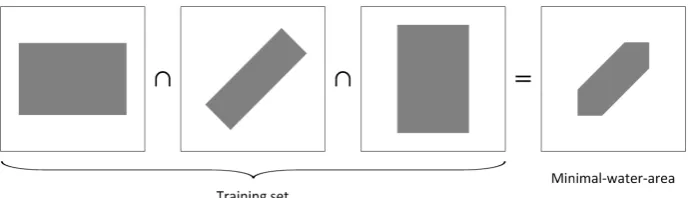
asingle-class classifieris used. In order to extract meaningful training informa-tion from the current picture, some references are needed. To determine useful reference points, a training phase is introduced. During this phase, the algo-rithm is provided with a set of manual segmented photos. From this collection, the minimal-water-area is determined. The minimal-water-area is defined as the intersection of all the water areas inside the trainings photos, see figure 2.3 for an example. To (partially) overcome the problem of human segmentation errors, a configurable margin is used around the borders of the water areas. For the classification, a configurable amount of reference points are used to gather training data. The colour of the water can be quite different inside a single pic-ture, therefore local reference points are used if possible. The gathered colour information is then used by the classifier to classify each pixel, in other words it calculates the probability that a specific pixel belongs to the water class.
2.2.2
Correlation-Based Classification
The second step is aimed at the correlation between pixels inside a single picture. This idea is derived from a filled bowl. If water is detected at the edges of a bowl, we know for sure that there will be water in centre (due to its shape). For aerial pictures, this idea is more complicated since the shape of the river is probably not so regular. Even though this information can be quite useful in combination with the results of the first step. The correlation between the pixels is calculated during the training phase.
The results from the pixel classification step are used to determine reference points. Pixels with a probability above a certain threshold are selected, and their correlated pixels are determined. The correlated pixels are ranked by its correlation factor, which is defined by the number of times it is correlated by another pixel. Pixels below a configurable lower limit are regarded as non-water and pixels above the configurable upper limit are regarded as non-water. All pixels ranked between these boundaries, are submitted for a reclassification. This reclassification is done by a two-class classifier. The classifier is trained with colour information gathered from the already known water and non-water pixels.
After the reclassification, the final result can be determined. Pixels are classified as water if they have a correlation rank above the upper limit or if they are classified as water by the two-class classifier.
2.3
Discussion
Determination of the training set
Chapter 2. Case Study: Water Segmentation on Aerial Photos 11
least one picture with a water level at a certain minimum. Secondly, a picture with a water level at a certain maximum is needed to enlarge the set of possi-ble water pixels. The algorithm only segments those pixels which have bin at least once classified as water during the training phase. By discarding pixels which are definitely non-water, for example the sky, the processing time is de-creased. The lower and upper boundaries of the algorithm are defined by the minimal-water-area and union of all the segmented training pictures.
To ensure the usefulness of the correlation step, a diverse training set is needed. Add as much as possible pictures with various water levels. Be careful with mixing older and more recently taken pictures. The usefulness of the correlation step can decrease dramatically if the shape (or flow) of the river is changing.
Determination of the thresholds
In both steps various configurable thresholds are used. The overall result can be strongly influenced by these values. The (sub)optimal values can be different for each set of aerial photos, and are determined by a trail-and-error technique. Automated determination of optimal thresholds is considered as a possible ex-tension.
2.4
Related Work
A two-stage algorithm for shoreline detection is proposed in [53]. This algorithm starts with classifying the image to one of the following two types: reflection-unidentifiable and reflection-identifiable. For reflection-reflection-unidentifiable images, a thresholding method based on the grey level intensity is used. A line-fitting technique is then used to eliminate outliers. For reflection-identifiable images, a two-class region classifier is used. The image is segmented into small areas based on their colour homogeneity. The areas are then classified by a classifier using the symmetry and brightness characteristics of the areas. In our case, both reflection-unidentifiable and reflection-identifiable images are possible. Unfortu-nately, the appearance of the water (and especially the colour) can have a high overlap with the surrounding nature. A thresholding method based on the grey level intensity is therefore almost useless. Furthermore, the reflections appear-ing inside the CCES project RECORD [10] pictures are not always symmetric and thus makes their reflection based classification less useful.
Algorithms for coastal boundary detection on satellite images can be found in [26, 9]. These algorithms often assume a clear boundary, caused by high contrast in colour. Unfortunately this is not the case for the pictures taken by the two cameras of the CCES project RECORD [10]. Furthermore, the difference with respect to the camera viewpoint makes the methods and techniques proposed in this research topic less useful.
12 Chapter 2. Case Study: Water Segmentation on Aerial Photos
analyzing the appearance of water on a large set of aerial photos. The reflection-cue uses stereo-imaging techniques. The CCES project RECORD [10] does not have access to a stereo based camera set-up and because of the strong weight of this reflection-cue on the final classification the algorithm is less useful at this moment, but it is considered as a possible extension.
2.5
Conclusions
Chapter 3
Data Processing Networks
Recall our definition of a data processing network: a network of computers or (software) components which apply a series of operations on data in order to fulfil a certain task. To support the development of a data processing network by people with limited computer science knowledge, a domain analysis is needed. In this chapter the main concepts and reusable elements of a data processing network are identified, see also sub question number one as defined in section 1.1. These concepts are used to create a basic model and a more specialized model, with respect to implementation and platform alternatives. A clear model will increase the understandability of a data processing network and prevents expensive redesigns.
This chapter is organized as follows. Section 3.1 provides a basic model of data processing networks. In section 3.2 a more specialized model is presented which uses a more detailed representation with respect to implementation and platform alternatives. This specialized model will be used throughout this thesis. A conclusion is given after discussing the alternatives and related work in sections 3.3 and 3.4 respectively.
3.1
Basic Model
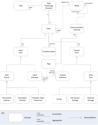
For a good understanding of a data processing network, a basic model is needed. This model identifies the basis concepts and the relations among them. Using our definition of a data processing network, various general concepts are iden-tified which can be found in figure 3.1. Three types of relations are possible: associations,aggregations andgeneralizations. An aggregation indicates a part-whole relationship. Associations and aggregations consists of arole and an op-tional cardinality. For example, the diagram illustrates that a data processing networkfulfils (the role)one or more (the cardinality) tasks, a transformation is part of a filter, and a data source is a specialization of an input port.
There are a few important concepts which need some explanation. A filter, which is deployed on anode, consists of one or moreinput ports, atransformation and one or more output ports. An input port can be a data source, which
14 Chapter 3. Data Processing Networks
Figure 3.1: Data processing networks, a basic model
originates and provides data, or aninput gateway, which provides an entrance to a filter. An output port can be a data sink, which stores data for further use, or an output gateway which provides an entrance to a pipe. Nodes can be connected to other nodes by communication channels. A pipe transmits data from an output gateway to an input gateway using a communication channel.
3.2
Specialized Model
Chapter 3. Data Processing Networks 15
[image:29.595.126.469.217.652.2]Based on our case study, as presented in chapter 2, three extensions of the basic model can be derived. The first extension is a specialization of a data source, called afile system listener, which monitors the file system for changes. A second specialization of a data source is added, called arandom value generator, which can be used for debugging purposes or as a trigger for a specific filter. Thirdly, a specialization of a data sink is created, called file system storage, which stores data packages on the file system.
Figure 3.2: Data processing networks, a specialized model
pro-16 Chapter 3. Data Processing Networks
cessing tasks. Parameters can be put into a configuration file, but sometimes it is easier, and nicer, to ask the user for these constants. A parameter prompt asks the user to fill-in some constants and put them into a single data package.
These data processing networks are all printing there results onto the screen, therefore the concept of a screen is introduced as a specialization of a data sink. Another specialization of a data sink can be derived from the current trend of storing data inside a database using a DataBase Management System (DBMS) like Oracle database [33] or SQL Server [28]. A DBMS controls not only the storage but also the organization, retrieval, security and integrity of data inside a database. Anexternal storagedata sink is created to represent the logic needed to transmit the data to an external storage system like a DBMS.
3.3
Discussion
Decomposition of transformation
In the basic model, and even the specialized model, the transformation is not further specialized. Because the transformation represents the actual processing operation, there are countless specializations possible. With adding specializa-tions of a transformation, the model will be harder to read. In our case the possible benefits of a further decomposed transformation do not outweigh the disadvantages with respect to the understandability of the model.
Data source and data sink specializations
The specialized model contains three data sources and three data sinks. Even though it is possible that another data source or data sink is needed. The specialized model contains commonly used specializations of these concepts, but can be extended if needed.
3.4
Related Work
Chapter 3. Data Processing Networks 17
A model for dataflow process systems is proposed in [23]. Dataflow process systems tend to be a special case of Kahn process networks. The model intro-duces the concept of a dataflow actor and firing rules. When a dataflow actor fires, it will map input to output tokens. The moment of firing is specified by a set of firing rules. These rules specify the input tokens needed for an actor to fire. Once it fires, input tokens are consumed and output tokens are produced. Unlike Kahn processes, dataflow processes can be interleaved by a so called scheduler. This scheduler determines the order in which the various actors can fire. An advantage of these networks is that there is no context switch overhead for the suspension or resumption of a process.
Conventional query processing methods assume a relatively static and pre-dictable computation environment [6]. Unfortunately, these techniques are not sufficient in an constantly changing environment with large streams of continues queries on data streams [6]. The TelegraphCQ [6] query processing system is introduced to overcome these problems. It is focused on its adaptability inside a frequently changing environment.
The past few years a lot of research has been done on the subject of data stream processing. Many of these have led to the development of a so called data stream management system, like Aurora [4]. These systems often use a graphical user-interface to build queries using a set of operators. An overview of the models and issues related to data stream (management) systems can be found in [2, 14, 30].
A software architecture cannot be described in a simple one-dimensional fashion [7]. An architectural description is therefore organized by a set of views. Each view illustrates a specific aspect of the system and supports one or more con-cerns. In [7] a model is presented for documenting a component-and-connector view. One of the specializations of the component-and-connector view, called the pipe-and-filter style, has many similarities with the models presented in the previous sections. The pipe-and-filter style contains definitions of a pipe and filter, but are more high level with respect to their functionality.
A workflow is an automated business process in which documents, information or tasks are processed according a set of rules [8]. A data processing networks is in fact a workflow, but a workflow is not always a data processing network. Workflow systems like Kepler [19] or Taverna [41] are using a very detailed model with respect to the actual transformation, which requires more technical knowledge and increases the complexity of the overall model.
3.5
Conclusions
18 Chapter 3. Data Processing Networks
packages from an output gateway to an input gateway using a communication channel.
Chapter 4
Documenting Data
Processing Networks
Each data processing network has an architecture. Thesoftware architecture of a data processing network consists of the structure or structures of that system, which comprise software elements, the externally visible properties of those, and the relationships among them [3].
A software architecture represents a common abstraction of a system that can be used by people, interested in the construction of the software system, for mutal understanding and communication among them [3]. Between these so called stakeholders, there can be a quite large knowledge gap. In this chapter the data processing style and its specialization theDatProNet style are introduced, which can be used for documenting a data processing network design, see also sub question two as defined in section 1.1.
This chapter is organized as follows. Section 4.1 provides a short introduction about documenting software architectures. In section 4.3 the data processing style is introduced and its specialization, the DatProNet style, is described in section 4.4. Section 4.5 illustrates the usage of the DatProNet style for the CCES project RECORD [10] case study (see chapter 2). A conclusion is given after discussing the alternatives and related work in sections 4.6 and 4.7 respectively.
4.1
Documenting Software Architectures
The software architecture of a system embodies various important design de-cisions, which impacts all the next steps inside the software development life cycle (e.g. development, maintenance, etcetera). It is clear that these decisions must be carefully documented. Software architectures improve the reusability of architectural models between systems with similar functional requirements and/or quality attributes [3].
In the following subsections some basic concepts and techniques are introduced about describing software architectures.
20 Chapter 4. Documenting Data Processing Networks
4.1.1
Software Architecture Descriptions
[image:34.595.125.470.221.643.2]The software architecture of a system is described by a collection of documents called the architectural description. The IEEE 1471 standard, Recommended practice for architectural description of software-intensive systems, [25] is a use-ful guideline for the creation of such an architectural description. This standard introduces a conceptual framework which can be found in the diagram below.
Figure 4.1: The conceptual framework as proposed in IEEE 1471 [25]
op-Chapter 4. Documenting Data Processing Networks 21
tional cardinality. For example, the diagram illustrates that a stakeholderhas (the role) one or more (the cardinality) concerns and that a view is part of an architectural description. There are a few important concepts which need some explanation. Astakeholder is a person or organisation that is interested in the construction of the system. Some typical stakeholders are the end-user(s), software architect, system engineer, developer, designer, etcetera. Each stake-holder has some interests, calledconcerns, in the development, operation or any other critical aspect of the software system. In some cases these concerns are conflicting to each other. Aview consists of a collection of models illustrating a particular aspect of the system. Aviewpoint is a specification for creating and using a particular view.
IEEE 1471 [25] provides a practical guideline for describing software architec-tures. It does not standardize the process of designing an architecture nor the format or notation used for the documentation. In the literature various ar-chitectural design methods or software design processes are proposed, such as, Attribute-Driven Design [3], Model-Driven Design [20] and Rational Unified Process [22]. In practise, UML [37] is often used for describing architectures, but there are also several specific architecture description languages (ADLs) proposed in the literature, such as, Aesop [13], Darwin [24] and Weaves [15].
4.1.2
Software Architecture Views
[image:35.595.212.377.542.698.2]A software architecture cannot be described in a simple one-dimensional fash-ion [7]. An architectural descriptfash-ion is therefore organized by a set of views. Each view illustrates a specific aspect of the system and supports one or more concerns. In the literature some authors have proposed fixed sets of views to document a software architecture. For example, Kruchten’s 4+1 view approach [21] introduces a logical view, a development view, a process view and a phys-ical view. On the other hand the current trend is more like taking different sets of views for different systems instead of a fixed set for all software systems. The IEEE 1471 standard has taken this trend into account by just proposing a multi-view approach and not a particular set of views.
22 Chapter 4. Documenting Data Processing Networks
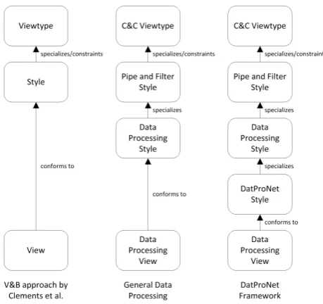
In the literature many different views can be found. Clements et al. proposed their Views and Beyond (V&B) approach [7] to bring some order to all these views. They basically split the viewpoint concept into a viewtype and a style (see figure 4.2). A viewtype defines the elements and their possible relation-ships which can be used to describe the system from a particular perspective [7]. A style specializes the elements and relationships defined by a viewtype and adds some (additional) constrains on their usage [7]. The V&B approach introduces three different viewtypes: the module viewtype, the component-and-connector viewtype and the allocation viewtype. Furthermore they introduce different specializations, for example, thepipe-and-filter styleis a specialization of the component-and-connector viewtype. The concept of viewtypes and styles makes the V&B approach easy adaptable since an architect can define any style needed.
4.2
The Need for a Domain-Specific View
Data processing networks are used in many different domains. The scientific research domain is just one of them. During the development of a data process-ing network, there can be a quite large knowledge gap between the developers and the researchers. They are mainly interested in how the data flows and less about how this is achieved. Therefore it is important to have a specializeddata processing view which can be easily understood by all interested stakeholders.
[image:36.595.179.409.483.699.2]The IEEE 1471 standard proposed a multi-view approach but it does not intro-duces any specific views. The V&B approach introintro-duces various different styles which can be used for documenting a software architecture. One of the styles they propose is the pipe-and-filter style which is often used for documenting data transformation systems.
Chapter 4. Documenting Data Processing Networks 23
In the next section, a data processing style is proposed which specializes the elements and relations of the pipe-and-filter style. To document data processing networks represented by the specialized model from section 3.2, another style is created, called the DatProNet style, in which the elements and relations of the data processing style are further specialized (see figure 4.3).
4.3
Data Processing Style
[image:37.595.151.443.293.454.2]The data processing style can be used for documenting adata processing view. The notation for the key concepts from the basic model (see section 3.1) can be found in figure 4.4. For notation purposes only, the concept of a binding is added.
Figure 4.4: Data processing style notation
Elements: Filter. Filter ports must be either input (light coloured) or output (dark coloured) ports. An input port can be an input gateway or a data source. An output port can be an output gateway or a data sink.
Relations: Binding, Pipe.
Properties of elements: Properties of a Filter: a name which suggest its functionality, a description indicating its place inside the data processing network, one or more input ports and one or more output ports.
Properties of relations: Properties of a Pipe: type of communication (for example synchronous or a-synchronous).
24 Chapter 4. Documenting Data Processing Networks
The DatProNet style introduces the filter element with different kinds of input and output ports. Data packages are arriving through the input ports. Inside the filter there will be some data transformation applied onto the packages. Data packages are leaving the filter through its output ports. Input gateways are just passing data packages from a binding or pipe to the filter. Data sources are originating and providing data to the filter. Output gateways are passing data packages from the filter to a binding or pipe. Data sinks store data packages for further use. A binding can only be used to connect two filters placed inside of each other. A pipe is used for the communication between two filters. Each pipe uses its own type of communications and has its own quality properties (in the sense of recoverability, performance, etcetera).
4.4
DatProNet Style
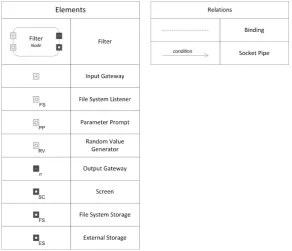
[image:38.595.151.444.369.620.2]In this section, the DatProNet style is presented in which the elements and relations of the data processing style are further specialized according to the specialized model as introduced in section 3.2. The key elements and relations can be found in figure 4.5.
Figure 4.5: DatProNet style notation
Chapter 4. Documenting Data Processing Networks 25
Relations: Binding, Socket Pipe.
Properties of elements: Properties of a Filter: a name which suggest its functionality, a description which suggest its place inside the data pro-cessing network, one or more input ports and one or more output ports. Properties of a File System Listener: the element (directory or file) it lis-tens to and some performance based properties (e.g. delay between two polling sessions, minimal delay between the generation of two data pack-ages, etcetera). Properties of a Parameter Prompt: a set of parameters which has to be provided (manually) by the user and the type of commu-nication used (for example command-line). Properties of a Random Value Generator: a range specifying the possible values it can generate and some performance based properties (same as File System Listener). Properties of an Output Gateway: a number indicating the amount of pipes which will be selected (randomly) to pass an incoming data package on. Proper-ties of a File System Storage: a directory indicating the location where the packages will be stored. Properties of an External Storage: a description of the external application used for storing the incoming data packages.
Properties of relations: Properties of a Socket Pipe: the port number used for the socket communication and an optional condition indicating in which cases the pipe accepts data packages.
Topology: A pipe connects an output gateway to an input gateway. A binding connects an input port to an input gateway or connects an output gateway to an output port. Bindings can only be used inside a filter. Every input and output gateway should be connected using these rules. Filters can be placed inside each other using the binding relation and the rules above. Each set of connected filters should contain at least one filter with a data source input port and one filter with a data sink output port (can be combined in a single filter).
4.5
Using the DatProNet Style
Figure 4.6 illustrates the usage of the DatProNet style for documenting a data processing view for the CCES project RECORD [10] case study. A description of the CCES project RECORD case study can be found in chapter 2.
The figure illustrates just one possible data processing view. Many alternatives are possible. One of them would be to remove the specializations of the training and analyze filter. Some computer vision details are lost but depending on the interested stakeholders, it could be a valid choice.
26 Chapter 4. Documenting Data Processing Networks
Figure 4.6: A data processing view for the CCES project RECORD [10] case study (for key see figure 4.5)
4.6
Discussion
Style or Viewpoint?
The data processing style is a specialization of the pipe-and-filter style intro-duced by the V&B approach [7]. The V&B approach does not describe the concept of a viewpoint, as defined by the IEEE 1471 standard [25], however it introduces the viewtypes and styles. A viewpoint describes the language and notation used to create a particular view. Therefore the data processing style, and also the DatProNet style, can be considered as a viewpoint as well since both styles define a notation to describe a data processing view. Because both styles are strongly related to the component-and-connector viewtype and the pipe-and-filter style, the terminology of the V&B approach is selected.
Data Flow Views
Chapter 4. Documenting Data Processing Networks 27
Static and dynamic analysis
Static analysis can support the user with the development of a faultless data processing network. Static analysis contains at least a verification of the topol-ogy requirements as stated in the previous sections. But even after performing this verification, it is still possible to develop a data processing network con-taining one or more faults. For example, if a data processing view contains a loop, it is impossible to verify (with static analysis) that a specific data package eventually will arrive at a data sink output port. With dynamic analysis more verification can be done. For example, a verification of the performance prop-erties of the various input ports (together with a suggestion of their optimal values). Other possibilities of applying static and dynamic analysis on a data processing view is considered as feature work.
4.7
Related Work
In [18] UML 2.0 is discussed as a language/notation for documenting software architectures and in particular component-and-connector views. With respect to earlier versions of UML there is some improvement but still its not possible to represent connectors (the pipes) in an intuitive way.
A comparison of architectural styles for network-based software architectures can be found in [11]. After a classification and comparison of the existing styles, theRepresentational State Transfer (REST) style for distributed hyper-media systems is introduced. In comparison with the data processing style, and also the DatProNet style, the REST style is more focused on the network prop-erties instead of the data processing aspects. Depending on the interest of the stakeholders, both styles can be used inside an architectural description.
Workflows can be created with a Workflow Management Systems like Kepler [19] or Taverna [41] using an intuitive drag-and-drop interface. A workflow is defined as the automation of a business process, in whole or part, during which documents, information or tasks are passed from one participant to another for action, according to a set of procedural rules [8]. A data processing network is in fact a workflow, but a workflow is not always a data processing network. The workflows created by these systems support some decentralization aspects, but there is always a central system needed to execute the workflow, so it is not completely decentralized. In comparison with the data processing style, the workflows created by Kepler [19] or Taverna [41] offer a more detailed view on the processing task, especially on how the transformation is done. De data processing style, and even the DatProNet style, are more high level and thus require less knowledge about the application.
4.8
Conclusions
pipe-28 Chapter 4. Documenting Data Processing Networks
Chapter 5
Realization of Data
Processing Networks
In the previous chapter the data processing style and its specialization, the DatProNet style, where introduced. After designing, documenting and ana-lyzing the architecture of a data processing network, the various architectural elements and relations should be implemented. In this chapter the DatProNet framework is introduced to reduce the development and maintenance effort of a data processing network, see also sub question number three as defined in section 1.1.
This chapter is organized as follows. Section 5.1 provides an outline of the basic requirements. In section 5.2, the DatProNet framework is introduced. Section 5.3 discusses the extensibility of the DatProNet framework. Section 5.4 illustrates the usage of the DatProNet framework for the CCES project RECORD [10] case study (see chapter 2). A conclusion is given after discussing the alternatives and related work in sections 5.5 and 5.6 respectively.
5.1
Basic Requirements
The development of a data processing network imposes certain requirements to its architecture. Based on our models from chapter 3 and the CCES project RECORD [10] case study (see chapter 2), the following requirements are iden-tified (sorted by importance):
Reliability: A data package flowing through a data processing network may never be lost, not even during any kind of system failure.
Ease of use: People with limited computer science knowledge should be able to develop, and maintain, a data processing network through the framework.
Interoperability: A typical data processing network uses various exter-nal applications to perform the processing steps. The framework should
30 Chapter 5. Realization of Data Processing Networks
provide a way to communicate (bi-directional) with these applications pre-serving the requirements and quality aspects denoted.
Portability: The framework should support various system environments. It should be possible to develop data processing networks which can be deployed on a Windows [29], Linux (e.g. RedHat Linux [36]) or Unix (e.g. FreeBSD [12]) based platform. Furthermore it should support the possibility of having various system environments inside one specific data processing network.
Recoverability: In case of a system failure (hardware or software) the data processing network should be able to recover from this event and return to a consistent state. The framework must be captured to deal with unavailability of nodes, for example, by sending retrying messages or by generating exceptions.
Extensibility: It should be possible to extend the framework with cus-tomized input or output ports, transformations and/or pipes. In this way each user can customize the framework to its own special needs without having to develop a complete data processing network from scratch.
5.2
DatProNet: A Framework for the
Realiza-tion of Data Processing Networks
To reduce the development and maintenance effort of a data processing network, the DatProNet framework is introduced. The framework has been implemented in the JAVA language [32]. Through the concept of write-once-run-anywhere [50], a variety of platforms are supported. The DatProNet framework comprises a collection of reusable components and an architecture description language, both items are discussed in the following subsections.
[image:44.595.125.471.612.689.2]The development life cycle of a data processing network is illustrated in figure 5.1. Once a data processing view is created, it can be mapped to an architectural description using the DatProNet language. This architectural description can be put into the DatProNet framework which creates the required deployment packages for the various machines. Each deployment package can only be used on the machine it is created for.
Chapter 5. Realization of Data Processing Networks 31
5.2.1
Reusable Components
[image:45.595.124.471.245.700.2]The frameworks includes a set of reusable abstractions for data processing net-works. Figure 5.2 shows a conceptual view of the DatProNet framework as an UML class diagram [44]. The framework comprises eight main components: Fil-ter,InputPort,OutputPort, Transformation,Condition, PipeEnd,DataPackage andSerializer. Using these reusable components, the DatProNet framework can be easily extended. Section 5.3 provides more information about extending the DatProNet framework with user-defined components.
32 Chapter 5. Realization of Data Processing Networks
Each node inside a data processing network is mapped onto aFilter. EachFilter connects the relatedInputPortsto theTransformation, and theTransformation to the relatedOutputPorts. A data package flowing through the data processing network is encapsulated by a DataPackage which contains a list of data items and a list of related resources. A pipe is divided into two parts (so called PipeEnds): aSource and aDestination.
DataPackages are generated by DataSources. Each data processing network must contain at least one DataSource. The framework contains three prede-fined DataSources: one that monitors the file system for changes, one that generates DataPackages with a random value and one that asks the user for some additional input. Other DataSources can be developed by implement-ing DataSource. InputGateways are passing DataPackages from a Destination PipeEnd to the related Transformation.
Once the DataPackages are arrived at the Transformation, various operations are possible. The framework contains four predefined transformations. The first transformation applies a Cross-Join operation on the incoming DataPackages. The second one provides the possibility of adding and removing data items in-side a DataPackage. The third transformation can be used for (bi-directional) communication with an external application. The last one is an empty trans-formation, it just passes the DataPackages without any transformation. Other transformations can be developed by implementing Transformation.
OutputGateways are passing DataPackages from the Transformation to the con-nected Source PipeEnds. By default, incoming DataPackages are put on all the connected, and activated through Condition, Source PipeEnds. The Random specialization selects randomly a specific number of connected, and activated, Source PipeEnds. DataPackages can be stored by DataSinks using a specific Serializer. The framework contains three predefined DataSink implementations: one for storing the DataPackages onto the file system, one for external storage and one for showing incoming DataPackages onto the screen. Other DataSinks can be developed by implementing DataSink.
A Serializer can be used for converting DataPackages to any other format. The framework contains a MATSerializer which can be used for serializing Data-Packages to a MatLab-readable format [42]. Serializers for other applications or formats can be developed by implementing Serializer.
The InputPort, Transformation, OutputPort and PipeEnd components use an acknowledge based method to communicate to each other. In this way a reliable data processing network can be created. Furthermore, The PipeEnd compo-nents are using a polling technique to recover from unavailable nodes inside the data processing network.
5.2.2
Architecture Description Language
Chapter 5. Realization of Data Processing Networks 33
XML Notepad [27]. With this architecture description language all the fea-tures of the DatProNet framework can be configured. An architectural de-scription consists of various components, and all these components are defined by XML-tags. When we refer to an XML-tag including its contents, we call it an XML-element. An XML-element thus includes all enclosed XML-tags and XML-elements. An XML-tag consist of a keyword enclosed by the brack-ets ’<’ and ’>’. The DatProNet language is strongly structured and consists of a root element called<project>, which contains a<filters>element. The <filters>element consists of a set of<filter>elements. A<filter>element has three sub elements: an<input>element, a<transformation>element and an<output>element.
1 < project > 2 < filters >
3 < f i l t e r n a m e =" S a m p l e F i l t e r " r u n a t = " 1 2 7 . 0 . 0 . 1 " b u f f e r ="10" >
4 < input >
5 ...
6 </ input >
7 < t r a n s f o r m a t i o n >
8 ...
9 </ t r a n s f o r m a t i o n > 10 < output >
11 ...
12 </ output > 13 </ filter > 14 </ filters > 15 </ project >
Listing 5.1: The basic structure of an architectural description
The<filter>element has three attributes: name,runatandbuffer(optional). The first attribute depicts its name and must be unique. The second attribute shows the ip-address of the machine where the filter will be deployed on. The last attribute indicates the maximum number of DataPackages inside the internal buffer. In the following subsubsections the three sub elements of the<filter> element are discussed.
The <input> element
The <input> element consists of a set of <port> elements. Each <port> element has two attributes: name and type. The name must be unique inside the parent <input> element. Four types of InputPorts are defined: gateway, filesystemlistener,parameterpromptandrandomvaluegenerator. The first type has no aditional sub elements and just passes the incoming DataPackages to the related Transformation. The other three types have their own set of sub elements.
34 Chapter 5. Realization of Data Processing Networks
modified files are put into a DataPackage. The file or directory can be specified by the<object>element. In the case of a directory, no subdirectories are taken into account by default, if needed they can be set by the <depth> element. Three operational modes are possible in case of a directory: all, collection and single, which can be specified by the <mode> element. When single is selected, only the modified file is put into a DataPackage. In case of multiple modified files, each file is put into a separate DataPackage. Whencollection is selected, all the modified files are put into one single DataPackage. When the option all is selected, the complete contents of the directory is put into one single DataPackage. The <key> element is used to define the name for the entries inside the DataPackage. With the<initialization>element, the start-up procedure can be defined. Two types of initialization are possible: clear (default) or current. When clear is selected, the file or all the files inside the directory are said to be modified at start-up. When current is selected, the modification time of the file or the contents of the directory is stored at start-up and used for the next check. With the optional <delay> and<lifetime>elements, the delay between two checks and the lifetime of the generated DataPackages can be set (milliseconds).
1 < p o r t n a m e =" I n p u t " t y p e =" f i l e s y s t e m l i s t e n e r " > 2 < object > C :\ i m a g e s \ </ object >
3 < depth >1 </ depth >
4 < key > c o n f i g u r a t i o n </ key >
5 < i n i t i a l i z a t i o n > clear </ i n i t i a l i z a t i o n > 6 < mode > single </ mode >
7 < delay >700 </ delay >
8 < l i f e t i m e >700 </ l i f e t i m e > 9 </ port >
Listing 5.2: An InputPort of typefilesystemlistener
A parameterprompt InputPort asks the user to provide some additional in-put. These parameters can be defined through the <parameters> tag. The <parameters> tag consists of one or more<parameter>tags. A<parameter> tag consists of the following tags: a<key>tag indicating its name inside a Data-Package, a<title>tag indicating the title of the parameter (will be shown to the user) and a <type> tag indicating the parameter type. Possible types are boolean,file,float,integer, andstring.
1 < p o r t n a m e =" I n p u t " t y p e =" p a r a m e t e r p r o m p t " > 2 < p a r a m e t e r s >
3 < p a r a m e t e r >
4 < key > Count </ key >
5 < title > N u m b e r of loops </ title > 6 < type > integer </ type >
7 </ p a r a m e t e r > 8 </ p a r a m e t e r s > 9 </ port >
Chapter 5. Realization of Data Processing Networks 35
A randomvaluegenerator InputPort generates DataPackages with a pseudo-random integer value inside. This can be useful for debugging purposes or to trigger another filter. The range can be defined using the<min>(inclusive) and <max> (exclusive) elements. The<key> element is used to define the name for the entry inside the DataPackage. With the optional<delay>and<lifetime> elements, the delay between the generation of two DataPackages and their life-time can be set.
1 < p o r t n a m e =" I n p u t " t y p e =" r a n d o m v a l u e g e n e r a t o r " > 2 < min >0 </ min >
3 < max >100 </ max > 4 < key > trigger </ key > 5 < delay >700 </ delay >
6 < l i f e t i m e >700 </ l i f e t i m e > 7 </ port >
Listing 5.4: An InputPort of typerandomvaluegenerator
The <transformation> element
A<transformation>element has only one attribute indicating its type. There are four types of Transformations possible: empty,external,joinandreform. TheemptyTransformation does not apply any transformation onto the incoming DataPackages. The other three types can be configured by their own set of sub elements.
Anexternal Transformation passes DataPackages to an external application. The external application can be defined by the<command>element. Parameters can be passed through the <parameters> element which consists of a set of <parameter>elements. The value of the<parameter>element may contain%f and%dmarkers which are substituted for the temporary DataPackage filename and directory respectively. With the<serializer>element, the required Seri-alizer can be selected. The DatProNet framework contains only one predefined serializer. This matlab serializer can be used to convert a DataPackage to a Matlab-readable format [42]. To prevent endless waiting, a timeout can be set with the optional <timeout>element. The default value is set to 60 seconds. In case the timeout expires, an exception will be thrown. The exit value can be defined by the optional<exitvalue>element (default 0). When the current exit value differs from the configured one, an exception will be thrown.
1 < t r a n s f o r m a t i o n t y p e =" e x t e r n a l " > 2 < command > m a t l a b . exe </ command > 3 < p a r a m e t e r s >
4 < p a r a m e t e r > - n o d e s k t o p </ p a r a m e t e r > 5 < p a r a m e t e r > - wait </ p a r a m e t e r > 6 < p a r a m e t e r > - r </ p a r a m e t e r >
36 Chapter 5. Realization of Data Processing Networks
8 </ p a r a m e t e r s >
9 < s e r i a l i z e r > matlab </ s e r i a l i z e r > 10 < timeout > 3 6 0 0 0 0 0 < / timeout > 11 < e x i t v a l u e >0 </ e x i t v a l u e > 12 </ t r a n s f o r m a t i o n >
Listing 5.5: A Transformation of type external
A join Transformation applies a cross-join operation on the incoming Data-Packages. For each connected InputPort, a separate buffer is created. If a DataPackage is arriving through an InputPort, it is joined with all the Data-Packages inside the other buffers. DataData-Packages stay in their buffer until they expire (by their lifetime) or when the buffer reach its capacity, which can be defined by the <capacity> element. When the maximum capacity is reached, DataPackages are removed using the first in - first out principle.
1 < t r a n s f o r m a t i o n t y p e =" j o i n " > 2 < c a p a c i t y >100 </ min >
3 </ t r a n s f o r m a t i o n >
Listing 5.6: A Transformation of type join
A reform Transformation can be used for adding or removing data entries to or from a DataPackage. The reform Transformation can be used for example to create a looping mechanism inside a data processing network. The required <packages> element consists of a set of <package> elements. A <package> element contains a set of <addfield> and<removefield> elements. The first element, <addfield>, can have two attributes: keyand override (optional). Thekeyattribute indicates the name of the (new) entry, andoverrideindicates if an existing key may be overwritten by its new value. The<removefield>has only one attribute: thekeyof the entry that must be removed. If n <package> elements are defined, each incoming DataPackage will result innoutgoing Data-Packages.
1 < t r a n s f o r m a t i o n t y p e =" r e f o r m " > 2 < p a c k a g e s >
3 < a d d f i e l d key =" x " o v e r r i d e =" f a l s e " >0 </ a d d f i e l d > 4 < r e m o v e f i e l d key =" y " / >
5 </ p a c k a g e s > 6 </ t r a n s f o r m a t i o n >
Listing 5.7: A Transformation of type reform
The <output> element
Chapter 5. Realization of Data Processing Networks 37
own set of sub elements, the screen type just prints the contents of a Data-Package onto the screen and requires no further configuration.
AgatewayOutputPort passes incoming DataPackages onto the connected, and activated, pipes. The related pipes can be defined through the<pipes>element. The optional activation rules can be defined through the<conditions>element. The <conditions> element consists of a set of <condition> elements. The <condition> element has one attribute indicating its name which must by unique inside its parent <conditions> element. The <condition> element contains a boolean value tag, like <true>or<false>, or a boolean determina-tion tag, like<match>or<time>, or a boolean operator tag, like<and>,<or>or <not>, or a reference to another <condition>tag using the<reference> tag. The <and>, <or> and<not> elements behave like the boolean operations and, or and not and consist of at least one sub tag (boolean value, determinator, operator or reference).
The<match>element can be used to match a DataPackage by its contents. It can be configured by a <key> and/or <value> element. If only the <key> element is defined, the <match> element returns true when an entry with the value of the <key> element is defined inside the DataPackage. If only the <value> element is defined, the <match> element returns true when the DataPackage contains an entry with a value equal to the value of the <value> element. If both elements,<key>and<value>, are defined, the<match>element returnstrueif this combination exists inside the DataPackage.
Character Description Example
d Day of the month, 2 digits with
leading zeros
01 to 31
j Day of the month without leading
zeros
1 to 31
N ISO-8601 numeric representation of
the day of the week
1 (for Monday) through 7 (for Sunday)
z The day of the year (starting from 0) 0 through 365
m Numeric representation of a month,
with leading zeros
01 through 12
M Numeric representation of a month,
without leading zeros
1 through 12
W ISO-8601 week number of year, weeks
starting on Monday
42 (the 42nd week in the year)
y A two digit representation of a year 99 or 10
Y A full numeric representation of a
year, 4 digits
1999 or 2010
h 12-hour format of an hour with
leading zeros
01 through 12
H 24-hour format of an hour with
l

![Figure 4.1: The conceptual framework as proposed in IEEE 1471 [25]](https://thumb-us.123doks.com/thumbv2/123dok_us/1197798.643125/34.595.125.470.221.643/figure-conceptual-framework-proposed-ieee.webp)