University of Twente
EEMCS / Electrical Engineering
Robotics
and
Mechatronics
Modeling and Magnetic-Based Motion
Control of a Cluster of Microparticles
F. (Frank) van den Brink
BSc Report
Committee:
Dr. S. Misra Dr. I.S.M. Khalil Dr.ir. L. Abelmann Dr.ir. J. Flokstra
January 2013
Introduction
This bachelor thesis focuses on the modeling and control of a cluster of micro particles. The cluster of micro particles is used to perform point-to-point motion control experiments with and without micro-objects. Further, the cluster of micro particles is used to investigate the feasibility of using micro particles for wireless micro assembly applications. In this bachelor thesis, the following tasks are completed:
1. Investigation of the optimal cluster size within the work space of our mag-netic system. This investigation was done by pulling several cluster sizes under a constant magnetic field gradient and comparing their velocities
2. Modeling of a cluster of micro particles. This modeling includes calcula-tion of the contours of the clusters of micro particles
3. Design of micro-objects and a target structure
4. Investigation of the feasibility of using a cluster of micro particles to ac-complish wireless micro assembly.
These tasks are explained in the remainder of this thesis. The magnetic system and the control software used to perform the motion control experiments were already developed before this assignment started [15], [17], [28].
Contributions
The results of this thesis contributed to the following paper:
I. S. M. Khalil, F. van den Brink, O. S Sukas, L. Abelmann, and S. Misra, “Microassembly using a cluster of microparticles,” inProceedings of the IEEE International Conference on Robotics and Automation (ICRA), Karlsruhe, Ger-many, May 2013,In Press.
Modeling and Magnetic-Based Motion Control
of a Cluster of Micro Particles
Frank van den Brink, Islam S. M. Khalil and Sarthak Misra
University of Twente, The Netherlands
Abstract— We investigate a dynamic model for a cluster of micro particles inside a fluid under the influence of magnetic fields. The drag force of a cluster of micro particles is modeled by estimating its geometry using an ellipsoid with an axis ratio of 8. Point-to-point motion control experiments with a cluster of micro particles are carried out with a maximum average velocity of 327µm/s, and maximum position tracking error of 110 µm/s. Our magnetic system has a workspace of 1.8 mm × 2.4 mm, and is capable of generating magnetic field and gradient of the magnetic field squared of 5 mT and 0.4 T2/m, respectively. In order to investigate the feasibility of performing micro assembly tasks using micro particles, a cluster of micro particles is utilized to perform micro manipulation of micro-objects and direct these micro-objects into destinations within a target structure. Micro manipulation experiments are executed with a maximum average velocity and maximum position tracking error of 297µm/s and 150µm respectively. Micro assembly of micro objects using a cluster of micro particles is demonstrated at an average velocity of 193µm/s and an execution time of 18 s.
I. INTRODUCTION
[image:4.612.329.540.172.330.2]Motivated by the continuous demand for miniaturization in modern technology [1], new micro assembly and mi-cro manipulation techniques have been developed [2]-[7]. Magnetic systems are utilized to control micro particles and magnetotactic bacteria. Applications of these controlled micro particles and bacteria are in the field of minimally invasive surgery (MIS) [8] and micro assembly [9]. Micro as-sembly using a swarm of magnetotactic bacteria is achieved by Martel et al. [10]. A swarm of approximately 5000 bacteria constructed a miniature step pyramid in ∼15 min-utes. Assembly by microrobots is realized by Fatikow et al. [11], [12]. These micro robots are 50 mm to 80 mm in length, and achieve a resolution down to 10 nm and velocities up to 30 mm/s. In the field of MIS, electromagnetic systems have been used to control micro particles [8]. These micro particles can perform targeted drug delivery [13]. Electromagnetic systems can steer the micro particles to hard-to-reach regions within the human body. Utilization of micro particles as drug carriers could reduce negative side effects as the drug can be delivered locally without affecting the healthy tissue [13]. The magnetic force applied on a micro particle depends on its size. Therefore, each micro particle experiences a magnetic force in the range of few nanoNewton to tens of nanoNewton. In this thesis, we focus on utilizing micro particles for micro assembly. We use a cluster of micro particles to increase the magnetic force with a factor of approximately 20. The cluster of micro particles is used to push and/or pull micro objects towards selected
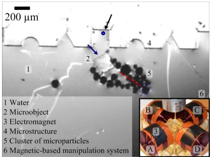
Fig. 1. Magnetic-based micro assembly operation: the cluster of micro particles (5) pushes the micro object (blue arrow) into the micro structure (4) by moving towards a given reference position (black arrow). The external magnetic fields are generated by 4 orthogonal electromagnets, as shown in the inset. The electromagnets surround a fluid reservoir which contains the cluster of micro particles, the micro-object and the target structure. The blue circle and the red line are assigned by our feature tracking software [28]. They represent the position and the velocity of the cluster, respectively.
destinations within a target structure (Fig. 1). This is done to investigate the feasibility of employing a cluster of micro particles to perform wireless magnetic-based micro assembly. The following tasks are carried out:
1) Investigation of the optimal cluster size within the workspace of our magnetic system
2) Modeling of the cluster of micro particles 3) Design of the motion control system
4) Point-to-point motion control experiments of the clus-ter of micro particles
II. MODELING AND CONTROL
A cluster of micro particles experiences a magnetic force and torque under an applied magnetic field. The magnetic force and torque must overcome the drag force and torque to allow the cluster to move inside a fluid. In this section, we discuss the modeling of the drag force and torque and the magnetic force and torque. In addition motion control of a cluster of micro particles is addressed.
A. Magnetic Force Modeling
The magnetic force F(P)∈R3×1 on a micro particle is
given by [14]
F(P) =∇(m(P)·B(P)), (1) wherem(P)∈R3×1 is the permanent or induced magnetic
dipole moment of the micro particle andB(P)∈R3×1is the
induced magnetic field at point (P∈R3×1). The permanent
or induced magnetic dipole moment is
m(P) =αpVpB(P), (2)
where Vp is the volume of the micro particle, and αp is a
magnetic constant, and is given by
αp=
χm
µ , (3)
where χm is the magnetic susceptibility constant and µ is
the permeability coefficient, and is given by
µ=µ0(1 +χm). (4)
In our magnetic system,αp=185 kA2N−1[15]. Substituting
(2) in (1) yields
F(P) =αp
4 3πr
3 p∇(B
T(P)B(P)),
(5) whererp is the radius of a micro particle. We assume that
the magnetic force on a cluster of micro particles is the sum of the magnetic force on theith micro particle
Fc(P) =
n X
i=1
Fi(P), (6)
wherenis the number of micro particles within the cluster, andFi(P)is the force experienced by theith micro particle.
The magnetic torque on a micro particle is zero, therefore we can not assume that the magnetic torque on a cluster of micro particles is the sum of the magnetic torque on the
ith micro particle. The magnetic torque experienced by the cluster of micro particles is given by
T(P) =mc(P)×B(P), (7)
whereT(P)∈R3×1 is the magnetic torque andm c(P)∈
R3×1 is the permanent or induced magnetic dipole moment
of the cluster.
The magnetic force should overcome the drag force to move the cluster of micro particles. In order to calculate the drag force, it is important to know whether the micro particles move in a low Reynolds number regime. Reynolds
number is the ratio between inertial forces and viscous drag forces. Laminar flow for a single micro particle can be assumed when the Reynolds number of the micro particle is less than 0.1. The Reynolds number of a micro particle is given by [15]
Re= 2ρfvrp
η , (8)
where v, η and ρf are the micro particle velocity, fluid
dynamic viscosity (1 mPa.s) and density (998.2 kg/m3), respectively. At a linear velocity of 500µm/s, the Reynolds number is 0.0498. Therefore, laminar flow can be assumed and Stokes’ law can be applied for the drag force
Fd(P˙) = 6πηrpP˙, (9)
whereFd(P˙)∈R3×1 is the drag force on a micro particle.
A cluster of micro particles experiences a drag force given by
Fdc(P˙) =zcηP˙, (10)
whereFdc(P˙)∈R3×1 is the drag force on the cluster, and zc is the shape factor for drag of the cluster. This shape
factor zc is based on the geometry, area and size of the
cluster. For micro assembly applications, a micro-object has to be steered towards a targetstructure. The drag force of the micro-object is given by
Fdo(P˙) =zoηP˙, (11)
whereFdo(P˙)∈R3×1is the drag force on the micro-object,
andzois the shape factor for drag of the micro-object. The
drag force of the micro-object depends on its geometry. The size of the micro-objects is small relative to the size of the cluster of micro particles. Therefore the drag force on the micro-object is assumed to be nelligible. We assume that a cluster of micro particles has a similar geometry to a disc, and therefore the shape factorzc is estimated by [16]
zc=
32a
3 , (12)
whereais the radius of the disc. Assuming that the area of the disc is the sum of the area of the micro particles, the radius of the disc is given by
a=√n rp (13)
Substituting (12) and (13) in (10) yields the following equation for the drag force of a cluster of micro particles:
Fdc(P˙) =
32√n rp
3 η
˙
P. (14)
The drag torque is given by
Td(ω) =αω, (15)
(a) (b)
Fig. 2. The effect of an external magnetic field of 4 mT on the shape of a cluster of micro particles. (a) The shape of a cluster of micro particles in the absence of a magnetic field. In this case, the micro particles are not magnetized and adhesive forces dominate. (b) The shape of the same cluster of micro particles after the application of a magnetic field. In this case the micro particles are magnetized and magnetic forces dominate, and a cluster is formed.
of micro particles is estimated by (8), (9) and (14). Rewriting (8) yields
Re= Ωp
ρfv
η , (16)
where Ωp is the shape factor for Reynolds number of the
micro particle and is given by Ωp = 2rp. The Reynolds
number for a cluster of micro particles is given by:
Rec = Ωc
ρfv
η , (17)
where Ωc is the shape factor for Reynolds number of the
cluster of micro particles. Rewriting (9)
Fd(P˙) =zpηP˙, (18)
where zp is the shape factor for drag of a micro particle.
The shape factor for Reynolds number of a cluster of micro particles is estimated by calculating the ratio between the shape factor for drag and the shape factor for Reynolds number. We calculate this ratio for a single micro particle and equate it to the ratio for a cluster of micro particles
zp
Ωp
= zc Ωc
. (19)
Using (12) and (19) yields
Ωc=
32√nrp
9π , (20)
which gives the following Reynolds number for a cluster of micro particles
Rec=
32√nrpρfv
9πη . (21)
Inertial forces have to be included in the equation of motion when the Reynolds number of the cluster is larger than 0.1. We observe that the shape of a cluster of micro particles varies with the magnetic field. Therefore the shape factor for dragzc and the shape factor for Reynolds number
Ωc are not constant. In the absence of a magnetic field, the
[image:6.612.68.299.63.144.2]micro particles have negligible magnetization since they are paramagnetic. Adhesive forces between the micro particles dominate. After the application of a magnetic field, the
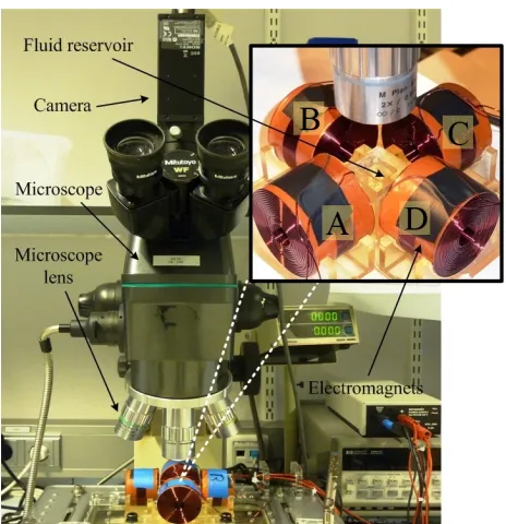
Fig. 3. Magnetic system for the manipulation of micro particles and assembly of micro-objects. The magnetic system consists of four orthogonal electromagnets with a microscope and a vision system [28]. The inset shows the four electromagnets surrounding a fluid reservoir filled with water. The letters A, B, C and D represent the electromagnets.
micro particles become magnetic and hence, magnetic forces dominate their behavior. Figs. 2(a) and (b) show the shape of a cluster of micro particles in the absence and presence of a magnetic field, respectively. Due to the change in shape of the cluster of micro particles, the drag force and Reynolds number vary. Compensation of the drag force will be explained in Section II-E.
B. Field Current Map
In order to represent the magnetic field as a function of the currents, a field-current map is realized. The relation between the current through an electromagnet and the magnetic field produced by this electromagnet is linear [7], [17]. Therefore, the magnetic field of theeth electromagnet can be written as
Be(P) =Bee(P)ie, (22)
where Bee(P) ∈ R3×m is the magnetic field map and m is the number of electromagnets. The map Bee(P) is
defined at each point (P) of the workspace of our magnetic system (Fig. 3).Bee(P)can be determined by measuring the
magnetic field Be(P)at each point within the workspace
of our magnetic system. We divide the measured magnetic field Be(P) by the applied current (ie) to calculate the
magnetic field map Bee(P). Due to linearity of our field
current map (22), the magnetic field at a point (P) is calculated by the superposition of the contribution of each of the electromagnets
B(P) = m X
e=1
Be(P) = m X
e=1
e
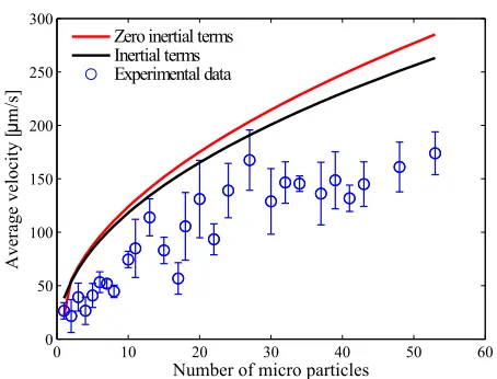
Fig. 4. Average velocity of the cluster of micro particles versus the number of micro particles within the cluster. The average velocity is calculated from 5 motion control experiments. At these motion control experiments, electromagnet A is activated with a current of 0.5 A (darker shade in the inset). The average velocity increases linearly with the number of micro particles up to ∼20 micro particles. The average velocity saturates at 140µm/s. This allows us to use ∼20 micro particles per cluster in the rest of our experimental work. The letter A, B, C and D represent the electromagnets (Fig. 1). Paramagnetic micro particles with average diameter of 100µm are used in this experiment (PLAParticles-M-redF-plain from Micromod Partikeltechnologie GmbH, Rostock-Warnemuende, Germany).
Since we control the current through each of the electro-magnets rather than the magnetic fields, it is convenient to represent the magnetic force as a function of the currents. Substituting (22) in (5) yields
F(P) =αp
4 3πr
3 p∇ I
T
e
BT(P)Be(P)I
, (24)
where I ∈ R4×m is the current vector. The magnetic
force can be controlled by controlling the currents at each electromagnet. We rewrite (22) into (25) to calculate the desired currents for a given magnetic force or field
ie=Bee(P)†Be(P), (25)
whereBee(P)†is the pseudo-inverse ofBe(P). The magnetic
force on the cluster of micro particles depends on the number of micro particles within the cluster (6). Therefore it is important to select the number of micro particles within the cluster.
C. Optimal Cluster Size
In order to develop a control system for the motion of a cluster of micro particles, first the optimal cluster size has to be chosen. This is done by evaluating the velocity of the cluster at different cluster sizes under a constant magnetic field. The result of this experiment is shown in Fig. 4. In this experiment, a current of 0.5 A is applied on electromagnet A. This current generates a gradient of the magnetic field squared of 0.2 T2/m. Five experiments are conducted for
each cluster size. Fig. 4 shows an almost linear increase of the average velocity of the clusters up to∼20 micro particles. This implies that (6) is a valid assumption. Substituting (24)
0 10 20 30 40 50 60
0 50 100 150 200 250 300
Number of micro particles
A ve ra ge ve loc it y [ µ m /s ]
[image:7.612.60.277.52.226.2]Zero inertial terms Inertial terms Experimental data
Fig. 5. Comparison between experimental and modeled velocities of the cluster of micro particles in the absence and presence of the inertial term. The magnetic force of the modeled values is based on a magnetic field computed by a finite element model of our magnetic system. In this comparison, (26) is used to compute the magnetic force. The drag force is calculated using (14) assuming that the cluster has a circular geometry. This comparison shows negligible difference when we include the inertial term. Further, we observe a big deviation in the modeled values for cluster sizes larger than 30 micro particles.
in (6) yields the following magnetic force on a cluster of micro particles
Fc(P) =
n X i=1 αp 4 3πr 3 pi∇ I
T
e
BT(P)Be(P)I
, (26)
where rpi is the radius of the ith particle in the cluster.
We observe a saturation in the velocity for a cluster size of∼20 micro particles and at average velocity of 140µm/s. Therefore, a cluster size of ∼20 micro particles is chosen to be the optimal cluster size throughout our experimental work. A larger cluster size would not provide larger net force. However a larger cluster size has more limitations due its size relative to the size of the workspace of 2.4×1.8 mm2. The asymptotic behavior can be due to the increase of Reynolds number. At higher Reynolds numbers the drag force increases quadratically with the velocity, not linearly. Also the size of the workspace is a reason for the asymptotic behavior of the cluster. Larger cluster sizes reach closer to the edge of the reservoir during motion control experiments, and therefore experience larger meniscus forces.
D. Model Validation and Shape Analysis
[image:7.612.320.547.59.232.2]Fig. 6. Demonstration of the dynamic nature of the shape of the cluster of micro particles. The shape of the cluster varies with time and at each experiment. This demonstration shows 5 different shapes for the same cluster of 20 micro particles. The difference in shape explains the deviation in contour and velocity. From left to right, the cluster respectively has a contour length (l) of 3227µm, 2595µm, 2531µm, 2419µm and 2404µm and an average velocity (v) of 88µm/s, 141µm/s, 100µm/s, 175µm/s and 150µm/s.
0 10 20 30 40 50 60 0 1000 2000 3000 4000 5000 6000
Number of micro particles
Cl us te r c ont our [ µ m ] k=10 k=8 k=6 k=4 k=2
Ellipso id approximation Circlular approximation
[image:8.612.61.553.53.130.2]Experimental data
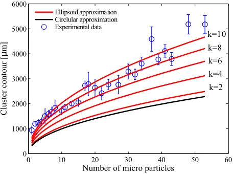
Fig. 7. Comparison between experimental and modeled contours versus the number of micro particles in a cluster. Modeled values are computed by approximating the geometry of the cluster with a circle and ellipsoid with a ratio of 2, 4, 6, 8 and 10. Based on the result of this comparison, an ellipsoid with a ratio of 8 is selected to be the optimum estimation for the geometry of a cluster of micro particles
range. At cluster sizes larger than 30 micro particles, the model values show larger deviations. This can be due to the reasons explained in Sec. II-C but also due to the geometry of the cluster. In order to investigate if a circular disc is the best assumption for the geometry of a cluster of micro particles, we analyze the shape of all the clusters used for the experiment of Sec. II-C. We calculate the contours of these clusters and compare these contours with the contours of a circle and ellipsoid with different ratios between the major and minor axis, k=a:b. The process of calculating the contour of a cluster of micro particles is shown in Fig. 11. First the original image (Fig. 11.a) is loaded into MATLAB and then it is converted to a binary image (Fig. 11.b) which makes it possible to compute the perimeter line (Fig. 11.c). The contour of the cluster in units of pixels is obtained by taking the area of the perimeter line since these lines are 1 pixel in width. The images consist of 512×384 pixels which cover a workspace of 2.4 mm×1.8 mm which means 4.6875µm per pixel. The contours of the ellipsoids are estimated using
Ce=π[3(a+b)−
p
(a+ 3b)(3a+b)], (27)
0 10 20 30 40 50 60
0 50 100 150 200 250 300
Number of micro particles
V el oc it y [ µ m /s ]
[image:8.612.320.546.202.374.2]Ellipsoid approximation k=8 Circlular approximation Experimental data
Fig. 8. Comparison between modeled and experimental velocities of the cluster of micro particles. The modeled values are computed by approximating the geometry of the cluster with a circle and an ellipsoid with a ratio between the major and minor axis of 8. For the ellipsoid (28) is used as the equation for drag force. Based on this comparison, we conclude that an ellipsoid with a ratio of 8 is the best approximation to model a cluster of micro particles within our magnetic system
where a and b are the major and minor axis lengths of the ellipsoid. Fig. 7 shows the modeled ellipsoid contours, a contour of a circular disc and the contours of the clusters of micro particles with the number of micro particles in a cluster. Based on Fig. 7, we select an ellipsoid with ratio of k=8, to represent the geometry of a cluster of micro particles. The deviations in cluster contour of the experimental values are due to the varying geometrie of a cluster. Fig. 6 shows an example of the different geometries and contours a cluster of 20 micro particles can have.
The viscous drag coefficient of a randomly moving ellip-soid is given by [16]
ze=
6πηa ln (2a
b )
, (28)
which yields a drag force:
Fde(P˙) =
6πηa
ln (2ba) ˙
P. (29)
This equation is only valid for a2>> b2. Fig 8 shows the
[image:8.612.59.287.204.374.2]0 10 20 30 40 50 60 0 20 40 60 80 100 120 140 160 180 200
Number of micro particles
V el oc it y[ µ m /s ]
Zero inertial terms Inertial terms Experimental data
Fig. 9. Experimental and modeled velocities of the cluster of micro particles in absence and presence of the inertial term. The modeled velocities are computed by approximating the geometry of the cluster to be an ellipsoid with a ratio between the major and minor axis of 8. The result of this comparison allows us to neglect the inertial term in the equation of motion.
is a better representation of a cluster of micro particles in our magnetic system than a circle. Therefore, we use (29) to model the drag force in our magnetic system.
Our estimation for the Reynolds number of a cluster of micro particles (21) is based on a circular geometry. Therefore we made a comparison between including and excluding the inertial term for an ellipsoid-shaped cluster of micro particles. Fig. 9 shows our model with and without the inertial term. Based on Fig. 9, we conclude that the inertial term can be neglected.
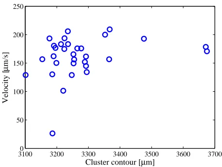
[image:9.612.320.549.61.233.2]A cluster of micro particles never occurs with equal geometry (hence the contour deviations in Fig. 7). Fig. 6 shows an example of the different shapes of a cluster of 20 micro particles. In order to investigate if there is a relation between the shape of a cluster of micro particles and its drag force, 30 velocity experiments with a cluster of 20 micro particles are done. In these experiments the cluster of micro particles moves from the middle of the workspace to the edge under a gradient of the magnetic field squared of 0.2 T2/m.
Fig. 10 shows a comparison of the different contours and velocities of these experiments. From these experiments, we conclude that there is no clear relation between the contour of a cluster of micro particles and its drag force.
E. Closed-Loop Control
We conclude from Fig. 9 that the inertial force can be neglected, and therefore the following equation of motion for a cluster of micro particles holds:
F(P)−Fde(P˙) = 0. (30)
In order to allow the cluster to follow any reference position (Pref) within the workspace of the magnetic system, the
following magnetic force is devised:
F(P) =Fde(P˙)−Mn(Kd˙e+Kpe), (31)
31000 3200 3300 3400 3500 3600 3700 50
100 150 200 250
Cluster contour [µm]
Velocity [
µ
m/s]
Fig. 10. Relation between the contour and the velocity of a cluster of micro particles. These results are based on 30 velocity experiments with a cluster of 20 micro particles. During these experiments the cluster of micro particles is pulled from the middle to the edge of the workspace under influence of a gradient of the magnetic field squared of 0.2 T2/m. We conclude from this figure that there is no clear relation between the contour of a cluster and the velocity of the cluster.
whereMn is the nominal mass of the cluster and Kp and Kdare the controller positive-definite gain matrices, and are
given by
Kp= "
kp1 0
0 kp2
#
andKd= "
kd1 0
0 kd2
#
, (32)
wherekpi and kdi, for (i= 1,2), are the proportional and
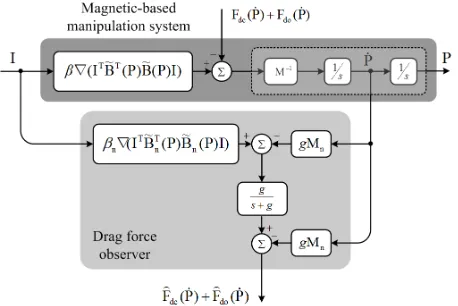
derivative gains, respectively. The drag force in (31) only models the drag of the cluster of micro particles. An extra drag force term has to be included, when performing motion control of a micro-object. The total drag force is estimated by a drag force observer (Fig. 12). From this drag force observer we estimate a drag force:
b
Fd(P˙),Fbdc(P˙) +Fbdo(P˙), (33)
whereFbdc(P˙) andFbdo(P˙)are the observed drag force on
the cluster and on a micro object, respectively. Using the drag force observer, the following magnetic force is computed:
F(P) =Fbd(P˙)−Mn(Kd˙e+Kpe). (34)
The estimated drag forceFbd(P˙)is calculated using the drag
force observer (Fig. 12) [17]:
b Fd(P) =
g s+g
h
F(P)−gMnP˙
i
−gMnP˙, (35)
whereg is a positive gain of the low-pass filter of the drag force observer (Fig.12). The position (e) and velocity (˙e)
tracking errors of the cluster are given by
[image:9.612.63.286.62.232.2](a) (b) (c)
[image:10.612.321.550.241.407.2]Fig. 11. Computation of the contour of a cluster of micro particles using image processing. (a) The original image. (b) The binary image. (c) Perimeter line obtained from the binary image. In order to calculate the contour of a cluster of micro particles, the original image first is converted to a binary image and then processed to a perimeter line. The perimeter line is 1 pixel in width. Therefore, the contour of the cluster can be calculated by taking the area of the perimeter line.
Fig. 12. Drag force observer [17]: The drag forces on the cluster of micro particles(Fbdc(P˙))and the micro-object(Fbdo(P˙))are estimated using the applied current(I)to each of the electromagnets, and the velocity(P˙)of the cluster. The estimated drag forces(Fbdc(P˙)andFbdo(P˙))are used by the control law (34) to compensate for the drag forces.MandMnare the mass of the cluster and its nominal value, respectively. gis the positive gain of the low-pass filter associated with the drag force observer.βis a magnetic constant given byαp43πr3p, andβnrepresents its nominal value.
wherePref andP˙ref are the reference position and velocity,
respectively. Substitution of the desired magnetic force (31) in (30) yields the following tracking error dynamics:
Kd˙e+Kpe= 0. (37)
This means that the tracking error (e) is stable if and only if Kd−1Kp > 0. Therefore, the desired magnetic force
allows the cluster to follow the given reference position, while simultaneously compensating for the drag forces on the cluster and the micro-object.
III. EXPERIMENTAL SETUP
All experiments are conducted on a magnetic system consisting of a fluid reservoir, 4 electromagnets and a mi-croscope with camera to provide feedback for the control system. Micro-objects and micro targetstructures to perform micro assembly are made of SU-8-50 and SU-8-100.
Fig. 13. Fabrication of the micro-objects: (a) Spin coating of SU-8 (MicroChem Corp., Newton, USA) on a silicon wafer. (b) Transferring the patterns of the micro-objects to the SU-8 layer after pre-bake and ultraviolet-exposure. (c) Realization of the micro-objects after post-exposure bake and developing the unexposed SU-8 layer. (d) Release of the micro-objects by etching the silicon wafer.
A. Magnetic System
The magnetic system (Fig. 3) consists of four or-thogonal electromagnets surrounding a fluid reservoir of 11.5 mm × 11.5 mm. The magnetic system is capable of generating a magnetic field and gradient of the magnetic field squared of 5 mT and 0.4 T2/m, respectively. A microscopic vision system mounted on top of the electromagnets tracks the motion of the cluster of micro particles. The tracking information is used to realize the control system. Paramag-netic micro particles with average diameter of 100 µm are used (PLAParticles-M-redF-plain from Micromod Partikel-technologie GmbH, Rostock-Warnemuende, Germany).
B. Micro-objects and Micro-targetstructure
[image:10.612.63.292.245.398.2]TABLE I
MANUFACTURING PROCESS PARAMETERS FOR THE MICRO-OBJECTS(SU-8-50)AND TARGETSTRUCTURE(SU-8-100)
Type Thickness Spin Pre-bake Expose Post-exposure bake Develop Hard bake
[µm] Speed Temp. Time Time Temp. Time Time Temp. Time [rpm] [◦C] [min] [s] [◦C] [min] [min] [◦C] [min] SU-8-50
50±8% 3000 95 20 50 80 10 3 120 120
(micro-objects) SU-8-100
100±8% 3500 95 120 24 75 35 5 120 120
(targetstructure)
TABLE II
EXPERIMENTAL MOTION CONTROL RESULTS OF THE CLUSTER OF MICRO PARTICLES. THE RESULTS ARE OBTAINED FROM 10MOTION CONTROL TRIALS
Motion Control Operation
Average Velocity [µm/s]
Maximum Average Velocity [µm/s]
Average Tracking Error [µm]
Maximum Tracking Error [µm]
Execution Time [s]
Point-to-Point Control 193±85 327 37±47 110
-Micro Manipulation 194±63 297 103±81 150
-Micro Assembly 193 - - - 18 s
coated with a layer of SU-8-50 (Fig. 13 (a)). After pre-baking the wafer, patterns of the micro-objects are transferred to the SU-8 layer by ultraviolet (UV) exposure (Fig. 13 (b)). After that, the wafer is further baked (post-exposure bake). The micro-objects are realized by developing the SU-8 layer in RER600 (ARCH Chemicals)(Fig. 13 (c)). To achieve mechanical stability of the micro-objects, the wafer is hard baked. Now an oxygen plasma treatment is performed on the SU-8 micro-objects for 30 seconds to make them hydrophilic. The micro-objects are released by etching away the silicon wafer in a 5 wt%TMAH solution at 85◦C (Fig. 13 (d)). A filter is used to collect the micro-objects.
Fabrication of the micro-targetstructure (Fig. 1) is similar to that of the micro-objects. However, instead of releasing it by etching away the silicon wafer, the silicon wafer is diced into 11 mm2 pieces which all have a micro structure and fit into the fluid reservoir of the magnetic system.
IV. EXPERIMENTAL RESULTS
The cluster of micro particles is steered towards different reference positions within the workspace of our magnetic system. Furthermore, feasibility of employing a cluster of micro particles for micro assembly applications is investi-gated. First, point-to-point motion control experiments with a cluster of micro particles are conducted. Second, micro manipulation experiments are done, the cluster is used to direct a micro-object towards different reference positions throughout the workspace. Third, micro assembly experi-ments are carried out, the cluster is employed to steer the micro-object into a selected destination within a targetstruc-ture. Table II shows the experimental results of the motion control operations. The parameters of this experiments are listed in Table III.
A. Point-to-Point Motion Control
Fig. 14 shows the result of a point-to-point motion con-trol operation of a cluster of micro particles. The average velocity and tracking error of 10 point-to-point motion control experiments are 193±85µm/s and 37±47µm. The maximum average velocity and tracking error are 327µm/s and 110 µm. We observe a large difference of 134 µm/s and 73µm between the average velocity and tracking error and the maximum average velocity and tracking error. Also there are large deviations in the average velocity and the tracking error, 85µm/s and 47 µm, respectively. The large deviations in tracking error can be explained by the different reference positions assigned to the clusters. We observed that some locations in the workspace are harder to reach than others. The large deviations in the average velocity can be explained by the anisotropic nature of our magnetic system. The magnetic field of an electromagnet drops faster in the perpendicular direction from the electromagnet than in the parallel direction. Our magnetic system has four electromagnets, therefore the magnetic field drops faster in the diagonal direction than in the horizontal and vertical direction. This causes higher directional magnetic field gra-dients and therefore faster motion in the diagonal direction compared to the horizontal or vertical direction. We conclude from this experiment that the selected cluster size of ∼20
TABLE III
EXPERIMENTAL PARAMETERS AND CONTROLLER GAINS
Parameter Value Parameter Value rp[µm] 50 n ∼20 Mn[kg] 7.33×10⁻¹⁰ χm 0.17±0.007
η[mPa.s] 1 g[rad/s] 30
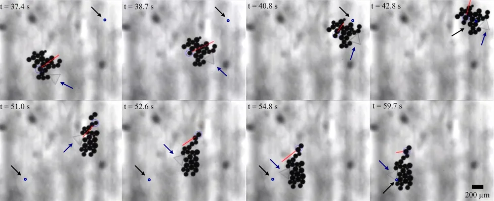
Fig. 14. Motion control of the cluster of micro particles under the influence of the applied magnetic fields at various time(t)instants. The cluster follows two reference positions indicated by the black and blue arrows in the upper and bottom rows, respectively. At this particular experiment the cluster of micro particles follows these reference positions at a velocity of 144µm/s, and maximum position tracking error of 50µm. Average velocities and tracking errors of 10 motion control experiments are listed in Table II. This motion control experiment is done using the control law (34). The controller gains are listed in Table III. The cluster consists of 19 micro particles. Paramagnetic micro particles with average diameter of 100µm are used in this experiment (PLAParticles-M-redF-plain from Micromod Partikeltechnologie GmbH, Rostock-Warnemuende, Germany). The large blue (light) circle is assigned by our feature tracking software [28], whereas the small blue circle indicates the reference position. The red (light) line indicates the velocity vector of the cluster.
micro particles operates in the workspace of our magnetic system and that the magnetic field gradients of the system provide enough magnetic force to overcome the drag force acting on the cluster.
B. Motion Control of Micro-objects
In order to investigate the feasibility of using a cluster of micro particles for micro assembly applications, first micro manipulation experiments with micro-objects are executed. A micro-object is pushed or pulled towards a reference position within the workspace of our magnetic system. Fig. 15 shows an example of a micro manipulation experiment. Based on 10 micro manipulation experiments, the average velocity and tracking error are 194±63 µm/s and 103±81 µm with a maximum average velocity and tracking error of 297 µm/s and 150 µm (also listed in Table II). From the small difference between the average velocity of the point-to-point motion control experiment of a cluster of micro particles and the average velocity of the micro manipulation experiment, we conclude that (29) also holds for the drag force during micro manipulation experiments. We observe a big tracking error of the micro manipulation experiment. This is because not the micro-object but a micro particle in the cluster is tracked and therefore this micro particle is steered toward the reference position, dragging the micro-object with it. This experiment shows that the cluster of micro particles generates enough force to push or pull a micro-object towards a given reference position.
C. Micro Assembly Application
Finally, the cluster of micro particles is employed to perform a micro assembly task. A micro-object is assembled within a targetstructure. Fig.16 shows a micro assembly operation. A triangular micro object is steered towards a specific destination within the targetstructure. First a cluster
of micro particles is used to pull the triangular micro-object out of a rectangular destination within the targetstructure. The cluster is then used to push the triangular micro-object into its triangular destination within the targetstructure. After completing its micro assembly task, the cluster moves away from the micro-object. The total micro assembly task is exe-cuted with an average velocity of 193µm/s and an execution time of 18 s. From this experiment we can conclude that micro assembly using a cluster of micro particles is feasible.
V. DISCUSSION
Interaction forces at micro scale limited us to accurately control the cluster of micro particles in the neighbourhood of the target structure. Interaction phenomena at micro scale are a common topic of interest in research to micro manipulation systems [18]. In order to improve micro assembly results in the future, further investigation of interaction forces at micro scale has to be carried out. Also, to get more succesful micro assembly results, adjustments to the targetstructure could be made. A target structure incorporated in the fluid reservoir could solve the problem. Furthermore, we encountered large deviations in postion tracking error and velocity. This is due to the anisotropic nature of our magnetic system. Different directional magnetic field gradients cause different maximum forces for different directions.
Fig. 15. Micromanipulation of a triangular micro-object towards reference positions using a cluster of micro particles at various time(t)instants. The cluster pushes the micro-object under the influence of the controlled magnetic fields generated by the control law (34). During this micro manipulation experiment, the velocity of the cluster is 204µm/s, and the maximum position tracking error of 75µm is accomplished (error between the reference position and the center of mass of the micro-object). Average velocities and tracking errors of 10 motion control experiments are listed in Table II. The controller gains are listed in Table III. The large blue (light) circle is assigned by our feature tracking software [28], whereas the small blue circle indicates the reference position. The red (light) line indicates the velocity vector of the cluster of micro particles. The black arrows indicate the first and second reference positions in the top and bottom rows, respectively. The blue arrows indicate the micro-object. The cluster consists of 23 micro particles. Paramagnetic micro particles with average diameter of 100µm are used in this experiment (PLAParticles-M-redF-plain from Micromod Partikeltechnologie GmbH, Rostock-Warnemuende, Germany).
of 37±47µ/s. In order to investigate the utilization of a cluster of micro particles in motion control of micro-objects, micro manipulation experiments are conducted at an average velocity and position tracking error of 194±63µm/s and 103±81µm, respectively. Finally, feasibility of employing a cluster of micro particles to perform a micro assembly task is demonstrated. A micro-object is assembled to a selected destination within a target structure at an execution time of 18 s.
Future work includes control of the cluster of micro particles in the three dimensional (3D) space. Further, au-tomation of the micro assembly task will be achieved. In order to realize this automated micro assembly operation the following steps need to be done:
1) Measurement of the error along the x- and y-axis between the cluster of micro particles and the micro-object, and the micro-object and the target structure 2) Calculation of the angle between the micro-object and
the target structure.
Reduction to zero of the above errors should lead to an automated micro assembly operation. Automation of 3D micro assembly would give an extra error for each of the aforementioned tasks. In addition, auto-focussing needs to be incorporated to the magnetic system for the control in 3D space.
REFERENCES
[1] H. Van Brusse, J. Peirs, D. Reynaerts, A. Delchambre, G. Rein-hart, N. Roth, M. Weck, E. Zussman, “Assembly of Microsystems,” CIRP Annals - Manufacturing Technology, vol. 49, no. 2, pp. 451-472, 2000.
[2] S. Martel, C. C. Tremblay, S. Ngakeng, and G. Langlois, “Controlled manipulation and actuation of micro-objects with magnetotactic bac-teria,”Applied Physics Letters, vol. 89, no. 23, pp. 1-3, 2006. [3] S. Floyd, C. Pawashe, and M. Sitti, “Two-dimensional contact and
noncontact micromanipulation in liquid using an untethered mobile magnetic microrobot,”IEEE Transactions on Robotics, vol. 25, no. 6, pp. 1332-1342, December 2009.
[4] C. Pawashe, S. Floyd, E. Diller, and M. Sitti, “Two-dimensional autonomous microparticle manipulation strategies for magnetic mi-crorobots in fluidic environments,”IEEE Transactions on Robotics, vol. 28, no. 2, pp. 467-477, April 2012.
[5] P. Valdastri, E. Sinibaldi, S. Caccavaro, G. Tortora, A. Menciassi, and P. Dario, “A Novel Magnetic Actuation System for Miniature Swimming Robots,”IEEE Transactions on Robotics, vol. 27, no. 4, pp. 769-779, August 2011.
[6] D. H. Kim, P. S. S. Kim, A. A. Julius, and M. J. Kim, “Three-dimensional control of engineered motile cellular microrobots,” in Proceedings of the IEEE International Conference on Robotics and Automation (ICRA), pp. 721-726, Minnesota, USA, May 2012. [7] M. P. Kummer, J. J. Abbott, B. E. Kartochvil, R. Borer, A. Sengul,
and B. J. Nelson, “OctoMag: an electromagnetic system for 5-DOF wireless micromanipulation,”IEEE Transactions on Robotics, vol. 26, no. 6, pp. 1006-1017, December 2010.
[8] S. Martel, O. Felfoul, J.-B. Mathieu, A. Chanu, S. Tamaz, M. Mo-hammadi, M. Mankiewicz, and N. Tabatabaei , “MRI-based medical nanorobotic platform for the control of magnetic nanoparticles and flagellated bacteria for target interventions in human capillaries,”The International Journal of Robotics Research, vol. 28, no. 9, pp. 1169-1182, September 2009.
[9] S. Martel and M. Mohammadi, “Towards mass-scale micro-asssembly systems using magnetotactic bacteria,” International Manufacturing Science and Engineering Conference (ASME), vol. 2, no. 6, pp. 487-492, Oregon, USA, June 2011.
[10] S. Martel and M. Mohammadi, “Using a swarm of self-propelled natural microrobots in the form of flagellated bacteria to perform com-plex micro-assembly tasks,” inProceedings of The IEEE International Conference on Robotics and Automation, pp. 500-505, Alaska, USA, May 2010.
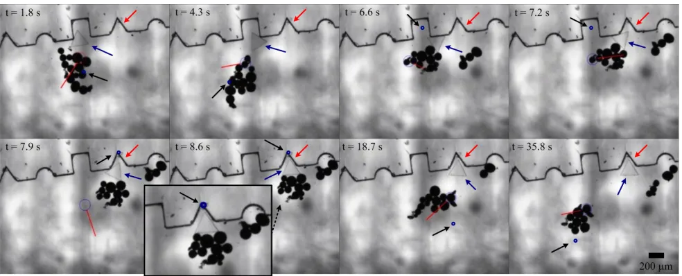
Fig. 16. Microassembly of a triangular microobject to a micro-structure using a cluster of micro particles at various time(t)instants. The cluster selectively steers the micro-object towards the triangular destination within the micro-object. The cluster pulls and pushes the micro-object under the influence of the magnetic fields generated by the control law (34). The execution time of this micro assembly operation is 18 s. During this micro assembly experiment, the average velocity of the cluster is 204µm/s, and the maximum position tracking error is 50µm. The controller gains are:kp1=kp2= 10s−2,
kd1=kd2= 20s−1 andg = 30rad/s. The large blue (light) circle is assigned by our feature tracking software [28], whereas the small blue circle indicates the reference position. The red line indicates the velocity vector of the cluster of micro particles. The black arrows indicate the triangular destination within the micro-structure, whereas the blue arrows indicate the micro-object. The micro-object has an edge length of 190µm. Paramagnetic micro particles with average diameter of 100 µm are used in this experiment (PLAParticles-M-redF-plain from Micromod Partikeltechnologie GmbH, Rostock-Warnemuende, Germany).
[12] S. Fatikow, “Microrobot-Based Assembly of Microsystems, ”NEXUS Research News, vol. 1, pp. 12-14, 1998.
[13] B. J. Nelson, I. K. Kaliakatsos, and J. J. Abbott, “Microrobots for minimally invasive medicine,” The Annual Review of Biomedical Engineering, vol. 12, pp. 55-85, April 2010.
[14] T. H. Boyer,“ The force on a magnetic dipole,”American Journal of Physics,vol. 56, no. 8, pp. 688,August 1988
[15] I. S. M. Khalil, J. D. Keuning, L. Abelmann, and S. Misra, “Wireless magnetic-based control of paramagnetic microparticles,” in Proceed-ings of the IEEE RAS/EMBS International Conference on Biomedical Robotics and Biomechatronics (BioRob), pp. 460-466, Rome, Italy, June 2012.
[16] H. C. Berg, Random Walks in Biology, Princeton University Press,1933.
[17] I. S. M. Khalil, R. M. P. Metz, L. Abelmann, and S. Misra, “Interaction force estimation during manipulation of microparticles,” in Proceed-ings of the IEEE International Conference of Robotics and Systems (IROS), Vilamoura, Portugal, pp. 950-956, October 2012
[18] M. Savia and H.N.Koivo, “Contact Micromanipulation-Survey of Strategies, ”IEEE/ASME Transactions on Mechatronics, vol. 14, no. 4, pp. 504-514, August 2009.
[19] M. S. Sakar, E. B. Steager, D. H. Kim, A. A. Julius, M. Kim, V. Ku-mar and G. J. Pappas, “Modeling, control and experimental charac-terization of microbiorobots,”The International Journal of Robotics Research, vol. 30, no. 6, pp. 647-658, May 2011.
[20] Z. Lu and S. Martel, “Controlled bio-carriers based on magnetotactic bacteria,” in Proceedings of The IEEE International Conference on Solid-State Sensors, Actuators and Microsystems, pp. 683-686, Lyon, France, June 2007.
[21] Z. Lu and S. Martel, ”Preliminary investigation of bio-carriers using magnetotactic bacteria,” in Proceedings of The IEEE Engineering in Medicine and Biology Society Annual International Conference (EMBS), pp. 683-686, New York City, USA, September 2006. [22] S. S. Shevkoplyas, A. C. Siegel, R. M. Westervelt, M. G. Prentiss, and
G. M. Whitesides, “The force acting on a superparamagnetic bead due to an applied magnetic field,”Lab on a Chip, vol. 7, no. 10, pp. 1294-1302, July 2007.
[23] S. Komada, N. Machii, and T. Hori, “Control of redundant manipu-lators considering order of disturbance observer,”IEEE Transactions on Industrial Electronics, vol. 47, no. 2, pp. 413-420, April 2000. [24] S. Katsura, Y. Matsumoto, and K. Ohnishi, “Modeling of force
sensing and validation of disturbance observer for force control,” IEEE Transactions on Industrial Electronics, vol. 54, no. 1, pp. 530-538, February 2007.
[25] B. E. Kratochvil, M. P. Kummer, S. Erni, R. Borer, D. R. Frutiger, S. Schurle, and B. J. Nelson, “MiniMag: a hemispherical electro-magnetic system for 5-DOF wireless micromanipulation,” in Proceed-ings of the 12th International Symposium on Experimental Robotics-Springer Tracts in Advanced Robotics, New Delhi, India, Decem-ber 2010.
[26] R. G. McNeil, R. C. Ritter, B. Wang, M. A. Lawson, G. T. Gillies, K. G. Wika, E. G. Quate, M. A. Howard, and M. S. Grady, “Char-acteristics of an improved magnetic-implant guidance system,”IEEE Transactions on Biomedical Engineering, vol. 42, no. 8, pp. 802-808, August 1995.
[27] I. S. M. Khalil, M. P. Pichel, L. Zondervan, L. Abelmann, and S. Misra, “Characterization and control of biological microrobots,” in Pro-ceedings of the 13th International Symposium on Experimental Robotics-Springer Tracts in Advanced Robotics, Quebec City, Canada, June 2012.
MODELING AND MAGNETIC-BASED MOTION CONTROL
OF A CLUSTER OF MICROPARTICLES
Control of single micro particles
To provide greater magnetic force: a cluster is used
30/1/13 2
INTRODUCTION
CONTROL OF MICRO PARTICLES
Open heart surgery vs. MIS
Picture courtesy: Anova Heart and
Vascular Institute
Minimally invasive surgery (MIS)
30/1/13 3
INTRODUCTION
APPLICATIONS
Introduction
Modeling and control Results Conclusions Future work
Micro assembly for Micro Electromechanical Systems (MEMS)
30/1/13 4
INTRODUCTION
APPLICATIONS
Introduction
Modeling and control Results Conclusions Future work
Wireless magnetic-based manipulation
Wireless micro assembly
30/1/13 5
INTRODUCTION
RELATED WORK
Octomag (M.P. Kummer
et al.,
2010
)
Introduction
Modeling and control Results Conclusions Future work
Optimal cluster size
Closed loop control
Micro manipulation
Micro assembly application
30/1/13 6
INTRODUCTION
APPROACH
30/1/13 7
MODELING AND CONTROL
MAGNETIC SYSTEM
30/1/13 8
MODELING AND CONTROL
MODELING
Introduction
Modeling and control
Results Conclusions Future work
: Mass of the cluster
: Magnetic force
: Drag force on micro-object
: Drag force on the cluster
30/1/13 9
MODELING AND CONTROL
EQUATION OF MOTION
: Mass of the cluster
: Magnetic force
: Drag force on micro-object
: Drag force on the cluster
30/1/13 10
MODELING AND CONTROL
MAGNETIC FORCE MODELING
:
Magnetic dipole moment
:
Magnetic field
:
Permeability coefficient
:
Magnetic susceptibility
:
Micro particle radius
:
Magnetic field map
:
Current through the e
th
electromagnet
Magnetic field:
Magnetic force:
:
current vector
Introduction
Modeling and control
Results Conclusions Future work
(1)
(2)
(3)
(4)
30/1/13 11
MODELING AND CONTROL
DRAG FORCE MODELING AND REYNOLDS NUMBER
Drag force cluster: (Disc)
Drag force micro particle:
: Drag shape factor micro particle
: Drag shape factor cluster
: Fluid dynamic viscosity
Reynolds number micro particle:
Reynolds number cluster:
: Reynolds shape factor micro particle
: Reynolds shape factor cluster
: Fluid density
30/1/13 12
MODELING AND CONTROL
OPTIMAL CLUSTERSIZE
n=1
n=13
n=24
n=48
Assymptote at ~140 µm/s and 20 micro particles
30/1/13 13
MODELING AND CONTROL
EQUATION OF MOTION
Velocity range of 200 µm/s to 500 µm/s
Particles 70% to 100% submerged
30/1/13 14
MODELING AND CONTROL
MODEL VERIFICATION
Introduction
Modeling and control
Results Conclusions Future work
30/1/13 15
MODELING AND CONTROL
SHAPE ANALYSIS
Introduction
Modeling and control
Results Conclusions Future work
K = ratio a/b
30/1/13 16
MODELING AND CONTROL
SHAPE ANALYSIS
Introduction
Modeling and control
Results Conclusions Future work
Ellipsoid ratio k = 8
30/1/13 17
MODELING AND CONTROL
CONTROL
Introduction
Modeling and control
Results Conclusions Future work
30/1/13 18
RESULTS
POINT-TO-POINT CONTROL OF A CLUSTER OF MICRO PARTICLES
Maximum average velocity of
327 µm/s
Maximum average tracking error
of 110 µm
30/1/13 19
RESULTS
MICRO OBJECTS AND TARGETSTRUCTURE
30/1/13 20
RESULTS
POINT-TO-POINT CONTROL OF A MICRO-OBJECT
Maximum average velocity of
297 µm/s
Maximum average tracking error
of 150 µm
30/1/13 21
RESULTS
MICRO ASSEMBLY APPLICATION
Proof of concept
Average velocity of 194 µm/s
Execution time of 18 s
Feasible but still a lot to learn
about interaction forces
30/1/13 22
CONCLUSIONS
Introduction Modeling and control Results
Conclusions
Future work
Optimal cluster size of ~20
microparticles
Point-to-point control: maximum average
velocity 327 µm/s and maximum average
tracking error of 110 µm
Micro manipulation: maximum average
velocity 297 µm/s and maximum average
tracking error of 150 µm
Micro assembly with an average velocity
Investigation of interaction forces at micro scale
Control and micro assembly in 3D space
Automated micro assembly
Nano scale
30/1/13 23
FUTURE WORK
I. S. M. Khalil, F. van den Brink, O. S. Sukas, L. Abelmann, and S. Misra,
“Microassembly using a cluster of paramagnetic microparticles,”
in
Proceedings of The IEEE International Conference on
Robotics and Automation (ICRA),
Karlsruhe, Germany, May 2013. In Press
30/1/13 24
Questions?
30/1/13 25