Application of coupled electro-thermal and physics-of-failure-based analysis to the design of accelerated life tests for power modules
1Mahera Musallam , 2Chunyan Yin, 3Chris Bailey, 4C. Mark Johnson 1, 4 University of Nottingham/School of Electrical and Electronic Engineering,
Nottingham, United Kingdom.
Tel.: +44 (0) 115846 6890, Fax: +44 (0) 115951 5616
2, 3 School of Computing and Mathematical Sciences, University of Greenwich, UK
Email: [email protected], [email protected], [email protected], [email protected]
ABSTRACT
In the reliability theme a central activity is to investigate, characterize and understand the contributory
wear-out and overstress mechanisms to meet through-life reliability targets. For power modules, it is
critical to understand the response of typical wear-out mechanisms, for example wire-bond lifting
and solder degradation, to in-service environmental and load-induced thermal cycling. This paper
presents the use of a reduced-order thermal model coupled with physics-of-failure-based life models
to quantify the wear-out rates and life consumption for the dominant failure mechanisms under
prospective in-service and qualification test conditions. When applied in the design of accelerated life
and qualification tests it can be used to design tests that separate the failure mechanisms (e.g.
wire-bond and substrate-solder) and provide predictions of conditions that yield a minimum elapsed test
time. The combined approach provides a useful tool for reliability assessment and estimation of
remaining useful life which can be used at the design stage or in-service. An example case study
shows that it is possible to determine the actual power cycling frequency for which failure occurs in
the shortest elapsed time. The results demonstrate that bond-wire degradation is the dominant failure
mechanism for all power cycling conditions whereas substrate-solder failure dominates for externally
applied (ambient or passive) thermal cycling.
KEYWORDS: Reliability, Real-time, Electro-thermal models, Power cycling, Half-bridge IGBT,
I. INTRODUCTION
Power electronics is the only technology that can deliver efficient and flexible conversion and
conditioning of electrical energy and thus underpins much of the technology supporting the
low-carbon economy. As a consequence it is becoming increasingly important in a wide range of transport
and energy applications including smart grids, aerospace, electric and hybrid cars, industrial process
control, consumer electronics and lighting.
A fundamental consequence of an increasing reliance on power electronics in energy and transport
applications is an accompanying requirement for equipment to be available when needed with a
minimum risk of failure in service. The proportion of time that a piece of equipment is available for
use, as opposed to being unavailable due to unforeseen failure or unscheduled maintenance, is defined
as the through-life availability. Maximizing through-life availability can be realized either by design,
through exceptional levels of inherent reliability, or through the use of availability enhancing
techniques such as multiply redundant systems and scheduled maintenance. Health management tools
which can accurately predict the remaining life of a power electronic system are highly desirable for
availability critical applications since they can be used to schedule preventative maintenance, thus
reducing operating costs and minimizing disruption to services [1, 2, 3].
In power semiconductor modules, such as IGBT (Integrated Gate Bipolar Transistor) modules, the
dominant wear-out mechanisms are generally driven by thermo-mechanical effects, for example by
thermal cycling or by long-term exposure to extreme temperatures [4, 5, 6, 7]. The heat transfer path
from die to coolant consists of many different materials, each characterized by different physical
properties, in particular different coefficients of thermal expansion and different mechanical stiffness.
Thermal stress is generated at various locations within the power module by thermal deformation
because of the difference of the coefficients of thermal expansion (CTE) of power modules’
Fig.1: The internal structure of a typical IGBT module.
Thermal cycling can cause repetitive stresses which cause fatigue and eventual failure, particularly at
the interfaces between dissimilar materials. Affected features include bond-wires and solder layers.
These failures may occur at different rates for different module designs and applications [8, 9] where
the thermal cycling can be as a result of changing environmental or operational (load) conditions [10,
11]. Fig. 2 and 3 illustrate two common failures observed in power modules.
Fig.2: Wirebond Failure Fig.3: Solder Failure
II. RELIABILITY PREDICTION
The reliability of a power electronics system is its ability to perform as intended for a specified period
of time in its lifecycle environment. Traditional reliability prediction methods for electronic products
include MIL-HDBK-217 [12], Tecordia[13], PRISM[14], and FIDES[15]. These methods rely on a
set of collected failure data and generally assume constant failure rates and use modifiers to account
for various quality, operating and environmental conditions. Furthermore, none of these handbook
prediction methods identify failure modes or mechanisms, nor do they involve any uncertainty
analysis. Hence, they offer limited insight with serious faults into practical reliability issues.
Silicon Die
Copper
Solder Joint Failure Al, α=23.8x10⁻⁶ppmK-1
Si, α=2.6x10⁻⁶ppmK-1 crack
500μm
Thermal Grease
Baseplate
Heatsink
Substrate Solder Copper
Alumina Copper
A. Prognosis and Health Management Techniques
A practical alternative way of looking at product reliability and life cycles conditions is called
prognosis and health management (PHM) [16]. PHM is the process of monitoring the health of a
product and predicting the remaining useful life of this product by assessing the extent of degradation
of a product from its original state of health and its expected usage conditions [17, 18,19].
Being able to predict the degradation of a power electronic module in its working environment will
greatly aid in providing advance warning of failures; minimizing unscheduled maintenance,
extending maintenance cycles, reducing the life cycle cost of equipment by decreasing inspection
costs and spare parts inventory [20, 21, 22].
A number of approaches in the literature [23, 24, 25] have been used for prognosis of health
management of power devices which include data driven techniques and physics-of-failure
techniques [26, 27, 28, 29]. In data driven techniques the current and historic information is used to
statistically and probabilistically derive estimates of the remaining useful life for the product [30, 31,
32]. To use data driven techniques, a suitable precursor needs to be identified depending on the
application, i.e. voltage, temperature or current. Once such precursors are identified, they are
monitored continually during the (application) usage. If there is a change in the current observations
compared to the previous trend observed from the healthy product, it signifies that degradation is
taking place. This technique assumes that there is a measurable effect that can be monitored during
operation, for example a change in voltage, current or temperature compared to the expected profile
[33]. Precursor techniques have been successfully applied to monitor the degradation of selected
thermal interfaces e.g. base-plate to heatsink [34], where both heat-sink and base-plate temperatures
can be easily measured. Unfortunately, degradation in bond wires and solder layers are difficult to
detect from simple external measurements of parameters such as forward voltage or module
rather than progressive. Although the sensitivity of data driven methods can be increased through
additional sensors and measurement hardware, this will increase costs and possibly reduce the overall
reliability of the system.
B. Physics-of-Failure (PoF) models
The importance of investigating PHM techniques is to deliver models that can provide an accurate
life consumption to predict expected life under a range of prospective mission profiles. The same
models, when driven by the actual in-service conditions, can be employed as part of a real-time health
management system to provide advance warning of failure (prognostic function) and thus guide
preventative maintenance.
Differing from the traditional handbook methods, physics of-failure (PoF) based reliability analysis
emphasizes the understanding of the physical processes and mechanism of failures. This science
based approach using both computer modeling and experimental techniques, can potentially provide
more accurate reliability predictions than the traditional handbook methods [35, 36, 37].
The Physics-of-Failure (PoF) approach utilizes knowledge of the life-cycle load profile package,
architecture and material properties to identify potential failure mechanisms. PoF based reliability
analysis and prediction methods played an increasingly important role in the power electronics
modules design and failure analysis. These approaches use physics-based models to predict stress,
damage and reliability [38, 39]. By combining computer modeling and failure mode/mechanism
analysis methods, failures can be predicted before they occur by modelling the failure mechanism
(crack propagation). A number of preliminary models have been developed for IGBT modules [40,
41,42]. For example a typical method to estimate time-to-fail of solder interconnects makes use of
the Coffin-Manson model [43, 44,45]:
b p f
L N
)
(
where L is the solder interconnect length, p the damage indicator, Nf is the number of cycles to
fail, α and b are constants derived from the material’s characteristics. Based on the accumulated
plastic strain represented by the damage indicator, the number of temperature cycles to fail can be
calculated and hence giving an indication of the life consumption of the power module.
C. Life-time Models for Wire-bonds and Substrate-solders
To establish a PoF model for bond-wire wear-out, thermal fatigue tests of the aluminum bonding
wires were studied over a range of temperature variation ΔT between 50°C and 180°C and the number
of cycles to fail was observed at each ΔT. From these results an empirical lifetime model for wire
lift-off can be derived and expressed as a function of the cyclic temperature ΔT, for example as described
in [38]:
597 . 3 11) 10 * 4 . 1
(
T
Nf
(2)
where Nf is the number of cycles to failure, here defined as the point at which wire lift-off occurs,
and ΔT is temperature variation. It is inconvenient to run the thermal fatigue tests for small
temperature variations (ΔT) due to the long test times required, so this model is strictly only valid for
C T
C
180
50 and for temperatures less than 125°C. However, for the purposes of calculating
life consumption, the model is extrapolated for values of T50C. This is a reasonable assumption
provided the mechanics of the wear-out process remain the same for lower temperature fluctuations.
Fig. 4 represents the life time extraction model for the IGBT bond-wire over a range of temperature
Fig. 4: Life time extraction model for the IGBT bond wire interconnect [38].
In order to study the substrate-solder (solder layer connecting the isolation substrate to the baseplate)
failure mechanism, thermal fatigue tests were performed for the solder-substrate joints and then
investigated by simulating the crack growth process under a set of prescribed field temperature
profiles that cover the period of the operational life [38]. The overall crack length in the solder joint
for all different thermal profiles and number of cycles for each profile is predicted [46].
As fatigue is driven by the temperature profile of the power module, the degree of the damage of the
solder interconnect can be estimated based on the module’s temperature history [47]. Performing
stress and damage accumulation analysis made it possible to combine the damage information from
thermal fatigue experiments [46] with computer modeling using Finite Element Analysis (FEA). FEA
modeling was undertaken at different design points and the damage criteria was defined as the time
it takes for the crack to have an area that equals 20% of the total solder interconnect area.
In order to identify the best fitting function for the accumulated plastic strain Δεp, the least square
fitting technique was used to provide an approximation model which relates the plastic strain (Δεp)
with the two design variables (ΔT, Tm). As a result, a reduced order thermo-mechanical model for
SnAg solder material in IGBT power module was developed as in equation (3).
TTm Tm
T Tm
T
Ln(p)17.730.2984 0.07957 0.001722 2 0.0002478 2 0.0005389
(3) 0.0E+00
5.0E+04 1.0E+05 1.5E+05 2.0E+05
40 60 80 100
Nu
m
b
er
o
f
cy
cles
to
Fail (
Nf
)
Δεp is the damage indicator based on the accumulated plastic strain over one cycle. T is
temperature variation, Tm is the mean temperature.
In order to estimate the reliability of the power module in terms of number of cycles to failure, the
model in (3) was integrated with the Coffin-Manson model in equation (1). Therefore, the number of
cycles to fail Nf (i.e. number of cycles needed for the crack length to reach L), can be calculated as
in equation (4).
023 . 1
) ( 0056 .
0 p
f
L N
(4)
The constants 0.0056 and 1.023 are derived based on the characteristics of the solder material [46].
It should be noted that the model in equation (3) is valid for mean temperatures between 24C and
90C and ΔT between 6C and 90C. It is notable that the mathematical form of equation (3) is
unrealistic for small ΔT since Δεp does not tend to zero as ΔT tends to zero. Thus, regrettably the
model in equation (4) predicts an unrealistic finite life at zero ΔT and is thus not suitable for general
reliability prediction. To avoid this problem, a revised general functional form of the
Coffin-Manson model is used as illustrated in equation (5):
m
m
f AT BT
N exp (5)
where A(Tm) and B(Tm) are the coefficients of equation (5) and they are functions of the mean
temperatures (Tm). For each individual mean temperature (Tm) the accumulated plastic strain Δεp in
equation (3) is calculated over a range of ΔT then Nf (number of cycles to fail) at that particular mean
temperature is obtained using equation (4). Therefore, equation (5) can be expanded to many
individual equations each at different mean temperature. Fig. 5 illustrates the substrate-solder life
time model as individual curve fits for the model of equation (5) as a function of the temperature
variations at different mean temperatures. Each curve represents the number of cycles to fail as a
temperature. As expected, it is clear that both the temperature range and mean temperatures affect the
life time consumption.
Fig. 5: The substrate-solder life time model as a function of the temperature variations at different values of mean temperatures.
III. PREDICTING THE LIFE TIME OF POWER MODULES
This work investigates the impact of both load power cycling and passive (environmental) thermal
cycling on the wire-bond and the substrate-solder wear-out mechanisms. The compact electro-thermal
model described in [48, 49] presented a real-time model for a typical IGBT half bridge module which
was used to estimate the temperatures of significant points within the power modules such as the die
junction temperature, substrate, and base plate temperature. This model uses a fixed frequency Pulse
Width Modulation (PWM) current controller scheme in which the current control loop is updated
synchronously each PWM cycle. With the knowledge of the operational profile (the real-time input
variables such as the phase current), the power dissipated by each active device within the module
was determined giving the on-state and switching losses as a function of the measured device current
and the estimated temperature. This model provided an accurate representation of the module’s
dynamic thermal behavior in the form of an M x N transfer function matrix (equation (6)).
0.0E+00 5.0E+04 1.0E+05 1.5E+05 2.0E+05 2.5E+05
20 40 60 80
Nu
m
b
er
o
f
cy
cles
to
F
ail
(Nf
)
ΔT(ºC)
Tm=20ºC Tm=40ºC
Tm=60ºC Tm=80ºC
Tm=20ºC Nf =7*1012 ΔT-4.3944
Tm=40ºC Nf =1*1012 ΔT-4.0559
Tm=60ºC Nf =2*1011 ΔT-3.7174
Tm=80ºC Nf =3*1010 ΔT-3.3789
A Nin in in MN M M NN N N N N Baseplate Solder Substrate Solder JN J J T P P P a a a a a a a a a a a a T T T T T T T 2 1 2 1 2 1 2 22 21 1 12 11 1 _ 2 _ 2 1 (6)
The matrix terms a11….aMN represent the transfer function of each heat transfer path, TA is the ambient
temperature, P1in…PNin are the heat sources and TJ1….TJN…TBaseplate are the temperatures at certain
points within the module such as the device junctions, solder, substrate and baseplate. This model is
used to provide continuous real-time estimates of temperatures within the module in response to any
operational profile.
In this work real-time junction and substrate-solder temperatures were obtained using the previously
mentioned compact model which was operating in real-time using a DSpace system [50]. The load
profile is applied to a full-bridge IGBT converter as shown in Fig.6.
Fig. 6: A schematic diagram of the IGBT converter under test.
For the purpose of this work, the full bridge IGBT converter consisted of two (300A, 1200V) IGBT
temperature at 40ºC. The converter was connected to the current controller which is operated by the
PWM fixed frequency system in real-time and monitored via the DSpace system.
Having obtained temperature estimates for the significant features in the power module such as the
die junction temperature, substrate, and base plate temperature, a cycle counting algorithm can be
applied offline to automatically calculate the number of cycles the temperature-time data encountered
[51]. In real-life applications, where the load profiles are of irregular nature, it is common to apply a
rainflow counting algorithm to the temperature-time data and thus decompose the irregular data into
a number of regular temperature ranges [52, 53, 54]. In this paper we restrict ourselves to uniform
temperature cycles and thus a simple cycle counting method can be employed.
Through combining the life time models described in equations (2), (3) and through to equation (5)
with the compact electro-thermal models, the life consumption (LC) is calculated as follows:
f
N
LC 1 (7)
For different applied loads, the Palmgren-Miner linear damage accumulation rule can be applied
offline to give an estimation of the product life consumption:
k i fi i N n
LC ni: number of cycles in each bin from 1 to k. (8)
k k k Nf n Nf n Nf n Nf n Nf n LC ... 4 4 4 3 3 3 2 2 2 1 1 1
Hence, the wire-bond life time model (2) was applied offline to the regular junction temperature-time
data to provide life consumption estimates for wire-bond lift-off failure. At the same time, the
solder life time models presented in the form of equation (5) were applied to the
substrate-solder temperature profile to give an estimate of the life consumption of the incurring failure in the
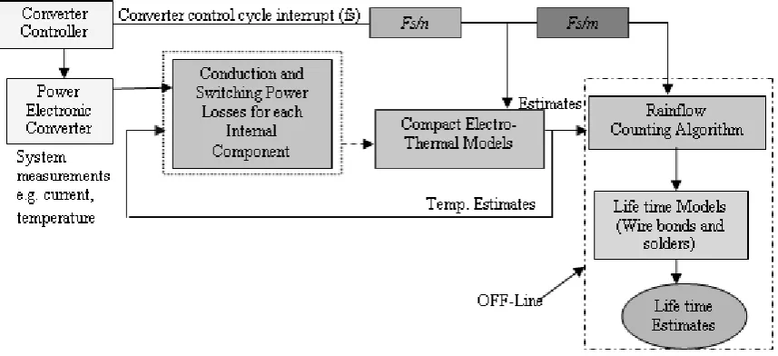
Figure 7 shows a schematic of the complete life consumption prediction scheme including a real-time
[image:12.595.85.514.135.331.2]implementation of the compact electro-thermal model combined with off-line life time models.
Fig.7: Implementation of the compact thermal model combined with life time model approach.
To give an example of life consumption estimation, an off-line test case to estimate the life time of a
typical IGBT power module for a bond-wire failure is presented. The compact thermal model was
applied to a uniform sequence of current demand level over a period of one minute. The load cycling
profile has a uniform amplitude (170A) and frequency (1 Hz). A sample of this load is shown in Fig.
8. Real-time IGBT junction temperature estimates relevant to this load profile are shown in Fig. 9.
The temperature varies between a minimum of 52.4ºC and a maximum of 69.5ºC for this typical test.
As a result of these temperature variations (ΔT = 17.1ºC), the number of cycles to fail is calculated
using the wire lifetime model represented in equation (2). The life consumption of the
bond-wire of this example can be calculated as the proportion of the number of applied load cycles and the
applicable calculated number of cycles to fail as in equation (7). This gives life consumption of
5.09E-06 over a period of one minute, in other words, the expected life of this bond wire when exposed to
Fig.8. Sample of the load current profile applied Fig.9: Sample of the real time IGBT junction to the real time thermal model . temperature estimates (C).
IV. COMPARISON OF LIFE ESTIMATES FOR REGULAR PASSIVE AND POWER CYCLING
Failures of different potential points of the power module such as the wire-bonds and the substrate-
solder have different physical driving mechanisms and will thus exhibit different wear-out rates in
different applications. In many applications the power modules run under conditions of continuous,
variable power cycling and/or thermal cycling where both the bond-wire and the substrate-solder are
affected differently by the converter modulation frequency and by environmental temperature
fluctuations. The ultimate failure mechanism may thus be a function of the in-service conditions and
it is therefore important to be able to separate the prospective failure mechanisms during any
accelerated life testing. In this study we investigate the response of bond-wire and substrate-solder
life expectancy to temperature variations induced by both load (power) cycling and environmental
temperature (passive) cycling. We demonstrate that it is possible to establish test methods that allow
isolation of the two failure mechanisms and further define test conditions that permit testing to failure
in a minimum elapsed time. This is useful in the design of accelerated life and qualification tests for
power modules and hence power electronic converters.
A. Effect of Power(Active) Cycling
The effect of power cycling on the real-time temperature estimates and hence the life consumption of
power modules can be studied for both the wire-bond and substrate-solder failure over a range of
Tem
p
era
tu
re
(
power cycling frequencies. The previously mentioned compact thermal model was implemented to
obtain the temperature variations over each operating power cycling frequency within the range 1mHz
and 100Hz for both the junction and the substrate-solder. The real-time thermal model was employed
with a fixed amplitude sinusoidal load current of 100A applied to the half bridge IGBT module
embedded in the constructed test rig shown in Fig. 6 with a constant coolant temperature of 40ºC.
The life time models for the wire-bond (equation 2) and substrate-solder (equation 3, 4 and 5) were
implemented offline using the estimated junction and substrate-solder temperature-time data
respectively. Life consumption was then calculated for the range of the load frequencies. Different
observations were obtained for different power cycling frequencies for both failure mechanisms.
Fig.10 illustrates the test result with 100A uniform sinusoidal load current applied over a range of
[image:14.595.201.396.368.529.2]power cycling frequencies.
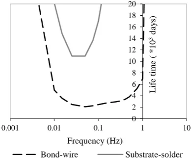
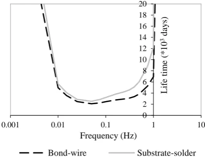
Fig. 10: Effect of power cycling frequencies on the life time of the power module at 100A sinusoidal load current
In this figure it is notable that the life time of both the wire-bond and the solder-substrate decreases
with increasing power cycling frequency until it reaches its minimum at 0.05Hz, at which the
bond-wire life is 2084 days. After that, the life time curve increases continuously as the power cycling
frequency is increased. The same trend is observed for the substrate-solder layer and it takes a
0 2 4 6 8 10 12 14 16 18 20
0.001 0.01 0.1 1 10
L
if
e
ti
m
e
(
*
1
0
3d
ay
s)
Frequency (Hz)
minimum time of about 10925 days to fail. This means that under power cycling the substrate-solder
layer always fails later than the bond-wire.
The accuracy of these observations is determined by the accuracy of the real-time temperature-time
data and by the accuracy of the wear-out models for the bond wire and substrate solder. . In [48],
good agreement (maximum error of a few%) was demonstrated between the estimated and measured
temperature-time data for both observable and hidden interfaces, providing confidence that these
estimates can be used to drive an appropriate PoF model. Regarding the PoF models, the variability
and limited availability of experimental reliability data coupled with limitations in the physical
models employed, are likely to result in much larger sources of error.
IGBT power modules are increasingly used in high power applications and they can be driven by
high load currents. It is interesting to note that different load conditions affect the wear-out
mechanisms differently. Hence, it is important to investigate the effects of different load currents on
the life time of the power module under different power cycling conditions. Virtual life time tests
were made using different values of experimental load current for both the bond-wire and the
substrate-solder applied to the system in Fig.6. For a 170A sinusoidal uniform load profile, the tests
showed that the higher the load current the higher the temperature variations would be for both the
junction and the substrate-solder temperatures. Compared with the results obtained in Fig. (10); the
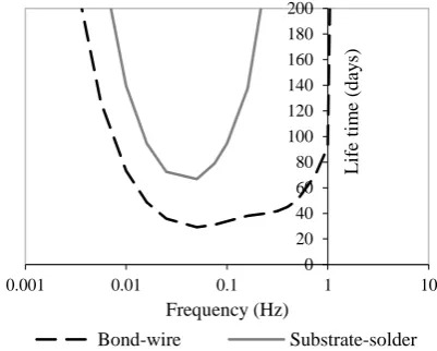
illustrations in Fig (11) showed that with load current of 170A, the time to fail for both the wire-bond
and the solder-substrate is lower. It is observed that life time estimate reaches its minimum at 0.05Hz
where the life time estimation for the wire-bond is 196 days. The same tendency is observed for the
substrate-solder layer but it takes longer to fail at about 577 days. If the same tests were repeated with
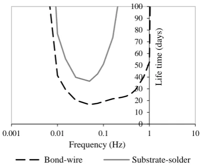
300A load profile, it is shown that the expected life time of the wire-bond will not exceed 29 days at
0.05 Hz followed by the solder-substrate which fails later after 66 days at the same frequency (Fig.
Fig. 11: Effect of power cycling frequencies on the life time of the power module using 170A sinusoidal load current.
Fig. 12: Effect of power cycling frequencies on the life time of the power module using 300A sinusoidal load current.
A clear explanation for these results is that higher load current produce more losses thus resulting in
higher module temperatures and lower life expectancy. In the case of power cycling tests, the
substrate-solder temperature fluctuations are always lower than the junction temperature which makes
the wire-bonds more susceptible to failure. Similar observations can be made in the case of the higher
temperature variations caused by using a 350A load current under the same power cycling
frequencies. Fig. (13) shows that the wire-bond life time will be no more than 16 days followed by
the substrate-solder which fails in a predicted 36 days.
0 2 4 6 8 10 12 14 16 18 20
0.001 0.01 0.1 1 10
L
if
e
ti
m
e
(*
1
0
2 d
ay
s)
Frequency (Hz)
Bond-wire Substrate-solder
0 20 40 60 80 100 120 140 160 180 200
0.001 0.01 0.1 1 10
L
if
e
ti
m
e
(d
ay
s)
Frequency (Hz)
[image:16.595.197.398.291.452.2]Fig. 13: Effect of power cycling frequencies on the life time of the power module using 350A sinusoidal load current.
From the above tests, it is clear that the both the load current amplitude and frequency have a dramatic
impact on the time to failure for the wire-bond and substrate-solder failure modes. Wire-bond failure
is always the dominant mechanism and the minimum elapsed time to failure occurs at a frequency of
0.05Hz for the power module and cooler combination used in these tests.
B. Effect of Thermal (Passive) Cycling
Ambient or thermal cycling means that both the bond-wire and substrate-solder typically experience
the same temperature variations. For the purposes of accelerated life testing, passive cycling over a
range of different cycling frequencies involves mounting the module on a low thermal resistance
cold/hot plate whose temperature can be modulated. This condition can be easily enforced in the
laboratory, although it is unlikely to be seen in service where the time-scale for ambient temperature
fluctuations is typically much longer and temperature distributions imposed by power cycling and
passive cycling will in general be different.
Life-time consumption or remaining life can thus be studied using the same methodology as for power
cycling, the only difference being that the life time models for both the bond wire and substrate-solder
(equation (2), (3) and through to equation (5) ) are applied using the same temperature variations.
0 10 20 30 40 50 60 70 80 90 100
0.001 0.01 0.1 1 10
L
if
e
ti
m
e
(d
ay
s)
Frequency (Hz)
To study the effect of different load profiles, the tests were conducted using the junction temperature
variations obtained from applying a range of different uniform sinusoidal load currents with 100A,
170A, 300A and 350A respectively to the same test rig used and illustrated earlier in Fig. 6 with the
same coolant temperature at 40ºC.
The life time curves, obtained for an equivalent 100A sinusoidal uniform load profile, are shown in
Fig. 14 and illustrate a minimum elapsed life as the frequency range approaches 0.05Hz. Life times
for both failure mechanisms are now closer to one another compared to the power cycling tests: the
life time of the bond wire is at its minimum of 2084 days while it is 2529 days for the
substrate-solder. The solder- substrate failure rate is accelerated because it is now subject to the same
temperature range as the juntion.
When an equivalent 170A sinusoidal uniform load profile was applied, the life time expectancy for
the substrate- solder failure mechanism again approaches a minimum at 0.05Hz frequency but in this
[image:18.595.194.398.423.580.2]case it fails before the wire bond after approximately 139 days (Fig.15).
Fig. 14: Effect of passive thermal cycling frequencies (same applied ΔT) on life time of the power module at an equivalent 100A sinusoidal load current
0 2 4 6 8 10 12 14 16 18 20
0.001 0.01 0.1 1 10
L
if
e
ti
m
e
(*
1
0
3d
ay
s)
Frequency (Hz)
Fig. 15: Effect of passive thermal cycling frequencies (same applied ΔT) on life time of the power module at an equivalent 170A sinusoidal load current
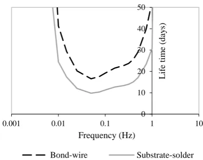
The tendency of the substrate solder to fail first becomes more apparent as the thermal cycling range
is increased, as clearly illustrated by the results obtained from temperature profiles equivalent to the
300A and 350A load profiles. Figs. 16 and 17 show respectively the life time curves for the
substrate-solder and wire bond for temperature profiles equivalent to 300A and 350A. In both cases the module
life is dominated by the substrate solder with the minimum life (17 days at 300A and 10 days at 350A)
occurring at a cycling frequency of 0.05Hz.
Fig. 16: Effect of passive thermal cycling frequencies (same applied ΔT) on life time of the power module for an equivalent 300A sinusoidal load current
0 100 200 300 400 500 600
0.001 0.01 0.1 1 10
L
if
e
ti
m
e
(d
ay
s)
Frequency (Hz)
Bond-wire Substrate-solder
0 20 40 60 80 100 120 140 160 180 200
0.001 0.01 0.1 1 10
L
if
e
ti
m
e
(d
ay
s)
Frequency (Hz)
Fig. 17: Effect of passive thermal cycling frequencies (same applied ΔT) on life time of the power module for an equivalent 350A sinusoidal load current
C. Discussion
Power cycling and thermal (passive) cycling tests, conducted at accelerated rates for life time
determination are fundamental to the design and qualification of power electronic modules. It is
clearly desirable that such tests be designed: a) to allow discrimination between the various failure
mechanisms and b) so that they can be completed in the minimum elapsed time. During power
cycling, heat diffuses from the heat source (semiconductor die(s)) through the packaging materials to
the heat sink. Each element of the module, including the wire bonds and substrate solder, responds
differently to the changing power input. Points closest to the heat source, such as the bond wires,
respond most quickly, while those further from the source, such as the substrate solder, respond more
slowly. At high frequencies the oscillating heat flux penetrates only a small distance from the heat
source (dies), meaning that the temperature fluctuations at all locations are severely attenuated, the
attenuation increasing as the distance from the source increases, At very low frequencies the
temperature responses at the various points attain their steady state values, reflecting the effective
thermal path resistances. At all frequencies, temperature variations at the heated junction and wire
bonds will be largest while those closer to the heat sink (e.g. substrate solder) will be smaller. This
effect is accentuated at high frequencies. As a consequence, the wire bonds see a much larger
0 10 20 30 40 50
0.001 0.01 0.1 1 10
L
if
e
ti
m
e
(d
ay
s)
Frequency (Hz)
amplitude temperature cycle and thus wear-out more quickly than the substrate solder as illustrated
in Figs. 10-13. Note that at low frequencies the ratio of expected life for wire bonds to substrate solder
is approximately constant, reflecting the quasi-steady-state thermal conditions. At higher frequencies
this ratio increases because the effects of thermal diffusion reduce the temperature fluctuations at the
substrate solder.
During thermal (passive) cycling, heating and cooling occurs through the base-plate of the module.
Since the base-plate has a high thermal mass the temperatures at the base-plate-substrate interface
(i.e. the substrate solder) respond relatively slowly to the applied heat flux input. Indeed, the time
constants characterizing the thermal path between the junction and the substrate are so much smaller
than those characterizing the base-plate that all of these layers respond virtually simultaneously to
changes in heat flux at the heat-sink side of the base-plate. In addition, since relatively little heat is
conducted away from the upper (die) surface of the module, the steady-state temperatures of the
wire-bond and substrate solder will be the same and so the thermal response will be almost identical over
a wide frequency range (up to a frequency where the time constants of the substrate become
significant).
From the results presented it is clear that different wear-out mechanisms can be made to dominate by
the correct choice of test (power cycling vs. thermal cycling) and cycling frequency. It is also clear
that the total elapsed test time can be minimized by optimum choice of cycling frequency; in this case
close to 0.05 Hz. In general, the frequency at which this occurs will be determined by the physical
structure and resulting thermal dynamics of the module and the thermal management system applied
during testing.
The foregoing sections have described a method to determine the wear-out rates and life consumption
for the dominant failure mechanisms under prospective in-service and test conditions. This method
converters in which a range of different failure mechanisms (i.e. wire-bond and substrate-solder ) can
act together to determine product life. The results of such tests can then be related to prospective
in-service conditions by applying the same methods to estimate temperature variations and expected
life.
V. CONCLUSION
A combination of reduced-order thermal model and physics-of-failure based models has been used to
quantify the wear-out rates and life consumption for two common power module wear-out
mechanisms (bond-wire lift-off and substrate-solder failure mechanisms) under prospective
in-service and life test conditions. Temperature estimates for interconnects, such as bond wires, and
bonded interfaces, such as solder layers, were combined with mechanical stress models and
physics-of-failure-based life consumption models to provide predictions of remaining useful life and the
anticipated failure mode.
The models have been employed to study the effects of power cycling and thermal (passive) cycling
on bond wire lift off and the substrate-solder failure mechanism acrossa range of load currents (power
cycling), temperatures (passive cycling) and cycling frequencies. For power cycling, failure of the
bond-wire was identified as the dominant failure mechanism because it is subject to the greatest
temperature variation. Conversely, under passive or ambient thermal cycling the substrate-solder can
be expected to fail first since in this case both bond-wire and substrate-solder see similar temperature
variations. In both power and thermal cycling tests, the minimum elapsed time to failure was
determined to occur at a cycling frequency of 0.05 Hz, representing a trade-off between the achievable
temperature range and time taken to complete each cycle.
By applying the methods presented, an appropriate test method (power cycling vs. thermal cycling)
and cycling frequency can be selected to isolate particular failure mechanisms and yield test results
mechanisms and lifetime under prospective in-service conditions and so make it possible to design
accelerated life tests that target the identified dominant failure mechanism.. Finally, the models can
be readily implemented in real-time and thus may be used to predict remaining useful life in service,
as part of a health management scheme. The main limitation of the method arises from uncertainty in
the physics-of-failure models used to determine the wear-out rates.
VI.REFERENCES
[1] K. Feldman, T. Jazouli, and P. Sandborn, “A methodology for determining the return on investment associated with prognostics and health management,” IEEE Trans. on Reliability, vol. 58, no. 2, pp. 305-316, June 2009.
[2] G. Haddad, P.A. Sandborn, T. Jazouli, M.G. Pecht, B. Foucher and V. Rouet, “Guaranteeing high availability of wind turbines,” ESREL Conference, Troyes, France, September 18-22, 2011.
[3] Y. Xiong and X. Cheng, “Prognostic and warning system for power-electronic modules in electric, hybrid electric, and fuel-cell vehicles,” IEEE Transactions on Industrial Electronics, vol. 55, June 2008.
[4] A. Hamidi, N. Beck, K. Thomas, and E. Herr, “Reliability and lifetime evaluation of different wire bonding technologies for high power IGBT modules,” Microelectronics Reliability, vol. 39, pp. 1153-1158, 1999.
[5] T. Panchwagh, F. P. McCluskey, G. Kromholtz, and G. Wenzel, “Reliability of surface mount capacitors subjected to wave soldering,” International Journal of Microelectronics Packaging, vol. 1, no. 2, pp. 71-81, August 1998.
[6] J.L. Fock-Sui-Too, B. Chauchat, P. Austin, M. Mermet-Guyennet, and R. Meuret, “Performance and reliability testing of modern IGBT devices under typical operating conditions of aeronautic applications,”
Microelectronics Reliability, vol. 48, pp1453-1458, 2008.
[7] F. P. McCluskey, D. Das, J. Jordan, L. Condra, T. Torri, J. Fink and R. Grzybowski, “Packaging of electronics for high temperature environments,” International Journal of Microcircuits and Electronic Packaging, vol. 20, no. 3, p. 409. Third Quarter 1998. Adapted from Proceedings of the Int’l Electronics
Packaging Society Conference, held in Austin, TX, Sep 29- Oct 1, pp. 143 – 155, 1996.
[8] B. Harris, Fatigue in Composites. Woodhead publishing Ltd, Cambridge UK, ISBN 1 85573 608 X, 2003.
[9] H. Ye, M. Lin, C. Basaran, “Failure modes and FEM analysis of power electronics packaging,” Journal of Finite Elements in Analysis and Design, vol. 38, pp. 601 – 612, 2002.
[10] M. H. Azarian, R. S.R. Kumar, N. PatiL, A. Shrivastava, and M. Pecht, “Applications of health monitoring to wind turbines,” 24th Internationl Conference on Condition Monitoring and Diagnostics Engineering Management, , Stavanger, Norway, 30 May -1 June 2011.
[11] K. Upadhyayula, and A. Dasgupta, “Accelerated stress testing of surface-mount interconnects under combined temperature and vibration loading,” Chapter accepted in Accelerated Stress Testing Handbook for
[12] U.S Department of Defense (DoD), MIL-HDBK 217, Military Handbook for Reliability Prediction of Electronic Equipment, version A, Washington DC, 1965.
[13]Telcordia Technologies, Special Report SR-32, Reliability Prediction Procedure for Electronic Equipment, issue 1, Telcordia Customer Service. Piscataway, NJ, 2001.
[14] W. Denson, “A Tutorial: PRISM,”RAC Journal, pp. 1 -6, 1999.
[15] FIDES Group, FIDES Guide Issue A, Reliability Methodology for Electronic Systems. 2004.
[16] M. G. Pecht, Prognostics and Health Management of Electronics. New York, NY, USA: Wiley-Interscience, 2008.
[17] N. Vichare and M. Pecht, “Prognostics and health management of electronics,” IEEE Transactions on Components and Packaging Technologies, vol. 29, no. 1, March 2006.
[18] P. Lall, M. Islam, M. Rahim and J. Suhling, “Prognostics and health management of electronic packaging,” IEEE Trans. Components and Packaging Technologies, vol. 29, no. 3, pp. 666-675, 2006.
[19] Oukaour et al., “Ageing defect detection on IGBT power modules by artificial training methods based on pattern recognition,” Microelectronics Reliability, 2011.
[20]M. Pecht, and F. Nash, “Predicting the reliability of electronic equipment,” Proceedings of the IEEE, vol. 82, no. 7, pp. 992-1004, 1994.
[21] A. Dasgupta, D. Barker, and M. Pecht, “Reliability prediction of electronic packages,” Journal of the Institute of Environmental Sciences, vol. 33, no. 3, pp. 36-45, 1990.
[22] N. Vichare, P. Rodgers, V. Eveloy and M. Pecht, “Environment and usage monitoring of electronic products for health (reliability) assessment and product design,” IEEE Workshop and Accelerated Stress Testing & Reliability, Austin ,2005.
[23] M. Cushing, D. Morton, T. Stadterman, and A. Malhotra, “Comparison of electronics reliability assessment approaches,” IEEE Transaction on Reliability, vol. 42, no. 4, pp. 542-546, 1993.
[24] N. Patil et al., “A Prognostic approach for non-punch through and field stop IGBTs,” Microelectronics Reliability, vol. 52, issue 3, pp. 482-488, March 2012.
[25] G. Niu, S. Singh, S.W. Hollandand M. Pecht, “Health monitoring of electronic products based on Mahalanobis distance and Weibull decision metrics,” Microelectronics Reliability, vol. 51, Issue 2, pp. 279-284, February 2011.
[26] M. Pecht, A. Dasgupta, D. Barker, D. and C. Leonard, “The reliability physics approach to failure prediction modeling,” International Journal of Quality and Reliability Engineering, vol. 6, no. 4, pp. 267-274, 1990.
[27] F. P. McCluskey, E.B. Hakim, J. Fink, A. Fowler, and M. Pecht, “Reliability assessment of electronic components exposed to long-term non-operating conditions,” IEEE Transactions on Components, Packaging and Manufacturing Technology, vol. 21, No. 2, part A, pp. 352-360, June 1998.
[29] H. Lu, W.S. Loh, T. Tilford, C. Bailey, C.M. Johnson, “Reliability of power electronic modules,”
Proceedings of IPACK2007, ASME InterPACK ‘07, July 8-12, 2007.
[30] N. Patil, D. Das, K. Goebel, and M. Pecht, “Identification of failure precursor parameters for insulated gate bipolar transistors (IGBT’s) ,” IEEE International Conference on Prognostics and Health Management (PHM), Denver, CO, USA, October 6-9, 2008.
[31] C. Bailey, H. Lu,C. Yin, S. Ridout, “Predictive reliability, prognostics and risk assessment for power modules,” Proceeding of the CIPS conference, Germany, 2008, pp.19-25.
[32] B. W. Ricks and O. J. Mengshoel, “Methods for probabilistic fault Diagnosis: An electrical power system case study,” In Proc. of the First Annual Conference of the Prognostics and Health Management Society (PHM-09), San Diego, CA, 27 September – 1 October, 2009.
[33] N. Patil, D. Das, K. Goebel, and M. Pecht, “Failure precursors for insulated gate bipolar transistors,”
Proceedings of the 1st International Conference on Prognostics and Health Management, Denver, CO, USA, October 6-9, 2008.
[34] M. Musallam and C.M. Johnson, “Monitoring through-life thermal path degradation using real-time thermal models,” IEEE Power Electronics Specialists Conference – PESC, Rhodes Greece, June 15-19, 2008.
[35] IEEE Standard 1413-2002, IEEE Guide for selecting and using reliability predictions based on IEEE 1413, IEEE, NY, 2002 .
[36] M. Pecht and A. Dasgupta, “Physics of failure: An approach to reliable product development,” Journal of the Institute of Environmental Sciences, vol. 38, pp. 30-34, 1995.
[37] N. Patil, D. Das, C. Yin, H. Lu, C. Bailey and M. Pecht, “A Fusion approach to IGBT power module prognostics,” 13th International Conference on Thermal, Mechanical and Multi-Physics Simulation and Experiments in Microelectronics and Microsystems (Eurosime), Delft, Netherlands, 2009, pp. 215 – 220.
[38] D. Chamund, C. Rout, “Reliability of high power bipolar devices,” Application Notes, October 2009 [online]. Available:http://www.dynexsemi.com/assets/Application_Notes/DNX_AN5945.pdf.
[39] H. Lu, C. Bailey and C. Yin, “Design for reliability of power electronics modules,” Microelectronics Reliability, vol. 49, pp. 1250-1255, 2009.
[40] M. Alam, H. Lu and C. Bailey, “Fracture Mechanics Analysis of Cracks in Solder Joint Intermetallic Compounds,” IEEE Electronics System Integration Conference (ESTC), Greenwich, London, UK, 2008, pp. 757-763.
[41] H. Lu, W-S. Loh, C. Bailey and M. Johnson, “Computer modelling analysis of the globtop’s effects on aluminium,” IEEE Electronics System Integration Conference (ESTC), Greenwich, London, UK, 2008, pp.1369 – 1375.
[42] C. Bailey, T. Tilford, and H. Lu, “Reliability analysis for power electronics modules,” 30th International Spring Seminar on Electronics Technology, ISSE2007, Cluj-Napoca, Romania, 2007.
[43] L. Coffin, Jr., Met. Eng. Q., vol. 3, pp. 15-24, 1963.
[45] C.F. Dunn and J.W. McPherson, “Temperature cycling acceleration factors in VLSI applications,” IEEE-IRPS Proceedings, pp. 252, 1990.
[46] H. Lu, T. Tilford, C. Bailey and D.R. Newcombe, “Lifetime prediction for power electronics module substrate mount-down solder interconnect,” Proceeding of the International Symposium on High Density Packaging and Microsystem Integration, China, 2007, pp. 40-45.
[47] T. Wernicke, A. Middendorf, S. Dieckerhoff, S. Guttowski and H. Reichl, “Test system for the reliability management of power modules,” Proceeding of the CIPS conference, Germany, 2008, pp.49-53.
[48] M. Musallam and C.M. Johnson, “Real-time compact thermal models for health management of power electronics,” IEEE Power Electronics Transactions, vol.25, issue 6, pp. 1416 – 1425, June 2010.
[49] M. Musallam and C.M. Johnson, “Extraction of efficient thermal models for life limiting interfaces in
power modules,” the 5th International Conference on Integrated Power Electronics Systems- CIPS, Nuremberg, Germany, March 11-13, 2008.
[50] Dspace Syatems, [Online].Available:http://www.dspace.com/en/ltd/home.cfm
[51] ASTM E 1049-85 (Reapproved 1997), Standard practices for cycle counting in fatigue analysis, Annual Book of ASTM Standards, vol. 03.01, pp. 710-718, Philadelphia, USA, 1999.
[52] M. Musallam, C.M. Johnson, C. Yin, H. Lu and C. Bailey, “In-service life consumption estimation in power modules,” the 13th International Conference on Power Electronics and Motion Control September (EPE PEMC), Poznan, Poland, September 1-3, 2008.
[53] Y. Kondo, “Fatigue under variable amplitude loading,” Comprehensive Structural Integrity, vol.4, pp. 253-279, 2003.