Linear and Nonlinear Time Domain Block Equalizers
on MIMO Frequency Selective Channels
Cong Li, Yasunori Iwanami
Department of Computer Science and Engineering, Graduate School of Engineering, Nagoya Institute of Technology, Nagoya, Japan
Email: [email protected], [email protected]
Received January 24, 2013; revised February 13, 2013; accepted February 21, 2013
ABSTRACT
Single-Carrier (SC) transmission with the same bandwidth as Multi-Carrier (MC) transmission (such as OFDM) may have far shorter symbol duration and is considered to be more robust against time selective fading. In this paper, we proposed the novel equalization and signal separation schemes in time domain for short block length transmission, i.e.,
Block Linear Equalization (BLE) and Block Nonlinear Equalization (BNLE) on MIMO frequency selective fading channels. The proposed BLE uses the MMSE based inverse matrix in time domain and the BNLE utilizes the QRD-M (QR Decomposition with M algorithm) with appropriate receiver complexity. We compared the computational com- plexity among the conventional SC-FDE (Frequency Domain Equalization) scheme and the proposed equalizers. We also used the Low-Density Parity Check (LDPC) decoder concatenated to the proposed BLE and BNLE.
Keywords: MIMO Frequency Selective Fading Channel; ISI; IAI; Time Domain Block Equalizer; BLE; BNLE
1. Introduction
For high speed mobile communications with wide trans- mission bandwidth, Inter-Symbol Interference (ISI) due to multipath propagation must be compensated. For the ISI compensation, the channel equalization such as FDE with Guard Interval (GI) in OFDM can effectively equalize the frequency selective fading [1,2]. However, with increas-ing number of subcarriers in OFDM, the symbol duration becomes large and the long symbol duration causes the problem of durability against time selective fading. Al-though it is considered that OFDM can cope with time selective fading with some compensation technique such as V-BLAST detection for each subcarrier [3], the long symbol duration in OFDM is essentially difficult to adapt the receiver for rapid time selective fading. On the other hand, SC transmission with the same transmission band-width as OFDM is able to have much shorter symbol duration than OFDM and the short time block transmis-sion with small number of symbols is strong against time selective fading. In [4], Turbo encoded MIMO SC transmission scheme is introduced. The authors used the FDE to cancel the ISI and IAI by decomposing the fre-quency selective channel to the flat Rayleigh fading channel accommodated at each frequency index. The receiver processes the received signal between the FDE and Turbo decoder iteratively. However, in compensating the ISI for SC block transmission with small number of
symbols, the FDE is not efficient, because the FDE with small number of FFT points cannot effectively equalize the channel frequency selectivity. Accordingly, instead of FDE, the time domain equalization is effective for the short block length with small number of symbols and has been considered in [5-11]. In [5], the soft canceller with MMSE filter compensates the ISI and IAI in time domain, however, it needs soft replicas provided by the turbo de- coder and the error correction encoding at the transmitter is required. In [6,7] the author proposed the method using Maximum Likelihood Detection (MLD) with successive cancellation, where the simulated results are all based on 2-tapped delay line model. However, as the number of multipath is larger than 2 actually, the amount of compu-tation will dramatically increase when the number of multipath becomes large. In order to solve this problem, the authors introduced the oversampling technique, but this leads to extremely high synchronization requirements for the whole system.
lizer. However, those receivers can basically work as the sequential receiver.
In this paper, we propose the novel linear and nonlinear block equalization schemes in time domain for the SC transmission with short block length, where the CSI is only available at the receiver. We firstly defined the ex-tended MIMO channel matrix H over the space and time domain for MIMO frequency selective channels. By carefully designing the transmit signals, we proposed several novel signal separation and equalization receiver structures using block processing in time domain with small number of transmit symbols. From the simulation results, the proposed receivers showed the excellent BER characteristics compared with the conventional SC FDE receiver, especially when the block size is small. In addi-tion, we compare the computational complexity among SC-FDE, BLE, BNLE QRD-M and MLD, where we em-ploy the similar steps in the case of BNLE [QRD-M] [12]. In order to demonstrate or prove the feasibility of error correction encoding for the proposed schemes, we also applied the Low Density Parity Check (LDPC) code, which was originally proposed by Gallager [13] and has attracted much attention recently [14].
This paper is organized as follows. In Section 2, we introduce the system model on SISO and MIMO fre-quency selective channels. The proposed block equaliza-tion schemes will be described in Secequaliza-tion 3, where we proposed and compared the several linear and nonlinear block equalization receivers. In Section 4, the simula- tion results are shown. In Section 5, the conclusions are given.
Throughout the paper, we illustrate some of the nota-tions as follows; vectors and matrixes are expressed by the bold italic letters.
,Η†, TE H and
H
denote the expectation, pseudo-inverse, transpose and conjugate transpose of matrices, respectively.
2. System Description
We first introduce the SISO channel model on the fre-quency selective fading channel. The receive signal
r t
t kT t
,T
t
can be written as
k k
kr t I g
(1)where k and are the transmit signal
point at time k, overall channel impulse response
includ-ing pulse shapinclud-ing and transmit filters, the symbol dura-tion and the AWGN noise, respectively. The matched filter
,
I g t
g t is employed for the receive signal r t
k y
1
0 L
k l k l k
l
y h I n
and the symbol time sampling is made. The sampled signal is then passed through the noise whitening filter to get the receive signal point at time k
(2)
0, , 1
h ll Lwhere n
0, , 1
h l Ln
is the tap coefficient and k
[image:2.595.310.542.274.352.2] [image:2.595.357.490.643.718.2]is the independent complex Gaussian noise variable. Equation (2) is referred to as the tapped delay line model [15].
Figure 1 shows the delay profile of SISO multipath channel in the tapped delay line model, where we assume
that the tap coefficients l have i.i.d.
Rayleigh amplitude distributions.
We consider the spatial multiplexing system with T
transmit and nR receive antennas. We define the space-
time extended matrix to apply the block processing for the multipath channel model.
2 1
LThe extended matrix H with the size nR L nT
0 2 1
0 2 1
0 2 1
L L
L L
L L
can be written as follows.
h h h
H
h h h
h h h
0
0
(3)
where L is the number of multipath and
l 0, 2, ,L 1
l
h is the element matrix, which
fol-lows the quasi-static flat fading with the size of nRnT, i.e.,
1
11 12
2
21 22
1 2
T
T
T T R T
n
l l l
n
l l l
l
n n n n
l l l
h h h
h h h
h h h
h
ij
h
ij
h
(4)
where l is the l-th delay path gain from the j-th trans- mit antenna to the i-th receive antenna, and l follows the i.i.d. Rayleigh amplitude distribution. It is also as-
21 ij l
E h
sumed , i.e., the average channel gain is
normalized to one. The channel is assumed quasi-static,
i.e., the channel gains are static within a block length, but
change independently from block to block.
In this paper, we assumed that the extended channel matrix H is known at the receiver, i.e., the receiver has
the perfect Channel State Information (CSI) by sending training sequences just before the data block.
Using H, we obtain the extended input and output re-
0
h h1 hL1
t
0 T (L1)T
lationship given by
Y HX N
T1 2 k
. (5) where Y is the extended receive vector expressed as
k L k L
Y y y y
1, 2, , ynR
T1 xk L 1
(6)
and k k is the element receive sig-
nal vector at time k. X is the extended transmit signal
vector expressed as
k yk y
y
k L k
X x x (7)
and
x 1,x2, , xnT
T1 2 nk
1, 2, , nnR
H
1k k
x x
, i j
H
, , ,
, , ,
0 1 1
, ,
1 , 1 1
1
, ,
2 , , 2 2
0 1
, ,
1 1
, ,
, 0
0
0 0
i j i j j i j
CP
i j i j i j
L
i j j i j
i j
i j j i j
i j i j
L
i j i j
L
i j j i j
N i j N N
h h h
y x n
h
y x n
h h
h h
y x n
h
k k k k is the element transmit sig-
nal vector at time k. N is the extended receive noise
vec-tor expressed as
x
k L k L
N n n (8)
where k k is the element additive
white Gaussian noise vector at time k. It also holds the
following equations and
.
k nk n
n
0H
k k
E n n N
H
0,k k
E x n E
3. Block Linear and Nonlinear Equalizers
for MIMO Quasi-Static Frequency
Selective Fading Channels
This paper focuses on the signal separation and equaliza-tion of MIMO SC transmission schemes. In order to il-lustrate the BER performances of proposed schemes clearly, it is necessary to give a brief introduction of MIMO SC-FDE as the reference scheme.
3.1. MIMO SC-FDE
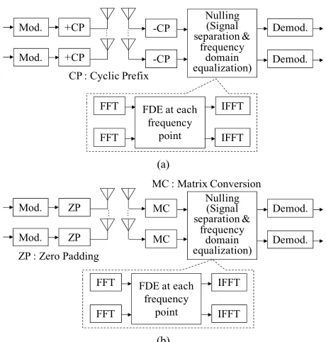
In Figure 2, the equivalent baseband model of transmit-ter and receiver in MIMO SC-FDE on the MIMO quasi- static frequency selective channels is depicted. Figures 2(a) and (b) show the MIMO SC-FDE with CP (Cyclic Prefix) and the one with ZP (Zero Padding) named as MIMO SC-FDE-CP and MIMO SC-FDE-ZP, respec-tively. At each transmit antenna, the data bit stream is grouped into the block. After periodically inserting the CP or ZP, all the blocks are transmitted simultaneously from the multiple transmit antennas over the frequency selective channels using the same carrier frequency. At the receiver, the CP is removed and the ZP is processed by the matrix conversion. Then the received data are converted into frequency domain by using Fast Fourier Transform (FFT). Frequency Domain equalization (FDE) are then performed. Finally, the Inverse Fast Fourier Transform (IFFT) is used to convert the frequency do-main signal to the time dodo-main for demodulation.
3.1.1. MIMO SC-FDE-CP
The MIMO SC-FDE-CP scheme is illustrated in Figure 2(a). The transmit and receive vector representations with
the channel expression of CP from transmit antenna j
to receive antenna i in the FFT frame is denoted as
Y H X N
, i j y
, i j l h j
(9)
where k is the receive signal at time k from the
transmit antenna j to the receive antenna i, is the
complex channel gain of the l-th delay path, xk is the
transmit symbol at time k from the transmit antenna j and
k is the complex Gaussian noise at time k. We have
set the block length to N symbols. The channel matrix
CP in (9) becomes the circulate convolution matrix
and the FDE can be done using FFT. ,
i j n
, i j
H
, i j
3.1.2. MIMO SC-FDE-ZP
The MIMO SC-FDE-ZP scheme is illustrated in Figure 2(b). The transmit and receive vector representation with the channel expression of ZP from the transmit
an-tenna j to the receive antenna is given by
H
i
, , ,
, 0
, , ,
1 1 1
, , ,
2 0 1 2
, ,
2
1 1
, ,
, 1
, ,
0
0
0
i j i j j i j
ZP i j
i j i j i j
i j i j j i j
j
i j i j
L
i j i j
N N
j i j
N L
i j i j
N ZP N ZP
h
y h n
y h x n
x
h h
y n
x h
y n
Y H X N
(10)
where each element in (10) is almost the same as in (9), but as shown in (10) the channel matrix i j,
ZP now
be-comes the linear convolutional matrix. Also the size of
receive vector is extended to due to the
zero padding.
H
, i j
Y NZP
3.2. Block Equalizer in Time-Domain
For the transmit signal vector in (7), we can expand its size arbitrary, i.e.
k L N 1 k N 1 k k L 1
X x x x x (11)
where N is again the number of symbols in a block.
Ac-cordingly, the sizes of extended transmit vector, channel matrix, receive vector and noise vector are expressed as
2L N 2
nT1,
L N 1
nR
2L N 2
nT,
LN1
nR1, and
L N 1
nR1, respectively.Nulling (Signal separation & frequency domain equalization) Demod. Demod. Mod. +CP Mod. +CP -CP -CP
CP : Cyclic Prefix
FDE at each frequency point FFT FFT IFFT IFFT (a) Mod. ZP Mod. ZP MC MC Demod. Demod. MC : Matrix Convers
ZP : Zero Padding
ion
FDE at each frequency point FFT FFT IFFT IFFT Nulling (Signal separation & frequency domain equalization)
[image:4.595.57.287.80.321.2] 1 1 1 1 1 1 (b)
Figure 2. Transmitter and receiver model of MIMO-SC- FDE. (a) SC-FDE-CP; (b) SC-FDE-ZP.
1 1 1
0 2 1
0 2 0 2 1 1 1 H H H
k N k
k N L
L L
L L
k N k
k N L
0 y y
h h h
h h h
h h n n H H k L k L k N k L L k L H 0 y y x x x h x n
L1
2
1 k L N
k k n n n (12)
In order to avoid the Inter-Block Interference (IBI) at the receiver, the transmit vector is processed by using Zero-Padding as shown in the Figure 3.
We insert zero symbols before and after the
signal vector separately. The receive vector in (12) can be written as
1 2 1 1 1 0 1 1 1 1 0 1 0 N L
k L N k N
L L k k k k
Y H X N
h y x h h h h y x h y x h h h 0 0 (13)
where HN is the extended channel matrix with
L N 1
nRNnT
1 †.
The transmit and receive models of the proposed time domain block equalizers are shown in Figure 4.
3.2.1. BLE (Block Linear Equalizer)
When the channel matrix is given as in (13), we can compensate the ISI and the IAI simultaneously by using Moore Penrose inverse matrix in the analogy of nulling operation as in MIMO flat fading channels.
The inverse matrix based on Zero Forcing (ZF) crite-rion is given by (14)
H H
ZF
Η H H H
†
Η
ˆ
(14)
where denotes the pseudo-inverse matrix of H. The pseudo-inverse matrix exists when the number of col-umns is less than or equal to the number of rows. The estimates of X, which is denoted as X, is given by
1ˆ
ZF ZF ZF
H H ZF ZF
X H Y H HX H N
H H H HX H N
X H N
(15)
Equation (15) means that the ISI and IAI due to the channel are completely equalized. However, the disad-vantage of ZF is that it suffers from the noise enhance-ment.
t
t
GI=0 kx
1 kx
kx
X
GI=0 ky
y
k1y
k2y
ky
k1y
k2Y
0
h h1 h0 h1
Information symbol vector
Demodulated symbol vector Transmit symbol Receive symbol
Y
1 kx
X
0 [image:4.595.62.288.367.516.2]h h1 h0 h1
Figure 3. Illustration of zero-padding to prevent IBI at re- ceiver on MIMO multipath channel (L = 2, N = 2).
+
H Y
Mod. Mod. ZP ZP Demod. Demod. ZP : Zero Padding
+
H Y
Mod. Mod. ZP ZP Demod. Demod. +
H Y+ H Y
Mod. Mod. ZP ZP Mod. Mod. ZP ZP Demod. Demod. Demod. Demod. ZP : Zero Padding
(a) M -a lgor it hm H
Q Y
Mod. Mod. ZP ZP Demod. Demod.
ZP : Zero Padding
M -a lgor it hm H
Q Y
Mod. Mod. ZP ZP Demod. Demod. M -a lgor it hm H
Q Y
Mod. Mod. ZP ZP Mod. Mod. ZP ZP Demod. Demod. Demod. Demod.
[image:4.595.333.515.424.526.2]ZP : Zero Padding (b)
[image:4.595.315.531.564.707.2]In order to circumvent the noise enhancement, the in-verse matrix solution with the MMSE (Minimum Mean Square Error) criterion is obtained as
† MMSE
1 2 H H n H H H I H
† H
ˆ
(16)
By multiplying MMSE by Y from the left hand side of (13), the estimates of X based on MMSE criterion can be obtained. The MMSE solution in (16) trades off the signal separation quality for the noise enhancement reduction through the small term of 2
n I 2 1 1 1 1 0 1 0 0 0
0 k M
L k k k y x h y x x h h h 1 1
T R
.
Next we simply discuss the BLE in SISO and SIMO cases. In SISO case, the channel input and output equa-tion is given by
1 1 1 0 1 2 1 0 0 0 L
k L M
L
k
k L M
k k h h h h h y n n n
Y HX N
(17)
where each element in (17) becomes scalar value and this
corresponds to n n for the element hL
1 n 2 1 1 1 0 1 0 k N L k k k 0 0 0 x h x y x h h h 1 N
T1 1 0
k L k k
in (4).
In SIMO case, the proposed BLE can also be applied, where the element in (13) becomes the vector with
R and the channel input and output expression is
given by 1 1 1 0 1 1 2 1 L
k L N
L
k
k L N
k k 0 0 0
Y HX N h y h h h y h n n n (18)
It is necessary to discuss a special case in SIMO with
the block size of . When the block size equals 1,
Equation (13) can be written as
Y HX N
y h h h x n
,1 ,1 ,2 ,2 , , , , R R i i i i
i i i i
i n i n
y h
y h
(19)
where the elements in (19) are represented as
x y h
y h x
MRC
(20)
From (19) and (20), the Maximum Radio Combining (MRC) is available and the weight vector is written as
H
w H (21) The received signal after the MRC is expressed as
MRC
1 2
path,antenna antenna 1 path 1
R
H H
n L
k k
h x n
Y w Y = H HX + H N
H
H H
(22)
It is observed that the term achieves the sum
of all the squared channel gains over all the receive an-tennas, and the full diversity with the order nR
L1
is obtained in this case.3.2.2. BNLE (Block NonLinear Equalizer)
In [6,7], the author proposed the idea of imaginary transmit antenna and employed the layered MLD detec-tion to avoid the ISI. However, the computadetec-tional com-plexity greatly increases when the number of receive antennas is large. Here we propose the QR decomposi-tion with an M-algorithm (QRD-M). It is expected that the great reduction in computational complexity can be achieved without degrading the performance when com-pared with full MLD.
The QR-decomposition of channel matrix H is ob-tained as
H QR (23)
L 1
R
1
Rwhere Q is the N n L N n
Nn Nn
unitary matrix, R is the T T upper triangular matrix and
H H
Q Q I. After multiplying Q
H H H H
Q Y Q QRX + Q N RX + Q N
ˆ
by the received sig-nal Y from the left hand side, we get
(24) X is given by
and the estimate
11 12 1, 1
22 2 1 , , ˆ 0 0 0 T T T T T T H H Nn H Nn Nn Nn Nn Nn
r r r x
r x r x r
X Q Y RX + Q N
From Equation (25), it is observed that by applying the tree search with the decoding order from xNnT to x1, we can calculate the Euclidian distance based branch metric and path metric of (26) and (27) respectively, for all the possible values of x ii
1, , NnT
.2
, 1
T
Nn
i j j j i
r x
stage stage 1
i bm
Branch metric :bmi yi (26)
Path metric :pmi (27)
The accumulated path metrics are then ordered. Only
M nodes with the smallest accumulated path metrics are
retained and the rest is deleted. The same procedure is applied to the nodes in the next layer and this process continues up to the first layer x1. In QRD-M algorithm,
the parameter M is used as the number of limit to the
maximum survived branches in the breadth-first tree al-gorithm. By setting M equal to different values, it can
provide different tradeoff solutions between the system performance and the complexity. The larger M value, the
better performance is obtained, however the larger com-plexity is required.
4. Computer Simulation
4.1. BLE and BNLE
In this section, we show the BER performance of the proposed schemes in MIMO, SIMO, and SISO quasi- static frequency selective channels. First we have com-pared the BER characteristics of BLE with the existing SC-FDE. The simulation conditions are shown in Table 1.
As shown in Figure 1, the multipath channel between each transmit and receive antenna is modeled as the tapped delay line with L taps spaced by symbol duration Ts and each tap gain follows the independent complex
Gaussian random variable with equal power, i.e., the
quasi-static multipath Rayleigh fading channel with equal delay path power has been assumed. Under the same simulation condition, we have made the
compari-son among the MIMO, SIMO, and SISO channels.
Fig-ure 5 shows the BER performance with nT = nR = 4, L =
[image:6.595.309.537.95.472.2]8 and we set the transmit block length to
Table 1. Computer simulation conditions for Figures 5-8.
Modulation QPSK
Channel coding None
Block size (=N) N = 16 (N = 1, 4, 16 for Figure 8)
FFT size 16
Zero padding size (Number of path-1) = 7
Cyclic prefix size (Number of path-1) = 7
Delay profile between each transmit and receive antenna
Equal power 8 paths with i.i.d. Rayleigh distribution Spacing
of delay path is Ts
M (M-algorithm) 1, 2, 4
1.E-05 1.E-04 1.E-03 1.E-02 1.E-01 1.E+00
0 2 4 6 8 10 12 14 16 18 20 22 24 26 28 30
B E R
SC-FDE-ZP with ZF SC-FDE-CP with ZF SC-FDE-ZP with MMSE SC-FDE-CP with MMSE BLE with ZF BLE with MMSE BNLE with QRD(M=1) BNLE with QRD(M=2) BNLE with QRD(M=4)
BE
R
16
N
[image:6.595.94.288.150.216.2]Average Eb/N0 [dB]/receive antenna
Figure 5. BER comparison of proposed time domain block equalizers on MIMO quasi-static frequency selective chan- nels (4 × 4 antennas).
full multipath diversity (the SISO case in equation (17) well supports this characteristic) and obtain the better BER performance by 5 - 8 dB at BER = 10−5 than the SC-FDE based on MMSE criterion. We can say, for the
short block length like , BLE and QRD-M show
the excellent performances among the compared schemes. In the case of BNLE with QRD-M with M = 1, we can
obtain the better BER performance than BLE with MMSE by about 1 dB. From the complexity aspects of QRD-M algorithm, we only consider the case of M = 1 in
the followings. 16
N . In
order to fairly compare the SC-FDE with the proposed schemes, we assume that the size of zero padding is 7 and the length of CP is i , and by the Section 3.2,
we insert
7
G
7 L1 zero symbols before and after the
transmit signal vector. Since ZF-FDE with CP scheme can completely eliminate the inter block interferences, it performs better than ZF-FDE with ZP, the latter suffers from noisy prefix copy and sometime leads to a loss in frequency diversity [16]. Using the inverse matrix, the proposed time domain QRD-M and BLE schemes get the
In Figure 6, the simulation results for SIMO channel are shown. The proposed scheme can improve the
aver-age b 0
In Figure 7, we give the simulation results for SISO channel. Comparing the SC-FDE with MMSE with the BLE with MMSE, the proposed BLE with MMSE exhib-its the better BER by 2 dB - 6 dB at BER = 10−5. How-
1.E-04 1.E-03 1.E-02 1.E-01 1.E+00
0 4 8 12
B ER
16 20
SC-FDE-1.E-05 1.E-04 1.E-03 1.E-02 1.E-01 1.E+00
0 4 8 12 16 20
B ER
BLE with MMSE, N=16
CP with ZF
SC-FDE-CP with MMSE BLE with MMSE, N=4
BLE with ZF BLE with MMSE, N=1
BLE with MMSE BNLE with QRD, N=16
BNLE with QRD-M BNLE with QRD, N=4
BER
BNLE with QRD,N=1
R
BE
[image:7.595.61.287.82.281.2]Average Eb/N0 [dB]/receive antenna
Figure 6. BER comparison of proposed time domain block equalizers on SIMO quasi-static frequency selective chan-nels (1 × 4 antennas).
1.E-05 1.E-04 1.E-03 1.E-02 1.E-01 1.E+00
0 4 8 12
B ER
16 20
SC-FDE-ZP with ZF SC-FDE-CP with MMSE BLE with ZF BLE with MMSE BNLE with QRD-M
BER
[image:7.595.311.536.85.281.2]Average Eb/N0 [dB]/receive antenna
Figure 7. BER comparison of proposed time domain block equalizers on SISO quasi-static frequency selective channels (1 × 1 antenna).
ever, these improvements are mainly brought by the ef-fect of MRC, which is only usable for the size of N = 1.
On the other hand, the SC-FDE with CP or ZP only uses the nulling operation, thus the receive powers from mul-tiple receive antennas are not fully combined for the sig- nal separation and equalization.
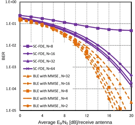
Figures 8 and 9 shows the BER performance for dif-ferent blocks length of N on SISO and MIMO quasi-
static frequency selective channels. The simulation result shows that the shorter block length can get more diver- sity gain in BLE and BNLE receivers. BLE suffers from the problem of exponential growth of computational complexity for calculating the inverse matrix when the
Average Eb/N0 [dB]/receive antenna
Figure 8. BER comparison between BLE with MMSE and BNLE with QRD-M for the different block length of N on SISO quasi-static frequency selective channels (1 × 1 an-tenna).
1.E-05 1.E-04 1.E-03 1.E-02 1.E-01 1.E+00
0 4 8 12 16 2
B E R
SC-FDE, N=8
BER
SC-FDE, N=16 SC-FDE, N=32 SC-FDE, N=64 BLE with MMSE , N=32 BLE with MMSE , N=16 BLE with MMSE , N=8 BLE with MMSE , N=4 BLE with MMSE , N=2
0
[image:7.595.61.287.330.528.2]Average Eb/N0 [dB]/receive antenna
Figure 9. BER comparison between BLE and SC-FDE with MMSE for the different block length of N on MIMO quasi- static frequency selective channels (4 × 4 antennas).
block size N becomes large. However, this problem does
not exist for SC-FDE because of the FFT processing in frequency domain. Accordingly the merit that the shorter block length exhibits the better BER in BLE seems bene- ficial to the short time block transmission under the fad-ing channel with time selectivity, because the short time block transmission is not very much influenced by the rapid time variation of the channel.
4.2. Analysis of Computational Complexity
[image:7.595.315.532.345.546.2]proposed schemes. The total numbers of real products and additions required for detecting one transmit symbol are derived as follows:
MIMO SC-FDE: 2
8nT 8nT 36log2N54
1
nR2NnT
1
2 1R T
n Nn
(28) MIMO BLE with ZF:
2 2
8 16
2 1
T T
R
N n Nn N L N L n
(29)
MIMO BLE with MMSE:
2 2
8 16
2 1
T T
R
N n Nn N L N L n
(30)
MIMO BNLE with QRD-M:
2
3 3 2
1 1
8 8 1 2
6 1 1 2 1
3 T
T R
T
Nn
T T
i
N n N L n
Q Nn M Q
Nn i Nn
1 1
1
T
R
Nn
i
N L n
M i
(31)
MIMO BNLE with full MLD:
2
10
4 1
QNn N L
Q N L
1
1 1 T
T R
Nn R
n Q n
Q
4
16, 8
T R
n n
N L
(32)
where N is the block length in BLE or BNLE and also is
the number of sample point in one block of MIMO SC-FDE. Q is the number of modulation levels and in
this paper we set Q = 4 (QPSK) and M = 1. The
compu-tational complexities under different parameters are shown as in Table 2.
From Table 2 we can say that the computational com-plexity increases with the order of SC-FDE < QRD-M < BLE ZF < BLE MMSE < full MLD. Especially, we found that SC-FDE has the least computational complex-ity in those four schemes. If enough memories to store the products and additions are available, the QRD-M scheme will show the best performance. In addition, in the case of short block length, BNLE with QRD-M needs less amount of computation comparing to SC-FDE.
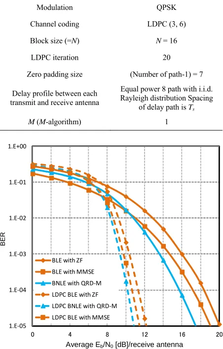
4.3. LDPC Coded BLE and BNLE
[image:8.595.306.536.98.232.2]In this section, we employed the LDPC encoding process in the transmitter to verify the feasibility of applying LDPC codes for BLE and BNLE. The sum-product algo-rithm is used to decode the LDPC code at the receiver. The simulation conditions are shown in Table 3. Figure 10 shows the BER performance of proposed LDPC coded
Table 2. Computational complexity/symbol.
Parameters Detection schemes
4
8, 8
T R
n n
N L
4
2, 8
T R
n n
N L
SC-FDE 250 214 142
BLE with ZF 126664 38728 5032
BLE with MMSE 126665 38729 5033
BNLE with QRD-M
(M = 1) 34125 9246 1849
[image:8.595.64.294.131.447.2]BNLE with full MLD 464 432 48
Table 3. Computer simulation conditions for Figure 10.
Modulation QPSK
Channel coding LDPC (3, 6)
Block size (=N) N = 16
LDPC iteration 20
Zero padding size (Number of path-1) = 7
Delay profile between each transmit and receive antenna
Equal power 8 path with i.i.d. Rayleigh distribution Spacing
of delay path is Ts
M (M-algorithm) 1
1.E-05 1.E-04 1.E-03 1.E-02 1.E-01 1.E+00
0 4 8 12 16 2
B ER
BE
R
BLE with ZF BLE with MMSE BNLE with QRD-M LDPC BLE with ZF LDPC BNLE with QRD-M LDPC BLE with MMSE
0
Average Eb/N0 [dB]/receive antenna
Figure 10. BER performances of proposed LDPC coded time domain block equalizers on MIMO quasi-static fre-quency selective channels (4 × 4 antennas).
schemes with nT = nR = 4 for MIMO quasi-static
[image:8.595.311.537.259.613.2]perform-ances by about 8 dB at BER = 10−5 compared with the corresponding uncoded schemes.
5. Conclusion
In this paper, we have proposed the time domain block linear and nonlinear equalizers for the signal separation and equalization of single carrier transmission on quasi- static frequency selective MIMO, SIMO, and SISO chan- nels. We have compared the BER characteristics of the proposed time domain equalizers with the conventional frequency domain SC-FDE. As a result, the proposed time domain block equalizers which utilize the zero symbol insertion and short block length transmission exhibit the better BER characteristics than the conven-tional SC-FDE. The proposed block nonlinear equalizer using QRD-M exhibits the best BER performance. From the computational complexity analysis, we have found that the proposed BNLE with QRD-M can greatly reduce the computational burden at the receiver compared with the one using full MLD. We also applied the LDPC code to the proposed block equalization schemes and the large coding gains were observed. The single carrier transmis-sion used in the proposed scheme is superior to the multi- carrier transmission like OFDM in PAPR and the signal separation and equalization in time domain for the pro- posed schemes is especially suited to the short block length transmission. As the single carrier transmission is robust against the non-linear amplifiers due to the low PAPR and the short block length transmission is not very much affected by the rapid channel variation, the pro- posed time domain equalizers is supposed to be useful for the high speed uplink transmissions under rapidly time varying frequency selective channels.
6. Acknowledgements
This study has been supported by the Scientific Research Grant-in-aid of Japan No. 24560454.
REFERENCES
[1] D. Falconer, S. L. Ariyavisitakul, A. Benyamin-Seeyar and B. Eidson, “Frequency Domain Equalization for Single- Carrier Broadband Wireless Systems,” IEEE Communica- tions Society Magazine, Vol. 40, No. 4, 2002, pp. 58-66. doi:10.1109/35.995852
[2] N. Le Khoa, H. Ishikami, Y. Iwanami and E. Okamoto, “A Consideration on the Improvement of LDPC Coded MIMO OFDM with Sphere Decoding through Outside It- erative Data Feedback,” IEICE Transactions on Commu- nications B, Vol. 91, No. 1, 2008, pp. 112-117.
[3] G. L. Stuber, J. R. Barry, S. W. McLaughlin, Y. Li, M. A. Ingram and T. G. Pratt, “Broadband MIMO-OFDM Wire- less Communications,” Proceedings of the IEEE, Vol. 92, No. 2, 2004, pp. 271-294.
doi:10.1109/JPROC.2003.821912
[4] J. Karjalainen, N. Veselinovic, K. Kansanen and T. Ma- tsumoto, “Iterative Frequency Domain Joint-over-Anten- na Detection in Multiuser MIMO,” IEEE Transactions on Wireless Communications, Vol. 6, No. 10, 2007, pp. 3620- 3631. doi:10.1109/TWC.2007.060037
[5] T. Abe and T. Matsumoto, “Space-Time Turbo Equaliza- tion in Frequency-Selective MIMO Channels,” IEEE Ve- hicular Technology Society, Vol. 52, No. 3, 2003, pp. 469-475. doi:10.1109/TVT.2003.813227
[6] D. K. C. So and R. S. Cheng, “Layered Maximum Likeli- hood Detection for V-BLAST in Frequency Selective Fading Channels,” IEEE 55th Vehicular Technology Con- ference, VTC Spring, Birmingham, 6-9 May 2002, pp. 135-139. doi:10.1109/VTC.2002.1002679
[7] D. K. C. So and R. S. Cheng, “Layered Maximum Likeli- hood Detection for MIMO Systems in Frequency Selec- tive Fading Channels,” IEEE Transactions on Wireless Communications, Vol. 5, No. 4, 2006, pp. 752-762. doi:10.1109/TWC.2006.1618924
[8] Y. Goto, Y. Iwanami and E. Okamoto, “Improvement of BER Characteristics with Eigen-Mode Transmission in MIMO Frequency Selective Channels,” IEICE Transac- tions on Communications, Vol. 90, No. 10, 2007, pp. 1045-1049.
[9] Y. Takahashi, Y. Iwanami and E. Okamoto, “A Com- parison of Time Domain Equalizers by Block Processing in SISO Single Carrier Transmission,” IEEE Interna- tional Symposium on Personal, Indoor and Mobile Radio Communications (PIMRC’07), Athens, 3-7 September 2007.
[10] Y. Takahashi, Y. Iwanami and E. Okamoto, “A Time Do- main Block Equalization Scheme on SIMO Frequency Selective Channels,” IEEE Region 10 Conference (TEN- CON’07), Taipei, 30 October-2 November 2007.
[11] S. Nakanobu, Y. Iwanami and E. Okamoto, “A Compara- tive Study on Time Domain Sequential Equalizer with MLD and MLSE Equalizer on MIMO Frequency Selec-tive Channels,” IEICE Transactions on Communications, Vol. E-93B, No. 11, 2010, pp. 3197-3202.
[12] C.-J. Ahn, “Parallel Detection Algorithm Using Multiple QR Decompositions with Permuted Channel Matrix for SDM/OFDM,” IEEE Transactions on Vehicular Techn- ology, Vol. 57, No. 4, 2008, pp. 2578-2582.
doi:10.1109/TVT.2007.913179
[13] R. Gallager, “Low Density Parity Check Codes,” IRE Transactions on Information Theory, Vol. 8, No. 1, 1962, pp. 21-28. doi:10.1109/TIT.1962.1057683
[14] D. J. C. Mackay and R. M. Neal, “Near Shannon Limit Performance of Low Density Parity Check Codes,” Elec- tronics Letters, Vol. 33, No. 6, 1999, pp. 457-458. doi:10.1049/el:19970362
[15] J. G. Proakis, “Digtial Communications,” 4th Edition, McGraw-Hill Inc, New York, 2001.
[16] Z. D. Wang, G. B. Giannakis and M. De Courville, “Cy- clic Prefixing or Zero Padding for Wireless Multicarrier Transmissions,” IEEE Transactions on Communications, Vol. 50, No. 12, 2002, pp. 2136-2148.