This paper is made available online in accordance with publisher policies. Please scroll down to view the document itself. Please refer to the repository record for this item and our policy information available from the repository home page for further information.
To see the final version of this paper please visit the publisher’s website. Access to the published version may require a subscription.
Author(s): Theodore L. Karavasilis and Choung-Yeol Seo Article Title: Seismic structural and non-structural performance
evaluation of highly damped self-centering and conventional systems Year of publication: 2011
Link to published article:
http://dx.doi.org/10.1016/j.engstruct.2011.04.001
Seismic structural and non-structural performance evaluation
of highly damped self-centering and conventional systems
Theodore L. Karavasilisa,* and Choung-Yeol Seob
aDepartment of Engineering Science, University of Oxford, OX1 3PJ, Oxford, UK
b
Bechtel Power Corporation, Frederick, MD 21703, USA
Abstract
This paper evaluates the seismic structural and non-structural performance of
self-centering and conventional structural systems combined with supplemental viscous
dampers. For this purpose, a parametric study on the seismic response of highly damped
single-degree-of-freedom systems with self-centering flag-shaped or bilinear elastoplastic
hysteresis is conducted. Statistical response results are used to evaluate and quantify the
effects of supplemental viscous damping, strength ratio and period of vibration on
seismic peak displacements, residual displacements and peak total accelerations. Among
other findings, it is shown that decreasing the strength of nonlinear systems effectively
decreases total accelerations, while added damping increases total accelerations and
generally decreases residual displacements. Interestingly, this work shows that in some
instances added damping may result in increased residual displacements of bilinear
elastoplastic systems. Simple design cases demonstrate how these findings can be
considered when designing highly damped structures to reduce structural and
non-structural damage.
Keywords: Viscous dampers, Self-centering systems, Drift, Residual drift, Total acceleration, Structural
damage, Non-structural damage
*Corresponding author: Tel:+44(0)1865 2 73144
1. Introduction
An important requirement of performance-based seismic design is the
simultaneous control of structural and non-structural damage [1]. Structural damage
measures are related to story drifts, residual drifts and inelastic deformations.
Non-structural damage measures are related to story drifts, total floor accelerations and floor
response spectra. Earthquake reconnaissance reports highlight that injuries, fatalities and
economical losses related to failure of non-structural components far exceed those related
to structural failures [2]. Explicit consideration of non-structural damage becomes vital in
the design of critical facilities such as hospitals carrying acceleration-sensitive medical
equipment which should remain functional in the aftermath of earthquakes [3].
Conventional seismic-resistant structural systems, such as steel moment resisting
frames (MRFs) or concentrically braced frames (CBFs), are currently designed to
experience significant inelastic deformations under the design seismic action [4].
Significant inelastic deformations result in damage and residual drifts, and hence, in
economic losses such as repair costs, costly downtime during which the building is
repaired and cannot be used or occupied, and, perhaps, building demolition due to the
complications associated with straightening large residual drifts [5]. In addition,
conventional seismic-resistant systems cannot provide harmonization of structural and
non-structural damage since reduction of drifts or deformations and reduction of total
floor accelerations are competing objectives, i.e., adding stiffness and strength to the
structure decreases drifts and inelastic deformation demands but increases total
Residual drift is an important index for deciding whether to repair a damaged
structure versus to demolish it. McCormick et al. [7] reported that repairing damaged
structures which had experienced residual story drifts greater than 0.5% after the
Hyogoken-Nanbu earthquake was no financially viable. MacRae and Kawashima [8]
studied residual displacements of inelastic single-degree-of-freedom (SDOF) systems and
illustrated their significant dependence on the post-yield stiffness ratio. Christopoulos et
al. [9] studied residual displacements of five SDOF systems using different hysteretic
rules and showed that residual displacements decrease with an increasing post-yield
stiffness ratio. An extensive study by Ruiz-Garcia and Miranda [10] showed that residual
displacements are more sensitive to changes in local site conditions, earthquake
magnitude, distance to the source range and hysteretic behavior than peak displacements.
Pampanin et al. [11] studied the seismic response of multi-degree-of-freedom (MDOF)
systems and highlighted a significant sensitivity of residual drifts to the hysteretic rule,
post-yield stiffness ratio and global plastic mechanism. Recently, Pettinga et al. [12]
examined the effect of stiffness, strength and mass eccentricity on residual displacements
of one story buildings and suggested that a proper inclusion of orthogonal elements close
to the building plan perimeter can result in reduced differences in permanent drifts across
the building plan.
Rate-dependent passive dampers (viscous, viscoelastic, elastomeric; referred to
herein as passive dampers) have been extensively used in seismic-resistant design and
retrofit [13]. Lin and Chopra [14] studied highly damped elastic SDOF systems and
showed that supplemental viscous damping is more effective in reducing displacements
range of periods of vibration and showed that added damping has no significant effect on
the relation between peak elastic and peak inelastic displacements and also, confirmed the
technical basis of FEMA 450 [16] to allow a 25% reduction in the minimum design base
shear of damped buildings. Pavlou and Constantinou [17] showed that inelastic steel
MRFs with passive dampers designed to achieve similar drifts with conventional MRFs
experience lower total floor accelerations than conventional MRFs. Lee et al. [18]
designed steel MRFs with elastomeric dampers and showed that design criteria that allow
some inelastic behavior, but limit drift to 1.5% under the design earthquake lead to the
most effective damper design. Vargas and Bruneau [19] studied the effect of
supplemental viscous damping on the seismic response of inelastic SDOF structural
systems with metallic dampers for three periods of vibration. Their results showed that
viscous dampers increase total accelerations of systems whose original frame still
behaves inelastically under strong earthquakes. A recent paper showed that retrofitting a
building with viscous dampers improves both structural and non-structural fragilities
[20]. Occhiuzzi analyzed different examples of frames with passive dampers found in
literature and showed that values of the 1st modal damping ratio higher than 20% seem to
trade off a minor reduction of interstorey drifts with a significant increase of total floor
accelerations [21]. Compressed elastomer dampers with viscoelastic behavior under small
amplitudes of deformation and friction behavior under large amplitudes of deformation
were designed and tested by Karavasilis et al. [22-23]. When combined with flexible steel
MRFs of reduced strength, these dampers were found capable of significantly reducing
Recent research developed self-centering (SC) steel MRFs with post-tensioned
(PT) connections [24]. SC steel MRFs have the potential to eliminate inelastic
deformations and residual drifts under strong earthquakes as the result of a softening
force-drift behavior due to separations (gap openings) developed in beam-to-column
connections; re-centering capability due to elastic pre-tensioning elements (e.g., high
strength steel tendons) providing clamping forces to connect beam and columns; and
energy dissipation capacity due to energy dissipation elements (EDs) which are activated
when gaps open. The parallel combination of tendons and EDs results in self-centering
flag-shaped hysteresis. SC steel MRFs experience drift and total accelerations similar to
those of conventional steel MRFs of the same strength and stiffness, i.e., they have
conventional seismic performance in terms of non-structural damage. A recent work
developed self-centering energy-dissipative braces which eliminate residual drifts and
provide story drifts lower and total floor accelerations similar to those achieved with
buckling restrained braces (BRBs) [25]. Christopoulos et al. [26] showed that
self-centering SDOF systems can match the response of elastoplastic SDOF systems in terms
of ductility by using physically achievable energy dissipation and post-yielding stiffness.
The same work found self-centering systems of high post-yield stiffness ratio to
experience higher total accelerations than elastoplastic systems. Seo and Sause [27]
showed that self-centering systems develop greater ductility demands than conventional
systems when the lateral strength and post-yield stiffness ratio are the same. They also
found that ductility demands can significantly decrease by increasing the energy
dissipation capacity and the post-yield stiffness ratio of self-centering systems. Recently,
hysteretic energy dissipation capacity with viscous dampers can achieve superior
performance compared to other structural systems, especially when the peak viscous
damper force is controlled by implementing a friction slipping element in series with the
viscous damper.
Seismic design for harmonization of structural and non-structural damage has
been the topic of few recent works. A new concept of weakening the main lateral load
resisting system along with using passive dampers has been proposed [29] and validated
with frames employing concrete rocking columns [30]. Recent works proposed design
procedures for optimal location and capacities of added passive dampers and weakening
structures based on optimal control theory [31 and references therein].
The literature survey shows that more work is needed to evaluate the structural
and non-structural performance of highly damped conventional and self-centering
structural systems. In particular, the increase in total accelerations of conventional
yielding and self-centering systems due to added damping [19, 28-29] should be
quantified. A detailed evaluation of the effect of added damping on residual
displacements of conventional yielding systems is missing. The decrease in total
accelerations due to strength reductions should be evaluated [29-30]. Moreover, a
comparison of the response of highly damped conventional and self-centering systems is
needed.
This paper aims to address the aforementioned research needs as well as to
independently verify the findings of earlier investigations. For this purpose, a parametric
study on the seismic response of highly damped single-degree-of-freedom (SDOF)
conducted. Statistical response results were used to evaluate the effects of supplemental
viscous damping, strength ratio and period of vibration on seismic peak displacements,
residual displacements and peak total accelerations. Simple design cases demonstrate
how the aforementioned effects can be considered when designing highly damped
structures to reduce structural and non-structural damage.
It is emphasized that the results and conclusions presented in this paper are based
on the response of SDOF systems and cannot be directly extended to MDOF buildings. It
has been shown that the distributions of peak story drifts, peak residual story drifts and
peak total floor accelerations along the building height depend on the fundamental period
of vibration, number of stories and level of inelastic deformation [32- 33].
2. Methodology
2.1 Simplified nonlinear structural systems with viscous dampers
Fluid viscous dampers dissipate energy by forcing incompressible fluids to flow
through orifices and provide a damping force output, fD, equal to
) sgn( d
d d
D c u u
f (1)
where cd is the damping constant; α is the velocity exponent that usually takes values
between 0.15 and 1.0 for seismic applications and characterizes damper nonlinearity;
d
u is the velocity across the damper; and sgn is the signum function [13].
Dampers are placed between successive floors of a building by using supporting
braces which are designed to be stiff enough so that story drift produces damper
deformation rather than brace deformation [22-23]. Lin and Chopra [14] showed that
practical applications where braces are designed to have stiffness more than 5 times
larger than the story stiffness (e.g., design cases of steel MRFs with dampers in [22-23]).
In addition, the same work showed that damper nonlinearity has negligible effect on peak
responses of elastic systems. Based on these observations, this work adopts the simplest
case of linear viscous dampers (i.e., α=1) supported by rigid braces to evaluate the effect
of supplemental viscous damping on structural response.
The governing equation of motion of a nonlinear SDOF system equipped with
supplemental linear viscous dampers (supported by rigid braces) under earthquake
loading is
g R
d u f mu
c c u
m( ) (2) where m is the mass of the system; c is the inherent damping coefficient; fR is the
nonlinear restoring force of the system;u,uanduare the displacement, velocity and acceleration of the system; and ugis the ground acceleration. The nonlinear restoring force fRdepends on the hysteretic rule of the structural system. Eq. (2) can be also written
in the form
m
t f t u c c t
a d R
t
( ) (3)
where at uug is the total acceleration of the system.
In the case of elastic structures, added damping cd decreases displacements,
velocities and total accelerations [6, 14]. Experience has shown that it is impossible to
avoid yielding in steel frames equipped with dampers under strong earthquakes (i.e.,
seismic intensities equal or higher than the design earthquake) for a reasonable size and
with zero post yielding stiffness impose a limit on the restoring force fR; equal to their
yield strength fy. Eq. (3) shows that at of inelastic structures decreases by decreasing fy
yet increases by increasing supplemental damping cd. For mildly inelastic structures, this
increase may not be large since the peaks of the damper force would still be out of phase
with the peaks of the restoring force fR (note that the peaks of the damper force are
always out of phase with the peaks of the restoring force for elastic systems).
2.2 SDOF system parameters
This study used SDOF systems with periods of vibration, T, equal to 39 discrete
values ranging from 0.1 to 1.0 s. with a step of 0.05 s, and ranging from 1.0 to 3.0 s. with
a step of 0.1 s. This period range covers the fundamental periods of vibration of steel
frames with different heights and lateral load resisting systems (MRFs and CBFs).
The inherent viscous damping ratio was set equal to 5%. The added viscous
damping ratio ξd was considered equal to 10, 20 and 30% and hence, the total viscous
damping ratio ξt is equal to 15%, 25% and 35%, respectively. These damping values
cover the majority of damping ratios used in design cases of frames with viscous dampers
encountered in literature [21].
Two hysteretic behaviors are considered, namely the bilinear elastoplastic (BEP)
and the self-centering (SC) flag-shaped hysteresis (Fig. 1). The BEP hysteresis aims to
describe the approximate global hysteretic behavior of steel MRFs with fully rigid
connections or steel CBFs using BRBs. BRBs exhibit a stable BEP hysteretic behavior.
Steel MRFs exhibit stiffness and strength deterioration under large cyclic inelastic drift
significantly lower than those associated with possible stiffness and strength deterioration
in the plastic hinge regions. As shown in Fig. 1 (left), the bilinear rule can be fully
characterized by the yield strength fy, the elastic stiffness ke and the post-yield stiffness
ration p.
The SC hysteresis aims to resemble the approximate global hysteretic behavior of
post-tensioned steel MRFs [24] or steel CBFs [25]. These systems are known to exhibit
flag-shaped hysteretic behavior without stiffness or strength deterioration under large
drifts. As shown in Fig. 1 (right), the SC hysteresis can be fully characterized by the yield
strength fy, the elastic stiffness ke, the post-yield stiffness ratio p and the relative
hysteretic energy dissipation ratio, βΕ, provided by added yielding or friction-based EDs
[24-25]. The βΕ can range from 0 to 50% for systems that maintain self-centering
capability. The extreme cases of βΕ=0.0 and βΕ=1.0 represent the bilinear elastic and the
bilinear elastoplastic hysteretic rules, respectively.
The yield strength, fy, of the SDOF systems for a given ground motion, gm, was
determined by
R
gm T
mS
f a
y
) %, 5 ,
(
(4)
where Sa(T,ξ=5%, gm) is the spectral pseudo-acceleration of the ground motion, gm, for
5% damping (referred to herein as spectral acceleration) and Rμis the ratio of the required
elastic strength for 5% damping to the yield strength (referred to herein as strength ratio).
The SDOF system force-displacement behavior can be established through an
approximate idealization of the global base shear force-drift behavior of the building [4,
34] and hence, the strength ratio Rμ reflects the ductility-based portion of the response
methods using SDOF systems (and the strength ratio Rμ) to estimate seismic demands in
building structures can be found in FEMA440 document [35]. Rμwas considered equal to
2, 4, 6 and 8 in order to cover a wide range of strengths of nonlinear SDOF systems
representing the global base shear force-drift behavior of steel frames.
The yield strength fy of the highly damped SDOF systems is determined according
to Eq. (4), i.e., from the 5% damped response spectrum and not from the response
spectrum with additional damping. Therefore, the fy of a highly damped SDOF system for
a given Rμ and ground motion gm is the same regardless of the additional damping ratio.
In that way, the effect of different values of the added damping ratio on the response of a
system with specific strength and period of vibration can be isolated and studied.
The fy can be also written as
d a
d t a y
R B
gm T
mS R
gm T
mS f
, ,
) %, 5 , ( )
, , (
(5)
where B= Sa (T,ξ =5%, gm) /Sa (T,ξ = ξt , gm) is the damping reduction factor [11] and
Rμ,d is the ratio of the required elastic strength to the yield strength with reference to the
highly damped spectrum of the ground motion gm.
Eqs. (4) and (5) show that Rμ,d =Rμ/B. The simplified B factor, recommended by
FEMA [16], takes values equal to 1.35 for ξt equal to 15%, 1.65 for ξt equal to 25% and
1.95 for ξt equal to 35%, provided that the system has a period of vibration within the
constant velocity spectral region [15]. Therefore, the Rμ,dvalues associated with Rμ=8 are
approximately equal to 5.92, 4.56 and 4.08, and the Rμ,dvalues associated with Rμ=2 are
approximately equal to 1.48, 1.14 and 1.02, for ξt equal to 15%, 25% and 35%,
respectively. Different Rμ ratios represent either a given structure under different seismic
with Rμ,d equal to 5.92=8(Rμ)/1.35(B) represent highly damped structures expected to
experience significant damage (global ductility μ=Rμ,d=5.92 based on the equal
displacement rule), while systems with Rμ,dequal to 1.02=2(Rμ)/1.95(B) represent highly
damped structures likely to respond elastically under an unscaled ground motion
represented by its spectral acceleration value Sa used in Eq. (4). Based on the designs of
steel MRFs with dampers presented in [22-23], Rμ,dratios close to 2.5 represent design
cases where dampers are used to achieve conventional performance (i.e., story drifts
equal to 2% under the design earthquake), while Rμ,d ratios lower than 1.7 represent
design cases where dampers are used to achieve higher performance (i.e., story drifts
lower than 1.5% under the design earthquake).
The SC system requires an additional parameter to specify its hysteretic energy
dissipation capacity; the relative hysteretic energy dissipation ratio βΕ.. Although the full
range of βΕ values (i.e., 0 to 100%) is possible [36], practical βΕ values are within the
range of 25 to 50% in order to maintain self-centering capability [24-25]. βΕ values equal
to 25% and 50% were considered in this investigation.
A post-yield stiffness ratio p equal to 2% was assumed for both SC and BEP
systems in order to effectively compare the response of these systems. The p value of SC
systems typically ranges from 5 to 10% [24, 25]. It is emphasized that p can significantly
affect the response of SC and BEP systems (discussion in Section 1). However, the p
value is not expected to change the effect of added damping on the response of SC and
BEP systems. The properties of the SDOF systems examined are summarized in Table 1.
A set of 22 recorded far-field ground motion pairs (total of 44 recordings)
developed by the Applied Technology Council (ATC) Project 63 [37] were used for
nonlinear dynamic history analyses. These ground motions were recorded during 8
California earthquakes and 6 earthquakes from five other countries. The magnitudes of
these earthquakes are within a range of 6.5 to 7.6. All ground motions were recorded on
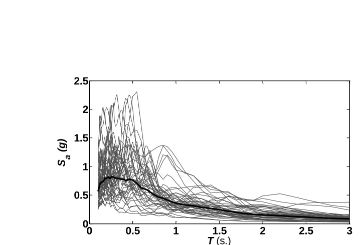
stiff soil and do not exhibit pulse-type near-fault characteristics. Fig. 2 plots the 5%
acceleration response spectra of the ground motions along with their geometric mean
spectrum. The ground motions were not scaled, but instead the strength fy of the system
was scaled to produce specific values of the Rμratio according to Eq. (4).
2.4 Response quantities
The main response quantities of interest are (1) the maximum (peak) displacement
m
u ; (2) the residual displacementur; and (3) the maximum (peak) total acceleration at,m.
The peak displacement and total acceleration are obtained as the maximum of the
absolute values of their time histories while residual displacement is obtained as the
absolute of the last value of the displacement time history.
The Newmark average acceleration method along with Newton-Raphson
iterations [6] was used to integrate the nonlinear equation of motion. The integration time
step was selected equal to 0.0005 s. since it has been shown that a particularly small
integration time step is needed to accurately predict accelerations [38, 39]. Smaller time
steps led to practically same response results. Each dynamic analysis was executed well
beyond the actual earthquake time to allow for damped free vibration decay and correct
This work first investigates the effect of the strength ratio Rμ on the peak response
of 5% damped systems. Then, the effect of supplemental damping on the peak response
quantity, x, is evaluated by presenting the ratio x(T,Rμ,ξ=ξt)/x(T,Rμ,ξ=5%). Finally, a
direct comparison of the peak response of highly damped BEP and SC systems is also
provided.
Structural response shows significant scatter due to ground motion variability and
hence, a statistical evaluation is used to identify trends. Assuming that the response to a
set of ground motions follows the lognormal distribution, the geometric mean (or referred
to herein as the median) of the response quantity x (or the ratio of x) is used to represent
the central tendency of the response.
3. Nonlinear seismic response results
3.1 Effect of strength ratio on 5% damped systems
The peak total acceleration, at,m, and peak displacement, um, of 5% damped BEP and SC systems are calculated and normalized with respect to the corresponding peak
responses of the elastic system (Rμ=1) having the same period of vibration. The residual
displacement of BEP systems is also calculated and normalized with respect to the peak
displacement of the elastic system. The median of the normalized responses to the ground
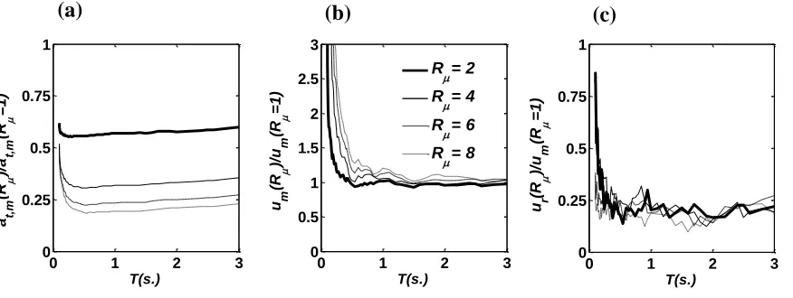
motion set is calculated and shown in Figs. 3 and 4.
Fig. 3(a) shows that the normalized at,mof BEP systems can be effectively decreased by increasing Rμ. This effect is more significant for systems with low Rμ
values. For example, increasing Rμ of systems with T=1 s. from 2 to 4 (50% decrease in
from 4 to 8 (50% decrease in strength for a given ground motion) results in 39% decrease
inat,m. For a given Rμ and for T>0.3 s., the normalized at,m is approximately constant and
period independent. For very short period systems, at,mincreases as period decreases and eventually approaches the peak ground acceleration as T tends to zero [6].
Fig. 3(b) shows that the normalized um of BEP systems tends toward infinity as T
decreases and toward unity for T longer than 0.5 s. regardless of the Rμvalue. The results
confirm the well-known equal displacement rule (i.e., um(Rμ)=um(Rμ=1)) for long period
systems as well as the strong dependence of um on the strength ratio for short period systems [6].
Fig. 3(c) shows that the normalized ur of BEP systems is approximately constant
regardless of the Rμ value in the long period region and increases in the short period
region. These results are consistent with the findings by previous researchers for systems
with nonzero positive post-yielding stiffness [10].
Fig. 4 displays the influence of the strength ratio on the median of the normalized
peak response of 5% damped SC systems with βΕ=25% or 50%. Figs. 4 (a) and (c) show
that the normalized at,m of SC systems with βΕ=25% exhibit almost identical trends with
those of SC systems with βΕ=50%. A close examination of Fig. 4(b) reveals that the
normalized um of SC systems with βΕ=25% and Rμ≥4 is above unity over the entire
period region. This indicates that the equal-displacement rule would be unconservative
for these systems. A comparison of Figs. 4(b), 4(d) and 3(b) indicates that SC systems
of previous works [26-27]. The urof self-centering systems was not studied since SC
systems oscillate around the origin and result in zero residual displacement.
3.2 Highly damped bilinear elastoplastic systems
In order to investigate the influence of supplemental viscous damping on the peak
response of BEP systems, the peak responses of highly damped BEP systems are
normalized with respect to the corresponding peak responses of 5% damped BEP systems
having the same period of vibration and Rμ factor. The median of the normalized
responses to the ground motion set is calculated and presented in the following figures.
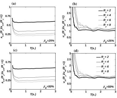
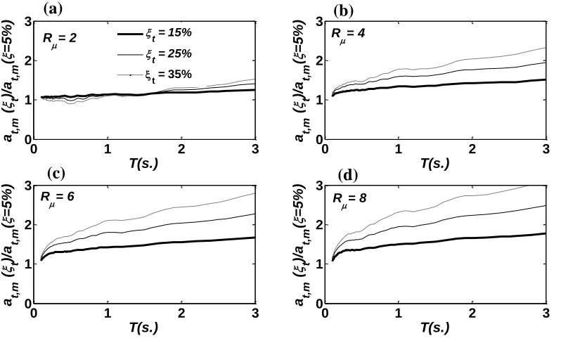
Fig. 5 shows the normalized at,m of highly damped BEP systems for different Rμ
and ξt values. Fig. 5(a) shows that the normalized at,mof BEP systems with Rμ=2 is
almost unity over the entire period region regardless of the ξt value. An increase in ξt
tends to slightly decrease the normalized at,m for T <1.0 s., while this trend is reversed for T>1.0 s. The results indicate that added damping has no influence on at,mof systems
with low strength ratio (Rμ=2). This can be explained since highly damped systems with
Rμ=2 remain mildly inelastic (i.e., they have approximate Rμ,d values equal to 1.48, 1.14
and 1.02 for ξt = 15%, 25% and 35%, respectively; refer to Section 2.2) and therefore, the
peaks of the damping force fD are generally out of phase with the peaks of the restoring
force fR (see Eq. (3)). Figs. 5 (b)-(d) show that the normalized at,mof BEP systems with Rμ≥4 increases as ξt increases, with the exception of very short period systems. This
increase becomes more pronounced for systems with longer period and larger Rμ. For
T=1.0 s.; 90% for Rμ=4 and T=3.0 s.; 95% for Rμ=8 and T=1.0 s.; and, 150% for Rμ=8
and T=3.0 s. These increases are not surprising since the behavior of highly damped
systems with Rμ≥4 is fully inelastic and the phase difference between the peaks of the
damping force fD and the peaks of the restoring fR is small (see Eq.(3)). The at,m of very
short period systems approaches the peak ground acceleration as T tends to zero and is
not influenced by added damping.
Fig. 6 displays the normalized umof highly damped BEP systems for different Rμ
and ξt values. Fig. 6 reveals that the normalized um is always less than unity, decreases
with increasing damping, and is relatively constant for almost the entire period region.
The umreductions due to added damping are more pronounced for short period systems.
A comparison between Figs. 6 (a) and (d) reveals that for a given ξt, the median of the
normalized um of systems with low Rμ has similar values with the normalized um of
systems with high Rμ. This indicates that the effect of added damping to reduce um is
independent of the strength ratio of the system and further suggests that the damping
modification factor derived from linear elastic systems (e.g., B factor in FEMA [16]) can
be also used for estimating the peak displacement response of highly damped inelastic
systems.
Fig.7 shows the normalized urof BEP systems for different Rμ and ξt values. Fig.
7(a) shows that, except for short period systems, BEP systems with Rμ=2 and ξt ≥ 25%
have zero normalized ur(i.e., zero residual displacement) since they remain nearly elastic
(i.e., the approximate Rμ,d factors of these systems are less than 1.1). Figs. 7 (b)-(d) show
normalized urfor different ξt becomes less obvious for systems with large Rμ values.
Therefore, adding damping is less effective in reducing residual displacements of systems
with high strength ratio. Interestingly, this work uncovers that added damping may
increase ur for particular systems (e.g., the normalized ur is larger than unity for Rμ=4,
T=1.8 s. and ξt=15%).
3.3 Highly damped self-centering systems
Fig. 8 displays the median of the at,m of highly damped SC systems normalized with respect to the at,mof 5% damped SC systems for different Rμ and ξt values. In
comparison with Fig. 5, the trend of the normalized at,m for highly damped SC systems is
very similar to that observed in highly damped BEP systems. The similarity in the trends
is also observed between SC systems with different E values. As a result, conclusions
similar to those for BEP systems can be made for SC systems.
Fig. 9 shows the median of the um of highly damped SC systems normalized with respect to the um of the 5% damped SC system for different Rμ and ξt values. Compared
to the highly damped BEP systems shown in Fig. 6, similar trends in the relationship
between um and added damping are observed. As a result, conclusions similar to those for BEP systems can be made for SC systems. Additionally, it is shown that βΕ has little
influence on the relation between added damping andum.
Figs. 6 to 9 show that added damping has similar effects on the peak responses of
BEP systems and SC systems of the same period and strength ratio. However, a better
insight into the seismic behavior of these systems can be gained by a direct comparison of
their peak responses. The median of the ratios of the peak responses of highly damped SC
systems to the corresponding responses of highly damped BEP systems having the same
T, ξt, and Rμ has been calculated and presented in the following figures.
Fig. 10 displays the median of the ratio of um of highly damped SC systems with E =50% to the umof highly damped BEP systems for different Rμ and ξtvalues. The ratio
is typically larger than unity for Rμ≥4 and T<1.0 s., and, approaches unity as T increases.
Therefore, BEP and SC systems have comparable displacements for T>1.0 s. Increasing
damping slightly decreases the ratio of umbetween SC and BEP systems. This indicates
that added damping is slightly more effective in reducing the peak displacements of SC
systems rather than the peak displacements of BEP systems. Fig. 10(a) shows that SC and
BEP systems experience identical displacements for all values of damping when Rμ=2.
Highly damped systems with Rμ=2 remain mildly inelastic and therefore, the hysteretic
behavior (SC or BEP) has no effect on peak displacement response.
Fig. 11 displays the median of the ratio of at,mof highly damped SC systems with
E =50% to the at,mof highly damped BEP systems for different Rμ and ξt values. The
ratio is larger than unity in the short period region and slightly larger than unity in the
long period region, indicating that at,mof highly damped SC systems are larger than that
of highly damped BEP systems. Increasing damping decreases the ratio of at,mbetween
accelerations of SC systems rather than those of BEP systems. Fig. 11(a) shows that SC
and BEP systems experience identical peak total accelerations for all values of damping
when Rμ=2.
4. Design for high-seismic structural and non-structural performance
This section demonstrates how the results presented in Section 3 can be
considered when designing highly damped structures to achieve structural and
non-structural damage reductions. The discussion is based on the equivalent nonlinear SDOF
representations of four 2-story conventional steel MRFs presented in Karavasilis et al.
[22-23].
Table 2 provides information about the four steel MRFs. MRF100 is a
conventional steel MRF that satisfies the strength and drift criteria of the IBC 2003 [34].
MRF75, MRF50 and MRF25 are MRFs designed for base shears equal to 0.75Vd, 0.50Vd
and 0.25Vd, where Vd is the design base shear of the MRF100. Table 2 includes the
fundamental period of vibration T1, the base shear coefficient V/W (V is the base shear
strength from pushover analysis and W is the seismic weight), the design spectral
acceleration Sa at period T1, the strength ratio Rμ, the peak displacement um, the residual
displacement ur and the peak total acceleration at,m. The spectral acceleration, Sa, was
obtained from the 5% damped design response spectrum with parameters SDS=1.0g,
SD1=0.6g, T0=0.12 s. and Ts=0.6 s. [34]. The Rμfactor was determined as
W V g
S V
mS
R a a
The peak displacement was calculated on the basis of the equal displacement rule, i.e.,
um=(T/2π)2Sa. With the Rμ and um known, the ur was obtained from Fig. 3(c), while
m t
a, was obtained from Fig. 3(a) based on the fairly accurate assumption that the peak total acceleration for Rμ=1 is equal to the spectral acceleration for 5% damping, i.e.,
m t
a, (Rμ=1,ξ=5%)Sa(ξ=5%) [6].
Linear viscous dampers are installed in the MRFs to achieve 25% total damping
ratio at the fundamental period of vibration. With the total damping ratio known, the peak
total acceleration, peak displacement and residual displacement of the highly damped
frames (denoted as DMRF100, 75, 50 and 25) are determined from Figs. 5, 6, and 7,
respectively. Table 3 provides the peak displacement, residual displacement and peak
total acceleration of the highly damped MRFs normalized with the corresponding
response quantities of the conventional MRF100 without dampers.
DMRF100 provides the highest displacement reduction, and also eliminates
residual displacement. However, DMRF100 experiences peak total accelerations similar
to those of the MRF100. DMRF25 provides the highest total acceleration reduction but
experiences displacements similar to those of MRF100. DMRF75 and DMRF50 are
design cases with the potential to achieve a simultaneous reduction of structural (drift,
residual drift) and non-structural (drift, total acceleration) damage. These design cases
illustrate that structural and non-structural performances of buildings with rate-dependent
dampers significantly depend on the mechanical properties (strength ratio and period) of
the initial frame design. In addition, the results presented in Figs. 3-11 along with the
simple design cases of this section shed more light on important outcomes of previous
frames with different strengths, periods of vibration and total damping ratios (e.g., [17,
20-23]).
5. Summary and conclusions
The purpose of this paper was to address various research needs relevant to the
structural and non-structural seismic behavior of conventional and self-centering systems
equipped with viscous dampers. For this purpose, a parametric study on the seismic
response of highly damped single-degree-of-freedom systems with self-centering (SC)
flag-shaped or bilinear elastoplastic (BEP) hysteresis was conducted. Statistical response
results were used to evaluate the effects of supplemental viscous damping , strength ratio
Rμ defined with reference to the 5% damped spectrum, and, period of vibration on
seismic peak displacements, residual displacements and peak total accelerations.
The effect of the strength ratio on the peak responses of 5% damped SC and BEP
systems was investigated. The results confirmed findings of previous works relevant to
peak displacements and residual displacements. In addition, the following conclusions
were drawn:
1. Peak total accelerations can be effectively reduced by increasing the strength ratio
(decreasing the strength for a given ground motion) of yielding systems. This effect is
practically independent of the period of vibration except for very short period systems.
2. Peak total acceleration reduction due to strength ratio increase is more significant for
systems with initial low values of the strength ratio. For example, increasing Rμ of
systems with T=1 s. from 2 to 4 and from 4 to 8 (50% decrease in strength for a given
The effect of supplemental viscous damping on the peak response of SC and BEP
systems was evaluated. The results confirmed findings of previous works relevant to peak
displacements. In addition, the following conclusions were drawn:
3. Adding damping to systems with low strength ratio (Rμ=2) does not influence peak
total accelerations.
4. The peak total acceleration of systems with Rμ≥4 increases when added damping
increases.
5. The increase in total acceleration due to added damping becomes more pronounced for
systems with a longer period and larger Rμ values. For example, by increasing the
viscous damping ratio from 5% to 25%, peak total acceleration increases by 60% for
Rμ=4 and T=1.0 s.; 90% for Rμ=4 and T=3.0 s.; 95% for Rμ=8 and T=1.0 s.; and,
150% for Rμ=8 and T=3.0 s.
6. The relative hysteretic energy dissipation ratio has no influence on the relation
between added damping and peak displacement of SC systems.
7. In general, added damping decreases residual displacements of BEP systems. This
effect is less pronounced for systems with high strength ratio values.
8. In some instances, added damping may result in increased residual displacements.
A direct comparison between the peak responses of highly damped BEP and highly
damped SC systems was also conducted and the following conclusions were drawn:
9. The two systems experience identical peak total accelerations for all values of
damping when Rμ=2.
10. Added damping affects more the peak total accelerations of SC systems rather than
11. Added damping is slightly more effective in reducing the peak displacements of SC
systems rather than the peak displacements of BEP systems.
Simple design cases of a conventional 2-story steel MRF and 2-story steel MRFs
equipped with linear viscous dampers providing a total damping ratio equal to 25% at the
fundamental period of vibration were presented. The results of the parametric study on
single-degree-of-freedom systems were used to evaluate the peak responses of the steel
MRFs and the following conclusions were drawn:
12. The structural and non-structural performance of buildings with rate-dependent
dampers significantly depends on the mechanical properties (strength ratio and
period of vibration) of the initial frame design.
13. Highly damped steel MRFs with strength within the range of 50 to 75% of the
strength of conventional steel MRFs are able to simultaneously reduce peak drifts,
residual drifts and peak total accelerations.
Interpretation of the aforementioned conclusions needs to be made on the basis of
the assumptions for the structural models and ground motions used in this paper.
Acknowledgements
The authors acknowledge the anonymous reviewers whose comments significantly
improved this paper.
References
[1] FEMA 445. Next-Generation Performance-based Seismic Design Guidelines.
[2] ATC-69. Reducing the Risks of Non-structural Earthquake Damage. Redwood, CA.
[3] Dolce M., and Manfredi G. Research Needs in Earthquake Engineering Highlighted
by the 2009 L’Aquila Earthquake. The state of Earthquake Engineering Research in
Italy: the ReLUIS-DPC 2005-2008 Project. 2009.
[4] CEN Eurocode 8. Design of Structures for Earthquake Resistance. Part1: General
Rules, Seismic Actions and Rules for Buildings. European Committee for
Standardization. 2004.
[5] Ramirez S. M., and Miranda E. Building-specific Loss Estimation Methods &
Tools for Simplified Performance-based Earthquake Engineering, John A. Blume
Earthquake Engineering Research Center, Rep. No. 171, Stanford University, CA.
2009.
[6] Chopra A. K. Dynamics of Structures. Theory and Applications to Earthquake
Engineering. 2nd Edition. Prentice Hall. 2001.
[7] McCormick J., Aburano H., Ikenaga M., Nakashima M. Permissible residual
deformation levels for building structures considering both safety and human
elements. 14th Conference on Earthquake Engineering. Beijing, China, 12-17
October, 2008.
[8] MacRae G.A., Kawashima K. Post-earthquake residual displacements of bilinear
oscillators. Earthquake Engineering and Structural Dynamics 1997; 26:701-716.
[9] Christopoulos C., Pampanin S., Priestley M.J.N. Performance-based seismic
response of frame structures including residual deformations. Part I: Single-degree
of freedom systems. Journal of Earthquake Engineering 2003; 7(1):97-118.
structures. Earthquake Engineering and Structural Dynamics 2006; 35:315-336.
[11] Pampanin S., Christopoulos C., Priestley M.J.N. Performance-based seismic
response of frame structures including residual deformations. Part II: Multi-degree
of freedom systems. Journal of Earthquake Engineering 2003; 7(1):119-147.
[12] Pettinga J.D., Priestley M.J.N, Pampanin S., Christopoulos C. The role of inelastic
torsion in the determination of residual deformations. Journal of Earthquake
Engineering 2007; 11:133-157.
[13] Symans M. D., Charney F. A., Whittaker A. S., Constantinou M. C., Kircher C. A.,
Johnson M. W., and McNamara R. J. Energy Dissipation Systems for Seismic
Applications: Current Practice and Recent Developments. Journal of Structural
Engineering-ASCE 2008; 134(1): 3-21.
[14] Lin W.-H., and Chopra A. K. Earthquake Response of Elastic
Single-Degree-of-Freedom Systems with Nonlinear Viscoelastic Dampers. Journal of Engineering
Mechanics-ASCE 2003; 129(6): 597-606.
[15] Ramirez O. M., Constantinou M. C., Whittaker A. S., Kircher C.A., and
Chrysostomou C. Z. Elastic and Inelastic Seismic Response of Buildings with
Damping Systems. Earthquake Spectra 2002; 18(3): 531-547.
[16] FEMA 450. NEHRP Recommended Provisions for Seismic Regulations for New
Buildings and Other Structures: Part 1—Provisions. Federal Emergency
Management Agency, Washington, D.C., 2003.
[17] Pavlou E., and Constantinou M. C. Response of Nonstructural Components in
Structures with Damping Systems. Journal of Structural Engineering (ASCE) 2006;
[18] Lee K. S., Ricles J., and Sause R. Performance Based Seismic Design of Steel
MRFs with Elastomeric Dampers. Journal of Structural Engineering-ASCE 2009;
135(5): 489-498.
[19] Vargas R., and Bruneau M. Effect of Supplemental Viscous Damping on the
Seismic Response of Structural Systems with Metallic Dampers. Journal of
Structural Engineering (ASCE) 2007; 133(10): 1434-1444.
[20] Wanitkorkul A., and Filiatrault A. Influence of Passive Supplemental Damping
Systems on Structural and Nonstructural Seismic Fragilities of a Steel Building.
Engineering Structures 2008; 30(3): 675-682.
[21] Occhiuzzi A. Additional Viscous Dampers for Civil Structures: Analysis of Design
Methods Based on Effective Evaluation of Modal Damping Rations. Engineering
Structures 2009; 31(5): 1093-1101.
[22] Karavasilis T.L., Sause R., and Ricles J. M. Seismic Design and Performance of
Steel MRFs with Elastomeric Dampers. Earthquake Engineering and Structural
Dynamics 2011; under review.
[23] Karavasilis T. L., Ricles J. M., Sause R., and Chen C. Experimental evaluation of
the seismic performance of steel MRFs with compressed elastomer dampers using
large-scale real-time hybrid simulation. Engineering Structures 2011; in press.
[24] Garlock M., Sause R., and Ricles J. M. Behavior and Design of Post-tensioned
Steel Frame Systems. Journal of Structural Engineering (ASCE) 2007; 133(3)
:389-399.
[25] Tremblay R., Lacerte M., and Christopoulos C. Seismic Response of Multistory
Engineering (ASCE) 2008; 134(1): 108-120.
[26] Christopoulos C., Filiatrault A., and Folz B. Seismic Response of Self-centering
Hysteretic SDOF Systems. Earthquake Engineering and Structural Dynamics 2002;
31(5): 1131-1150.
[27] Seo C.-Y., and Sause R. Ductility Demands on Self-centering Systems under
Earthquake Loading. ACI Structural Journal 2005; 102(2):275-285.
[28] Kam W.-Y., Pampanin S., Palermo A., Carr A.J. Earthquake Engineering and
Structural Dynamics 2010; 39(10):1083-1108.
[29] Viti S., Cimellaro G. P., and Reinhorn A. M. Retrofit of a Hospital through Strength
Reduction and Enhanced Damping. Smart Structures and Systems 2006; 2(4):
339-355.
[30] Roh H., Reinhorn A. M. Modeling and Seismic Response of Structures with
Concrete Rocking Columns and Viscous Dampers. Engineering Structures 2010;
32(8): 2096-2107.
[31] Lavan O., Cimellaro GP, and Reinhorn AM. Noniterative Optimization Procedure
for Seismic Weakening and Damping for Inelastic Structures. Journal of Structural
Engineering (ASCE) 2008; 134(10):1638-1648.
[32] Medina RA, Krawinkler H. Seismic demands for nondeteriorating frame structures
and their dependence on ground motions. Report No. 144, John A. Blume
Earthquake Engineering Research Center, Department of Civil and Environmental
Engineering, Stanford University, 2003.
[33] Ruiz-Garcia J., Miranda E. Evaluation of residual drift demands in regular
and Structural Dynamics 2006; 35:1609-1629.
[34] IBC 2003. International Code Council, Inc. Birmingham, AL, 2003.
[35] FEMA440. Improvement of nonlinear static seismic analysis procedures. ATC-55
project, Redwood City, California, 2008.
[36] Eatherton MR, Hajjar JF. Large-scale cyclic and hybrid simulation testing and
development of a controlled-rocking steel building system with replaceable fuses.
NSEL Report No. NSEL-025, Department of Civil and Environmental Engineering,
University of Illinois at Urbana-Champaign, 2010.
[37] ATC-63. Quantification of Building Seismic Performance Factors. FEMAP695.
Redwood City, California, 2008.
[38] Rodriguez M.A., Restrepo J.I., Blandon J.J. Shaking table tests of a four-story
miniature steel building –model validation. Earthquake Spectra 2006;
22(3):755-780.
[39] Wiebe L., Christopoulos C. Characterizing acceleration spikes due to stiffness
changes in nonlinear systems. Earthquake Engineering and Structural Dynamics
TABLES
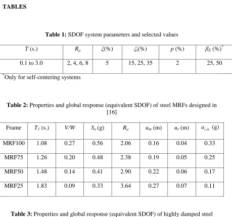
Table 1: SDOF system parameters and selected values
T (s.) Rμ ξ(%) ξt(%) p (%) βΕ (%)*
0.1 to 3.0 2, 4, 6, 8 5 15, 25, 35 2 25, 50
*
[image:31.612.85.544.66.495.2]Only for self-centering systems
Table 2: Properties and global response (equivalent SDOF) of steel MRFs designed in [16]
Frame T1 (s.) V/W Sa (g) Rμ um (m) ur (m) at,m (g)
MRF100 1.08 0.27 0.56 2.06 0.16 0.04 0.33
MRF75 1.26 0.20 0.48 2.38 0.19 0.05 0.25
MRF50 1.48 0.14 0.41 2.90 0.22 0.06 0.17
MRF25 1.83 0.09 0.33 3.64 0.27 0.07 0.11
Table 3: Properties and global response (equivalent SDOF) of highly damped steel MRFs having 25% damping ratio at the fundamental period of vibration
Frame um/um,MRF100 ur/ur,MRF100 at,m/at,m,MRF100
DMRF100 0.61 0.00 1.00
DMRF75 0.71 0.12 0.82
DMRF50 0.84 0.34 0.65
[image:31.612.87.528.308.457.2]FIGURES
[image:32.612.90.453.342.587.2]Figure 1: Hysteretic behavior of bilinear elastoplastic, BEP, (left) and self-centering, SC, flag-shaped (right) systems
Figure 2: Individual 5% damped acceleration response spectra (light lines) and geometric mean response spectrum (heavy line) of the ground motions considered in this study
ke
u fR
pke
fy
(1-2βΕ) fy
pke
ke
fy
u fR
0 0.5 1 1.5 2 2.5 3
0 0.5 1 1.5 2 2.5
T (s.)
S a
(
g
Figure 3: Influence of strength ratio Rμ on: (a) peak total accelerationat,m; (b) peak
displacement um; and (c) residual displacement ur of 5% damped bilinear elastoplastic
systems.
(a) (b) (c)
0 1 2 3
0 0.25 0.5 0.75 1 T(s.) a t, m (R )/ a t, m (R = 1 )
0 1 2 3
0 0.5 1 1.5 2 2.5 3 T(s.) u m (R )/ u m (R = 1 )
0 1 2 3
0 0.25 0.5 0.75 1 T(s.) u r (R )/ u m (R = 1 )
R = 2 R = 4 R = 6 R = 8
0 1 2 3
0 0.5 1 1.5 2 2.5 3 T(s.) u m (R )/ u m (R = 1)
R= 2
R= 4
R= 6
R= 8
0 1 2 3
0 0.5 1 1.5 2 2.5 3 T(s.) u m (R )/ u m (R = 1)
R= 2
R= 4
R= 6
R= 8
0 1 2 3
0 0.5 1 1.5 2 2.5 3 T(s.) a t, m (R )/ a t, m (R = 1)
R= 2
R= 4
R= 6
R= 8
0 1 2 3
Figure 4: Influence of strength ratio Rμ on peak total acceleration at,m and peak
displacement um of 5% damped self-centering systems with relative hysteretic energy
dissipation ratio βΕ equal to 25% and 50%.
0 1 2 3
0 0.25 0.5 0.75 1 T(s.) a t, m (R )/ a t, m (R = 1)
0 1 2 3
0 0.5 1 1.5 2 2.5 3 T(s.) u m (R )/ u m (R = 1)
R = 2 R = 4 R = 6 R = 8
E=25% E=25%
0 1 2 3
0 0.25 0.5 0.75 1 T(s.) a t, m (R )/ a t, m (R = 1)
0 1 2 3
0 0.5 1 1.5 2 2.5 3 T(s.) u m (R )/ u m (R = 1)
R = 2 R = 4 R = 6 R = 8
E=50% E=50%
(a) (b)
(c) (d)
0 1 2 3
0 0.5 1 1.5 2 2.5 3 T(s.) u m (R )/ u m (R = 1)
R= 2
R= 4
R= 6
R= 8
0 1 2 3
0 0.5 1 1.5 2 2.5 3 T(s.) u m (R )/ u m (R = 1)
R= 2
R= 4
R= 6
R= 8
0 1 2 3
0 0.5 1 1.5 2 2.5 3 T(s.) a t, m (R )/ a t, m (R = 1)
R= 2
R= 4
R= 6
R= 8
0 1 2 3
0 0.5 1 1.5 2 2.5 3 T(s.) a t, m (R )/ a t, m (R = 1)
R= 2
R= 4
R= 6
R= 8
0 1 2 3
0 0.5 1 1.5 2 2.5 3 T(s.) u m (R )/ u m (R = 1)
R= 2
R= 4
R= 6
R= 8
0 1 2 3
0 0.5 1 1.5 2 2.5 3 T(s.) u m (R )/ u m (R = 1)
R= 2
R= 4
R= 6
[image:34.612.111.492.107.425.2]0 1 2 3 0 1 2 3 T(s.) a t, m ( t )/ a t, m ( =
5%) R=2 t = 15%
t = 25%
t = 35%
0 1 2 3
0 1 2 3 R=4 T(s.) a t, m ( t )/ a t, m ( = 5%)
0 1 2 3
0 1 2 3 R=6 T(s.) a t, m ( t )/ a t, m ( = 5%)
0 1 2 3
0 1 2 3 R=8 T(s.) a t, m ( t )/ a t, m ( = 5%)
(a) (b)
(c) (d)
0 1 2 3
0 0.5 1 1.5 2 2.5 3 T(s.) u m (R )/ u m (R = 1)
R= 2
R= 4
R= 6
R= 8
0 1 2 3
0 0.5 1 1.5 2 2.5 3 T(s.) u m (R )/ u m (R = 1)
R= 2
R= 4
R= 6
R= 8
0 1 2 3
0 0.5 1 1.5 2 2.5 T(s.) u m (R )/ u m (R = 1)
R= 2
R= 4
R= 6
R= 8
0 1 2 3
0 0.5 1 1.5 2 2.5 3 T(s.) u m (R )/ u m (R = 1)
R= 2
R= 4
R= 6
R= 8
Figure 5: Influence of total viscous damping ratio ξt on peak total acceleration at,mof
[image:35.612.108.507.82.326.2]