Face Detector with Oriented Multiple Templates
Yea-Shuan Huang Wei-Cheng Liu
Abstract—This paper proposes a novel face detection
algorithm which extracts a local image structure (LIS) feature and adopts a boosting approach to construct a cascaded face detector. Due to the locality of LIS, the extracted feature is not only robust to lighting variation but also is invariant to small degrees of rotation. With this robust property a multiple-template cascaded detection algorithm has been developed which can avoid rotating the image and also keep the ability to detect slanted faces. Because the multiple templates are constructed in the initialization stage, the proposed face detector can be executed rapidly. Experiments on the BioID face database have shown the efficiency of this method.
Index Terms—Object Detection, Feature Extraction,
Classifier, Local Image Structure
I. INTRODUCTION
Due to the fast advancement of the computer-vision technology and the common usage of cameras (either still or mobile) installed in both our surrounding environment and electronic appliances, many vision-based applications such as video surveillance, man-machine interface, biometrics, and interactive game have been actively developed. Among these applications, face detection is a very essential preprocessing task that has attracted a lot of research attentions. Face detection locates the face candidates appeared in an image so that there are the right targets to perform further processing such as tracking and recognition. So far, many face detection algorithms [1, 2, 3, 4] have been proposed in the past decades. Among them, the boosting-based approaches in general have achieved the best performance on both detection accuracy and processing speed. Therefore, boosting-based face detectors have become the main research stream and indeed they can achieve a practical performance with a fast processor. But, almost all methods are still too slow to applications that use either a low-level processor for a single channel video signal or a high-level processor for multiple channel video signals. Therefore, it is crucial to further speedup the face detection process.
In general, a boosting-based face detector adopts a fixed size face template and is a multi-stage face filter. Each stage uses one or a few features to filter out the non-face regions. Only passing all stages successfully, a region is regarded as a face region. A processed image should be both scaled and rotated several times accordingly so that different orientations and sizes of faces can be detected. Unfortunately,
rotation of the whole image is quite time-consuming. Also, for each rotated image, it is necessary to re-compute the image feature. Therefore, the current detectors tend to be slow. If a method can avoid the operation of image rotation and still keep the detection ability of rotated faces, it will certainly execute more efficiently. To achieve this goal, one possible way is to extract a rotation-invariant face feature. However, it is very difficult to design such an ideal feature which needs to satisfy two conditions (rotation invariance and good discrimination between face and non-face) at the same time. Alternatively, one may implement a feature which value is just computed once from the original image but the corresponding feature values of the rotated image can be derived directly from the already computed feature. The main contribution of this paper is to provide one such feature and to design an appropriate mean so that face detection can be executed fast.
In this paper, we propose a novel face detection algorithm which avoids the image rotation operation for any rotation angles between ±22.5o. Section 2 describes the feature extraction method and shows its robustness to the lighting variation. Section 3 describes the used boosting algorithm to construct a face detector with a single template. Section 4 propose an improve face detector by avoiding rotating images with multiple templates. Section 5 designs a fast multi-template cascaded face detector which has no image rotation operations. Section 6 shows the experimental results on the famous BioID face database, and finally Section 7 concludes this paper.
II. FEATURE EXTRACTION BY LOCAL IMAGE STRUCTURE Let x be an image pixel, I(x), R(x) and L(x) be individually the image intensity, the reflectance vector and the
illumination vector of x. From the image formation optics, it exists I(x) = R(x).L(x). For another image pixel y, it becomes I(y) = R(y).L(y). Suppose pixels x and y are neighbors, then L(x) and L(y) are assumed to be very similar or even the same. So
( ) ( ) ( ) ( )
I x R x
I y ≈R y . (2)
This equation shows that the ratio of two neighboring pixels is almost independent of illumination vector, and it approximately keeps constant if only the background illumination changes and all other factors remain unchanged. However, besides illumination there are other factors (such as surface normal and noises) which can slightly affect the image intensity. Therefore, it is not proper to directly take the image ratio as features. Instead the contrast relationship (larger than or not larger than) is a better and more stable feature description in representing the relation among image pixels in the neighborhood. For any two pixels x and y, a contrast relationship is defined as
Manuscript received Januarary 7, 2008. This work was supported by the Ministry of Economic Affairs, R.O.C. under the project “Construction of Vision-Based Intelligent Environment (VBIE)”, the project code is
96-EC-17-A-02-S1-032.
⎩ ⎨ ⎧ ≥ = otherwise. 1, ; if 0, )
(I(x), I(y) I(x) I(y)
ζ (3)
The relationship obtains a value 0 if pixel x is not darker than pixel y, otherwise it obtains a value 1. Let Φ(x) = {P0, P1, …, PN-1} be an N-element set and each element correspond to a chosen neighboring pixel of x. This set Φ(x) is called the interestedly selected pixel set, which specifies how many and what pixels are chosen to derive the local image structure. It is not difficult to realize that by integrating a set of relationship ξ(I(x) ,I(pn)), among pixel
x and its selective neighboring pixels (P0,…,PN-1) a structure-like information can be constructed. In fact, the structure-like information semantically represents one kind of image texture information. With pixel relationships, the local image structure
1 -1
≤n≤N
( )x
Γ is designed as
∑
(4)Φ ∈ = × = Γ 1 ) ( , 0
i), (x)). p ( ( 2 ) ( n-x p i i i I I x ζ
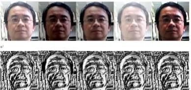
Figure 1 is an example of Φ(x) where the pixels marked I are the selected interested neighbor pixels. Practically, Φ(x) can be either assigned manually or determined by experiments. Figure 2 shows the adopted Φ(x) in this paper which uses only 8 nearest neighbors of x to construct its local structure. Such a 3×3 Φ(x) is also called the Local Binary Pattern (LBP). Obviously, with this configuration the corresponding Γ( )x has in total 256 possible values ranging from 0 to 255, and each value corresponds to one specific image structure. For example, when ( )Γ x is 0, it means that x is the brightest pixel among its 8 neighbors. For another example, when Γ( )x is 7, it means that among its 8 neighbors only P0, P1 and P2 are darker than x. This structure representation is very robust to many kinds of variations, especially the illumination variation. In Figure 3, an illustrative example is shown. The local image structures of 5 different-illumination images are visualized as index images where the structure index determines the pixel intensity. The 4 right images in the first row of Figure 3 are generated from the first image of the same row by using an image processing software with the following parameters: light value −75, contrast value −50, gamma value 2.0, and gamma value 0.4, respectively. It reveals that the designed image structure is fairly robust to the illumination variation.
III. CONSTRUCTION OF CASCADED FACE DETECTOR The face detector analyzes image patches W of size 15×15 pixels. The whole classification procedure consists of a sequence of stage tests performed on the analyzed patch. For each test, the patch may be rejected as background or be accepted as a possible face region for further tests. Only passing all the stage tests, a patch is considered to be a face candidate. Let be the jth stage test which classifies the current patch with one or a few positions of the local image structure (LIS) of this patch. Figure 4 shows a constructed face detector of which the LIS of both positions (3, 5) and (4, 1) are tested in the first stage, and the final stage test takes the LIS of 128 positions. Each test consists of a threshold, and when the summation of the outputs of weak classifiers is larger than its threshold, the processed
patch is considered to be background and is rejected for further test. The positions of LIS and their corresponding thresholds are obtained from a proposed boosting algorithm as described below:
)
(
H
jΓ
Step 1: Given Nf face training images and Nnf non-face training images of which each image is normalized to be 15×15 pixels.
Step 2: Compute the LIS features of all face and non-face images. Let and be the generated LIS of the face and non-face images, respectively, where m = 1,…,Nf and n = 1,…,Nnf, and is the LIS value of position p of the mth face image, where p belongs to the total position set A={0,…,224}. f m
Γ
nf nΓ
(p)
f mΓ
Step 3: Initialization. Let the iteration index t=1, =0.5/Nf, =0.5/Nnf, the set of the selective pixel positions S =Φ an empty set, where
and are individually the initial weight of the mth face image and the nth non-face image at the first iteration.
) (
1 m
Df ( )
1 n Dnf
) (
1 m
Df ( )
1 n Dnf
Step 4: Generate look-up tables of the total corresponding
weights and of the face
and non-face images for each position p∈A and structure γ∈ {0,…,255}
)
,
(
p
γ
f t
g
g
tnf(
p
,
γ
)
(
,
)
(
)
(
(
)
)
, ,γ
γ
γ=
Γ
=
∑
p
p
p f m m f t ft
D
m
F
g
and)
)
(
(
)
(
)
,
(
, ,γ
γ
γ=
Γ
=
∑
p
p
p nf n n nf t nft
D
n
F
g
where F() is the indicator function that takes 1 if the argument is true and 0 otherwise.
Step 5: Calculate error δt of position p from the computed lookup table: . A , )} , ( ), , ( { min )
(p =
∑
p p ∀p∈γ γ γ δ nf t f t
t g g
Step 6: Select the best position pt at iteration t and update the selected position location set S:
}
∪
=
=
∈ t A{p
S
S
)
(
min
arg
p
p
p t tδ
,Step 7: Generate another lookup table for the weak classifier at iteration t and position pt:
. 255 , 0 , else 1 ) , ( ) , ( if 0 )
( = K
⎩ ⎨
⎧ >
= γ γ γ
γ t nf t t f t t g g
w p p
,
Step 8: Obtain a value αt from the error at iteration t:
⎟⎟ ⎠ ⎞ ⎜⎜ ⎝ ⎛ − = t t t δ δ α ln 1
2
1 .
. 255 , , 0 ), ( )
(
γ
=α
twtγ
γ
= Kh
t
p
Step 10: Update the distributions:
,
⎩ ⎨
⎧ Γ =
× = − else 0 )) ( ( if ) ( ) ( t t e w e m D m A f m t f t α α p , ⎩ ⎨
⎧ Γ =
× = − else 1 )) ( ( if ) ( ) ( t t e w e n D n B nf m t nf t α α p
1 1 ) ( ) ( + + = t f t Z m A m D
,
1 1 ) ( ) ( + + = t nf t Z m B m D
where zt+1 is a normalization factor determined by the following equation:
) ( ) (
1 m m n n
t
z+ =∑
A
+∑B
.Step 11: Increase the iteration index t with 1. If t is smaller than a pre-specified stopping value T, go to Step 4. Otherwise, go to Step 12.
Step 12: Obtain the final strong classifier at ith stage based on the final face model:
.
S ( ( )) )( ∑
∈ Γ
= Γ
p hp p
i H
Here, symbol A denotes the total pixel position, i.e., A={0,…,224}, symbol t denote the iteration index,
γ
=
Γ
(p)
denotes that the local structure of pixel p is γ, and are individually the total weights of face samples and non-face samples with)
,
(
p
γ
f t
g
g
tnf(
p
,
γ
)
γ
=
Γ
(p)
atiteration t. In step 5, the individual error of
Γ
(p)
=
γ
is thesmaller value between and because
this smaller value corresponds to the possible error if a decision is made to decide whether a patch is face or non-face when only observing the information that the local structure of pixel P is γ (i.e.
)
,
(
p
γ
f t
g
g
tnf(
p
,
γ
)
γ
=
Γ
(p)
), and the total errorδ
t(
p
)
of position p is the summation of the individual errors ofγ
=
Γ
(p)
. For the t-th iteration, a position pt is chosen and is added into the selected position set S if it has the minimal error among the errors of all positions. Also, each structure γat position pt has a penalty value
h
pt(
γ
)
. Basically,h
pt(
γ
)
is determined by two factors derived from samples of
γ
=
Γ
(p)
. The first factor is whether the total population of non-face samples is larger than that of face samples or not as checked in step 7, and the second factor is the penalty is proportional to)
,
(
tnf t
γ
g
p
)
,
(
t t
γ
fg
p
t
α
which in fact is computed fromδ
t(
p
t)
in step 8. The first factor tells us when there are more samples belonging to non face than belonging to face, a penalty value can be practically assigned.On the contrary, when there are more samples belonging to face than belonging to non face, the penalty should be quite conservative and even be 0 as assigned in this algorithm. Because
α
tis computed fromδ
t(
p
)
and0
≤
δ
t(
p
)
≤
0.5
, the second factor in fact means that a largerδ
t(
p
t)
derives a smallerh
pt(
γ
)
and a smallerδ
t(
p
t)
derives a largerh
pt(
γ
)
. A largeδ
t(
p
t)
in fact denotes it is difficult to make a decision whether the current sample belongs to face or non face. By the proposed algorithm, a background patch will inherently obtain a large response value and therefore will be rejected in the early stage tests. But, a face patch will obtain a small response value and will pass all stage tests.IV. FACE DETECTION BY SINGLE TEMPLATE
From Section 3, a cascaded face detector is constructed. The positions pt and their corresponding penalties hpt(γ) are
optimally derived by an algorithm proposed in [5]. Suppose there are N positions (i.e. S={p1,…,pN}) are selected in total which are accordingly formed into M stages with threshold {h1,…,hM}. Due to the limited space, the formation of stages is not explained in this paper. Let Si denote the extra positions used in the i-th stage which are not used in the (i-1)-th stage , be the j-th position of Si and ni be the total number of positions in Si. Then and S=S1∪S2∪… ∪SM. In the first stage, n1 positions defined in S1 are used to compute the LIS of the current processed 15×15 patch W, and the computed LIS value of each position p becomes the index to retrieve its corresponding penalty value
i j p } p , , {p S i n i 1
i= L i
). ( ( p
p Γ
h
Therefore, the penalty value of the first stage is . )) ( ( ) ( 1 S 1 Γ =
∑
p∈ hp ΓpH If is larger than h1, W is
regarded to be a non-face pattern and is rejected for any further check. Otherwise, n2 positions defined in S2 will be used to calculate their penalties in stage 2 and the total penalty until stage 2 becomes
) ( 1 Γ H . )) ( ( ) ( ) ( 2 S 1
2 Γ =H Γ +
∑
p∈ hp Γp HAgain, if H2(Γ)is larger than h2, W is regarded as a non-face pattern and is rejected. Sequentially, the similar process can be performed for stage 3, stage 4,…, and stage M. Only passing all M stages successfully, a patch W is considered to be a face pattern.
In order to detect various sizes and orientations of face patterns, image transforms such as scaling and rotation should be performed on the processed image accordingly. Each image transform not only spends a lot of computation time but also needs to compute the LIS features of the transformed image. Therefore, the face detection becomes slow.
Tproposed = D2×[s + f + R×d] ...(the 1st resized image) neighboring pixels which are quite robust to image rotation.
For a 3×3 region, the LIS features of any rotation angle between +22.5o and -22.5o in fact is inherently the same to each other. Therefore, it is unnecessary to re-compute the LIS feature of each pixel if the image is rotated under ±22.5o. However, the chosen positions from a 15×15 template can be used to detect only the upright front face. For detecting a certain angle of rotated faces, instead of rotating the whole image, we rotate the temple and select the corresponding positions of the rotated template. In Figure 5, we use a 4×4 template to simplify the explanation. Suppose the origin of the template is at the left bottom, the 4 selected positions of the cascaded face detector are marked by a white-gray color and their positions are (0,2), (1,3), (2,1), and (3,0). In fact, each position is described by two values relative to the origin of which the first value is the horizontal offset and the second value is the vertical offset. Therefore, position (2,1) denotes the grid which is two-pixel right and one-pixel above to the origin of the template. For a -15o rotated template, the corresponding grid offsets to the origin are (1,2), (2,3), (2,0), and (3,-1) respectively as shown in Figure 4. With this realization, it is easy to derive different templates to detect different angles of rotated faces. For example, 7 templates are constructed for detecting faces under ±15o rotation as shown in Figure 6 and each template supervises a range of 5o rotated faces.
For making a formal analysis of the proposed method, some symbols are defined here. Let Q be the input image consisting of M×N pixels, s be the time of resizing Q with ratio D, r be the time of rotating Q, f be the time of computing the LIS of Q, and d be the time of detecting faces of Q. Suppose Q is resized in total R times, D is the resize ratio of each time, and the overall operation time of each resized image including image scaling, image rotation, and LIS computation is approximately proportional to the pixel number of the resized image. Since both the resize ratios of width and length are D which is smaller than 1.0, the first resized image has M×N×D2 pixels, the second resized image has M×N×D4 pixels, and the nth resized image has M×N×D2n pixels. Traditionally, a boosting approach uses only one template to detect all faces of different sizes and different rotations by continuously resizing and rotating image. Let Ttradition be the processing time of a traditional boosting method which resizes the original image n times, and for each resized image there are R times of both image rotations and LIS feature extractions. Therefore, to detect faces within ± 22.5o, T
tradition requires
+ …
+ D2(n-1)×[s+ f + R×d] ...(the nth resized image) = [s + f + R×d] [D2+….+D2(n-1)]
= [s + f + R×d]
∑
n=-1 1 i2i
D
By dividing Ttradition by Tproposed, the speedup ratio S becomes
d] R f [s
d)] f (r R [s T T S
proposed tradition
× + +
+ + × + = =
For an example of a 320*240 image, suppose s=1ms, r=3ms, f=2ms, d=3ms, D=0.9, n=8 and R=5. Then Ttradition is 82ms, Tproposed is 34ms, and S is about 2.4.
VI. EXPERIMENTS
In this section, we use the images in the BioID database, a well-known face database, to perform our experiments. BioID contains 1521 front–view gray level face images with a resolution of 384×286 pixels. The database features a large variety of illumination and face sizes, and the background of images is very complex. This database is believed to be more difficult than other commonly-used head-and-shoulder face database without complex background, e.g. the extended M2VTS database.
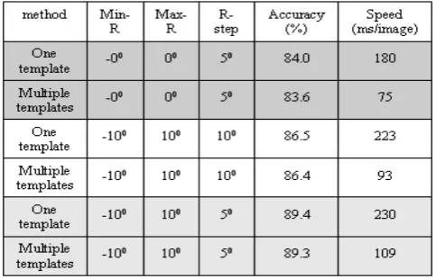
The essence of this paper is to propose a face detection method which adopts a multiple-template strategy so that the detection speed can be considerably improved. Therefore, we compare the face detection accuracies and speeds of two methods (single-template boosting and multiple-template boosting) on BioID, both methods use the LIS feature and the proposed boosting algorithm to train the cascaded detector. With the single template, images should be rotated several times in order to detect different slanted faces; however, with multiple templates no image rotation is required. In our experiments, different parameters are arranged to investigate the performance of the proposed algorithm. Table 1 shows the detection results where Min_R is the minimal rotation angle, Max_R is the maximal rotation angle, R_step is the increment angle of each rotation, and the image scaling ration D is set to 0.85. The experiments are performed on a PC with windows 2000/XP, Pentium IV 1.6 GHz CPU and 1G main memory. The experimental results clear show that the proposed algorithm can achieve a good face detection rate ( ≒ 90%) and the multiple-template strategy indeed considerably accelerate the detection speed.
Ttradition = D2×[s + R×(r+f+d)]…(the 1st resized image) + D4×[s + R×(r+f+d)...(the 2st resized image)
VII. CONCLUSION
This paper proposes a novel face detection algorithm which extracts a local image structure (LIS) feature and adopts a boosting approach to construct a cascaded face detector. Due to the locality of LIS, the extracted feature is not only robust to lighting variation but also is invariant to small degrees of rotation. With this robust property a multiple-template cascaded detector has been developed which can avoid rotating the image and also keep the ability to detect slanted faces. Because the multiple templates are constructed in the initialization stage, the proposed algorithm + …
+D2(n-1)×[s+R×(r+f+d)]...(the nth resized image) = [s + R×(r+f+d)] [D2+….+D2(n-1)]
= [s + R×(r+f+d)]
∑
n=-1 1 i2i
D
can be executed very fast. Experiments have shown the efficiency of this method.
Since LIS is invariant only under the rotation of ±22.5o, it is important to extend the proposed method so that a large rotated face can also be correctly detected. This will be our future research direction.
ACKNOWLEDGMENT
[image:5.595.330.525.51.143.2]This paper is the research result sponsored by the MOEA project “Construction of Vision-Based Intelligent Environment (VBIE)”, the project code is 96-EC-17-A-02-S1-032.
Figure 3: Images with different illumination are shown in the first row, and the corresponding images of derived local structures are shown in the second row.
REFERENCES
[1] K.K. Sung and T. Poggio, “Example-Based Learning for View-Based Human Face Detection”, in Proceedings IEEE Trans. On Pattern Analysis and Machine Intelligence, vol. 20(1), pp. 39-51, 1998.
[image:5.595.310.543.345.497.2][2] M.H. Yang, N. Ahuja and D. Kriegman, “Face Detection Using a Mixture of Factor Analyzers”, In Proceedings of IEEE International Conference on Image Processing, Vol. 3, pp. 612-616, 1999.
Figure 1: A cascaded face detector
[3] P. Viola and M. Jones, “Rapid Object Detection Using a Boosted Cascaded of Simple Features”, in Proceedings IEEE Conf. on Computer Vision and Pattern Recognition, vol. 1, pp. 511-518, 2001.
[4] Yea-Shuan Huang, Hao-ying Cheng, Po-Feng Cheng and Cheng-Yuan Tang, ” Face Detection with High Precision Based on Radial-Symmetry Transform and Eye-Pair Checking”, IEEE Conference on video and signal based surveillance, 2006.
[image:5.595.137.205.524.582.2][5] B. Frba and A. Ernst, "Face Detection with the Modified Census Transform", Proc. IEEE Int. Conf. on Automatic Face and Gesture Recognition (AFGR), Seoul, 2004, pp. 91-96.
Figure 5: Two 4×4 illustrated templates. (a) the template of 0o-rotated faces, and (b) the template of 15o-rotated faces.
Figure 1: One example of the interestedly selected pixel set Φ(X), where X denotes a being processed pixel and the pixels marked I denotes the selected interested neighbor pixels.
P3 P2 P1
P4 X P0
P5 P6 P7
Figure 2: One example of the interestedly selected pixel set Φ(X), where 8 neighbors of X, P0, P1, P2, P3, P4, P5, P6 and P7,
[image:5.595.316.545.577.731.2] [image:5.595.138.199.660.722.2]