Bit Error Rate of Orthogonal Frequency Division
Multipexing System
Umesha G. B.
Research Scholar
Department of ECE
SJCE Mysore
M. N. Shanmukha Swamy,
PhD
Supervisor
Department of ECE
SJCE Mysore
ABSTRACT
Bit Error rate of OFDM is carried out with the help of cyclic prefix and the length of a guard interval varies. The BER is low for the given system indicates that amount of data received at the receiver is equal to the data transmitted by transmitter. To achieve best communication guard interval is used between the subcarriers and effect of Inter Carrier Interference (ICI) can be reduced by maintain orthogonality between subcarriers. Different guard length is used over here to analyze distortion for the additive white Gaussian noise and Rayleigh fading channels and avoid Inter symbol Interference (ISI).
General Terms
Fast Fourier Transform, Inter Carrier Interference, Orthogonality, Inter Symbol Interference and Additive White Gaussian Noise.
Keywords
Orthogonal Frequency Multiplexing Division (OFDM), Guard Interval (GI), cyclic prefix and Quadrature Amplitude Modulation (QAM).
1.
INTRODUCTION
The nature of future wireless applications demands high data rates. OFDM is a special form of multicarrier where all the subcarriers are orthogonal to each other. It promises a high user data rate transmission capability at reasonable precisions. At high data rates, the channel distortion to the data is very significant and it is impossible to recover the transmitted data with a simple receiver. A complexity receiver design is required which makes use of mathematically tough equalization and channel estimation algorithms to properly estimate the channel, so that the estimation can be used with received data to get back the real message. OFDM is able to simplify the issues of equalization by using one tap equalizer and it performs channel estimation process to recover original information. Modern telecommunication systems must be spectral efficient to support high data rate users. Multiple carriers are used for high rate data transmission to avoid the frequency selectivity of single carrier transmission. The wide band single is analyzed as multiple narrow band filters into many narrow band signals at the transmitter and is synthesized at the receiver so that the frequency selective wide band channel can be approximated by multiple frequency flat narrow band channels. Frequency non selectivity of narrow band channels reduces the difficulty of the equalizer for each sub channel [1]. Inter Carrier Interference can be overcome through maintaining orthogonality between the sub channels, causes noise less transmission. Orthogonal frequency division multiplexing (OFDM) scheme is a popular type of multichannel system and it uses multiple subcarriers.
In OFDM the spectra of subcarriers are overlapped for band width efficiency and the multiple orthogonal signals can be established by simplify the single carrier Nyquist criterion into the multicarrier criterion. Orthogonal signals are produced by discrete Fourier transform (DFT) and inverse discrete Fourier transforms (IDFT) [2]. Both the DFT and IDFT can be implemented efficiently by using fast Fourier transform (FFT) and inverse fast Fourier transform (IFFT). The OFDM system inserts a guard interval in the time domain called cyclic prefix (CP), which reduces the inter symbol interference (ISI) between OFDM symbols.
OFDM is very much similar to the Frequency Division Multiplexing (FDM) and OFDM uses basics of FDM to allow multiple messages to be forward through a single radio channel. It leads to progress in spectral efficiency [3]. OFDM is different from FDM in many ways. All the subcarriers within the OFDM signal are time and frequency synchronized to each other, allowing the interference between subcarriers must be controlled. These multiple subcarriers overlap in the frequency domain but there is no cause of Inter Carrier Interference (ICI) due to orthogonal nature of the modulation [4]. The orthogonal maintenance of the subcarriers reduces the length of guard band and it leads to high spectral efficiency.
In wireless communication systems the information signal can be map through using different modulation methods then the signal is effectively transmitted over the channel. Many modulation schemes have been developed depending on whether the information signal is analog or digital [5]. The single carrier modulation schemes of digital communication are Quadrature Amplitude Modulation (QAM), Frequency Shift Keying (FSK), Phase Shift Keying (PSK) and Amplitude Shift Keying (ASK) [6].
In a single OFDM transmission all the subcarriers are synchronized to each other, restricting the transmission to digital modulation schemes. It is symbol based and large number of low bit rate carriers transmitting in parallel [7]. All these carriers transmit in simultaneously using synchronized time and frequency forming single block of spectrum. OFDM is much popular modulation scheme achieving high data rate without inter symbol interference and it is one of the main technique employed in 4th generation wireless communication systems. The issue of the inter symbol interference (ISI) introduced by the frequency selectivity of the channel became more important once the desired data transmission rates drastically developed [8].
the symbols are transmitted one by one and the frequency spectrum of each data allowed to cover the entire bandwidth [10]. An ISI is introduced by the different spectral components of the data symbol during high rate data transmission [11]. The energy from one symbol interfering with the next ones energy and by this way that the received signal has a high probability of incorrectly interpreted [12].
2.
ORTHOGONALITY
Orthogonality defined as multiple data signals to be transmitted perfectly over a common channel without interference and loss of orthoganality leads to blurring between these signals causes defect in the communication. Transmission of multiple information signals over a single channel by allotting separate time slots to each individual information signals is called Time Division Multiplexing (TDM). In each time slot only the data from a single source is transmitted preventing any interference between the multiple information sources.
TDM is orthogonal in nature so in the frequency domain most of the signals are orthogonal as each of the separate transmission signals are well spaced out in frequency preventing interference. In OFDM subcarriers are spaced as close as is theoretically possible while maintain the orthogonality between them. It proves orthogonality in the frequency domain by assigning separate information signals onto the different subcarriers. OFDM signals are formed by some of sinusoidal with each corresponding to a subcarrier.
The base band frequency of each subcarrier is selected such that an integer multiple of the inverse of the symbol time, resulting in all subcarriers having an integer number of cycles per symbol. If any two different functions within the set are multiplied and integrated over a symbol period, then the result is zero for orthogonal functions.
𝑐𝑘(𝑡) = sin 2𝜋𝑘𝑓𝑐𝑡 0 < 𝑡 < 𝑇 𝑘 = 1,2,3, … . , 𝑁
0 𝑂𝑡𝑒𝑟𝑤𝑖𝑠𝑒 (1)
Equation (1) is a set of orthogonal sinusoids and it represents the subcarriers for a base band OFDM signal. Where fc is the carrier spacing, N is the number of carriers, T is the symbol period. These subcarriers are orthogonal teach other because when we multiply the waveforms of any two subcarriers and integrate over the symbol period the result is zero. Two sine waves are multiplying is nothing but mixing of these subcarriers results in difference and sum of frequency components, which will be integer subcarrier frequencies, two mixing subcarriers frequencies has integer number of cycles. Since the system is linear we can integrate the result by taking the integral of each component separately then combining the results by adding the two sub integrals.
The two frequency components after the mixing have an integer number of cycles over the period and so the sub integral of each component will be zero. Both the sub integrals are zeros and so the resulting addition of the two also zero, thus we have established that the frequency components are orthogonal to each other. In the frequency domain each OFDM subcarrier has sinc function, sin(x)/x response and is a result of the symbol time corresponding to the inverse of the carrier spacing. The receiver is concerned each OFDM symbol transmitted for a fixed time with no tapering at the ends of the symbol. This symbol time is corresponding to the inverse of the subcarrier spacing.
The sinc shape has a narrow main lobe, with many side lobes and decay slowly with the magnitude of the frequency difference away from the center. Each carrier has a peak at the
center frequency and nulls evenly spaced with a frequency gap equal to the carrier spacing. The orthogonal nature of the transmission is a result of the peak of each subcarrier corresponding to the nulls of all other subcarriers. When this signal is detected using a Discrete Fourier Transform the spectrum is not continuous. If the DFT is synchronized, the frequency samples of the DFT corresponding to the peaks of the subcarrier and overlapping frequency region between subcarriers does not affect the subcarriers. The measured peaks correspond to the nulls for all other subcarriers, resulting in orthogonality between the subcarriers.
To maintain the orthogonality relationship between all the carriers should be controlled and OFDM is generated by choosing the spectrum required based on the input data and modulation scheme used. For each carrier some data is assigned to transmit and the required amplitude and phase of the carrier is calculated based on the modulation method. Inverse Fourier Transform is used to convert time domain signal from the required spectrum. The IFFT achieve the transformation effectively, and ensuring that carrier signals produced is orthogonal to each other.
Consider the time limited complex exponential signals
{𝑒𝑗 2𝜋 𝑓𝑘𝑡}
0
𝑁−1 which represents the different subcarriers at
𝑓𝑘= 𝑘/𝑇𝑠𝑦𝑚 in the OFDM signal, where 0 ≤ 𝑡 ≤ 𝑇𝑠𝑦𝑚 . These signals are considered to be orthogonal if the integral of the products for their fundamental period is zero, i.e.
1/𝑇𝑠𝑦𝑚 𝑒𝑗 2𝜋 𝑓𝑘𝑡 𝑒−𝑗 2𝜋 𝑓𝑖𝑡 𝑇𝑠𝑦𝑚
0 𝑑𝑡 =
1/𝑇𝑠𝑦𝑚 𝑒𝑗 2𝜋 𝑘/𝑇𝑠𝑦𝑚𝑡 𝑒−𝑗 2𝜋𝑖 /𝑇𝑠𝑦𝑚𝑡 𝑇𝑠𝑦𝑚
0
𝑑𝑡
= 1/𝑇𝑠𝑦𝑚 𝑒𝑗 2𝜋 (𝑘−𝑖)/𝑇𝑠𝑦𝑚𝑡 𝑇𝑠𝑦𝑚
0 dt
= 1, ∀ 𝑖𝑛𝑡𝑒𝑔𝑒𝑟 𝑘 = 𝑖
0, 𝑜𝑡𝑒𝑟𝑤𝑖𝑠𝑒 (2)
Taking the discrete samples with the sampling states at
𝑡 = 𝑛𝑇𝑠= 𝑛𝑇𝑠𝑦𝑚
𝑁 , 𝑛 = 0,1,2,3, . . . . , 𝑁 − 1, Equation (1) can be written in the discrete time domain as
1/𝑁 𝑒𝑗 2𝜋 𝑘/𝑇𝑠𝑦𝑚𝑛𝑇𝑠
𝑁−1
𝑛=0 𝑒
−𝑗 2𝜋𝑖/𝑇𝑛𝑇𝑠
= 1/𝑁 𝑒𝑗 2𝜋 𝑘/𝑇𝑠𝑦𝑚𝑛𝑇 /𝑁
𝑁−1
𝑛=0
𝑒−𝑗 2𝜋𝑘/𝑇𝑠𝑦𝑚𝑛𝑇𝑠𝑦𝑚 /𝑁
=1/𝑁 𝑒 𝑗 2𝜋 𝑘−𝑖
𝑁 𝑛
𝑁−1
𝑛=0
= 1, ∀ 𝑖𝑛𝑡𝑒𝑔𝑒𝑟 𝑘 = 𝑖
0, 𝑜𝑡𝑒𝑟𝑤𝑖𝑠𝑒 (3)
To eliminate ICI from the OFDM signals above two conditions are necessary for orthogonality maintenance throughout the wireless communication process.
3.
SYSTEM MODEL
ransformation and provides a simple way of ensuring the carrier signals produced are orthogonal. The Fast Fourier Transforms a cyclic time domain signal into its equivalent frequency spectrum. The amplitude and phase of the sinusoidal components represents the frequency spectrum of the time domain signal. Figure 1 shows the block diagram of an OFDM system. The signal generated is a base band, and the signal is filtered then stepped up in frequency before transmitting the signal.
[image:3.595.62.274.264.387.2]The input binary serial data is converted into word size format required for transmission and shifted into a parallel format. The binary data is then transmitted in parallel by formatting each binary word to one carrier in the transmission. The data to be transmitted on each carrier is then mapped into a quadrature modulation scheme format. The binary data on each symbol is then mapped to a quadrature phase angle based on the modulation scheme.
Figure 1: Block diagram of OFDM System.
After the subcarrier modulation stage data being sent by each of the data subcarriers is set to amplitude and phase and all unused subcarriers are set to zero. This makes the OFDM signal in the frequency domain. An inverse FFT is then used to convert this signal to the time domain, accept it to be transmitted. Before applying inverse FFT, in the frequency domain each of the discrete samples of the IFFT corresponds to an individual subcarrier. All most all subcarriers are modulated with data and other un modulated subcarriers are set to zero. These zero subcarriers supply a frequency guard band and effectively act as an interpolation of the signal.
For OFDM scheme the system bandwidth is break up in to N subcarriers and it leads to symbol rate that is N times lower than the single carrier transmission. This lower symbol rate makes OFDM resistant to effects of inter symbol interference caused by multipath propagation. It is caused by the radio transmission signal reflecting off objects in the propagation environment, such as walls, building, mountains, etc. This multiple signals arrive at the receiver at different times due to the transmission distances being different. The effect of inter symbol interference on an OFDM symbol can be analyze by the addition of a cyclic prefix to the start of each symbol. In the data section of the symbol each subcarrier has an integer number of cycles.
By Insertion of a guard period to the symbol end to end leads in the continuous signal and protecting the OFDM from ISI, the guard period also protect against time offset errors in the receiver. The receiver performs reverse task to the transmitter to get back the original information. The cyclic prefix is cancelled and FFT of each symbol is considering to finding the transmitted data. The phase angle of each carrier is evaluated and converts back to the data word by demodulation
process of received data. The data words are combined back to the same word size as per the original data.
OFDM transmitter connects the message bits in to a sequence of QAM symbols which will be converted in to N parallel streams. Each of N symbols from serial to parallel conversion is carried out by the different subcarriers. Let 𝑥𝑙[𝑘] denote the
𝑙𝑡 transmit symbol at the 𝑘𝑡 subcarrier, 𝑙 = 0,1,2,…,∞, k = 0,1,2,….,N-1. Let Ψ𝑙,𝑘(𝑡) denote the 𝑙𝑡 OFDM signal at the
𝑘𝑡 subcarrier, which is given as
Ψ𝑙,k(t) = 𝑒
𝑗 2𝜋 𝑓𝑘 𝑡−𝑙𝑇𝑠𝑦𝑚 , 0 < 𝑡 ≤ 𝑇
𝑠𝑦𝑚
0, 𝑒𝑙𝑠𝑒𝑤𝑒𝑟𝑒 (4)
Then the pass and base band OFDM signals in the continuous time domain can be expresses as
𝑥𝑙(𝑡) = 𝑅𝑒
1
𝑇𝑠𝑦𝑚 𝑥𝑙[𝑘] 𝑁−1
𝑘=0
∞
𝑙=0
Ψ𝑙,𝑘 t }
(5)
And
𝑥𝑙(𝑡) = ∞𝑙=0 𝑁−1𝑘=0𝑋𝑙[𝑘]𝑒𝑗 2𝜋 𝑓𝑘 𝑡−𝑙𝑇𝑠𝑦𝑚 (6)
The continuous time base band OFDM signal in equation (5) can be sampled at t = 𝑙𝑇𝑠𝑦𝑚 +nTs with Ts = Tsym/N and fk = k/
Tsym to hold the discrete time OFDM symbol as
𝑥𝑙(𝑛) = 𝑁−1𝑘=0𝑥𝑙[𝑘]𝑒𝑗 2𝜋𝑘𝑛 /𝑁 For n = 0, 1,…., N-1 (7)
Equation (6) turns out to be the N point IDFT of QAM data symbols and can be computed effectively by using the IFFT algorithm.
Consider the received baseband OFDM symbol
𝑦𝑙 𝑡 = 𝑁−1𝑘=0𝑥𝑙 𝑘 𝑒𝑗 2𝜋 𝑓𝑘 𝑡−𝑙𝑇𝑠𝑦𝑚 𝑑𝑡 ,
𝑙𝑇𝑠𝑦𝑚 < 𝑡 ≤= 𝑙𝑇𝑠𝑦𝑚 +nTs
From which the transmitted symbol 𝑋𝑙(𝑘) can be reconstructed by orthogonality among the subcarriers in equation (1) as follows
𝑦𝑙(𝑘) = 1/𝑇𝑠𝑦𝑚 𝑦𝑙(𝑡)
∞
−∞ 𝑒−𝑗 2𝜋𝑓𝑘 𝑡−𝑙𝑇𝑠𝑦𝑚 𝑑𝑡
=1/𝑇𝑠𝑦𝑚 𝑁−1𝑖=0 𝑋𝑙[𝑖]
∞
−∞ 𝑒𝑗 2𝜋𝑓𝑘 𝑡−𝑙𝑇𝑠𝑦𝑚 𝑒𝑗 2𝜋 𝑓𝑘 𝑡−𝑙𝑇𝑠𝑦𝑚 𝑑𝑡
= 𝑁−1𝑖=0 𝑋𝑙[𝑖] 1/𝑇𝑠𝑦𝑚 𝑒 𝑓𝑖−𝑓𝑘 (𝑡−𝑙𝑇𝑠𝑦𝑚) 𝑑𝑡 𝑇𝑠𝑦𝑚
0 (8)
= Xl (k)
The effects of channel and noise are neglected. Let
𝑦𝑙(𝑛) }𝑛=0𝑁−1 be the sample values of the received OFDM symbol 𝑦𝑙(𝑡) at 𝑡 = 𝑙𝑇𝑠𝑦𝑚 + 𝑛𝑇𝑠 . Then, the integration in the modulation process of equation (7) can be represented in the discrete time as follows
𝑌𝑙[𝑘] = 𝑁−1𝑛=0𝑦𝑙(𝑛)𝑒−𝑗 2𝜋𝑘𝑛 /𝑁
= 𝑁−1{
𝑛 =0 1/𝑁 𝑁−1𝑖=0 𝑋𝑙 𝑖 𝑒
𝑗 2𝜋𝑖𝑛
𝑁 } 𝑒−𝑗 2𝜋𝑘𝑛 /𝑁 (9)
= 1/𝑁 𝑁−1𝑛 =0 𝑁−1𝑖=0 𝑋𝑙 𝑖 𝑒𝑗 2𝜋 𝑖−𝑘 𝑛/𝑁 = Xl (k)
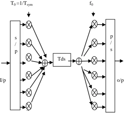
symbol X[k] modulated the subcarrier with the frequency of
𝑓𝑘 = , for N= 6(i.e., k = 0,1,2,3,4,5) while it can be demodulated by using the orthogonality among the subcarriers in the receiver. By using IFFT and FFT, multicarrier modulation can perform at the transmitter as well as for receiver. Parallel Inputs to the multiplier are x[0], x[1], x[2], x[3], x[4], x[5] and outputs are y[0], y[1], y[2], y[3], y[4], y[5].
T0 =1/Tsym f0
I/p o/p
[image:4.595.54.265.161.353.2]x
Figure 2: Block diagram of OFDM modulation and demodulation process for N=6. (Tds---time domain
signals)
4.
OFDM GUARD INTERVAL
Consider the 𝑙𝑡 OFDM signal,𝑥𝑙(𝑡) = 𝑁−1𝑘=0𝑋𝑙[𝑘]𝑒𝑗 2𝜋𝑓𝑘 𝑡−𝑙𝑇𝑠𝑦𝑚 ,
𝑙𝑇𝑠𝑦𝑚 < 𝑡 ≤ 𝑙𝑇𝑠𝑦𝑚 + 𝑛𝑇𝑠 .
For the channel with an impulse response of 𝑙(𝑡), the received signal is given as
𝑦𝑙 𝑡 = 𝑥𝑙 𝑡 ∗ 𝑙 𝑡 = 𝑙 𝜏
∞
0 𝑥𝑙 𝑡 − 𝜏 + 𝑧𝑙(𝑡) , (10)
𝑙𝑇𝑠𝑦𝑚 < 𝑡 ≤ 𝑙𝑇𝑠𝑦𝑚 + 𝑛𝑇𝑠 .
Where 𝑧𝑙(𝑡) is the additive white Gaussian noise (AWGN) process, Taking the samples of equation (10) at 𝑛𝑇𝑠=
𝑛𝑇𝑠𝑦𝑚/𝑁
Equation (9) can be represented in a discrete time as
𝑦𝑙 𝑛 = 𝑥𝑙 𝑛 ∗ 𝑙 𝑛 + 𝑧𝑙 𝑛
𝐴 = ∞𝑚 =0𝑙 𝑚 𝑥𝑙 𝑛 − 𝑚 + 𝑧𝑙 𝑛 (11)
Where 𝑥𝑙 𝑛 = 𝑥𝑙 𝑛𝑇𝑠 , 𝑦𝑙 𝑛 = 𝑦𝑙 𝑛𝑇𝑠 ,
𝑙 𝑛 = 𝑙 𝑛𝑇𝑠 , 𝑧𝑙 𝑛 = 𝑧𝑙 𝑛𝑇𝑠 .
4.1. Cyclic Prefix
Cyclic Prefix is to extend the OFDM symbol by copying the last samples of the OFDM symbol into its front. Let TN denote
the length of CP in terms of samples. Then, the extended OFDM symbols now have the duration of 𝑇𝑠𝑦𝑚 = 𝑇𝑠𝑢𝑏 + 𝑇𝑁 . The length of the guard interval is set longer than or equal to the maximum delay of a multipath channel, then ISI effect of an OFDM symbol is reduced. This indicates that the guard interval longer than the maximum delay of the multipath channel allows for maintain the orthogonality among the subcarriers. As the continuity of each delayed subcarrier has
been guaranteed by the CP, its orthogonality with all other subcarriers is maintained over 𝑇𝑠𝑢𝑏 such that
1 Tsub 𝑒
𝑗 2𝜋 𝑓𝑘(𝑡−𝑡0)𝑒−𝑗 2𝜋𝑓𝑖(𝑡−𝑡0)
Tsub
0 𝑑𝑡 = 0 , 𝑘 ≠ 𝑖
For the first OFDM signal that arrives with a delay of t0 , and
1 Tsub 𝑒
𝑗 2𝜋 𝑓𝑘(𝑡−𝑡0)𝑒−𝑗 2𝜋𝑓𝑖(𝑡−𝑡0−𝑇𝑠)
Tsub
0 𝑑𝑡 = 0 , 𝑘 ≠ 𝑖
For the 2nd OFDM signal that arrives with a delay of t0+Ts,
Figure 3: Cyclic prefix with OFDM symbol
Figure (2) shows that the tail part of the OFDM symbol affects the head part of the next symbol because the length of the cyclic prefix is set shorter than the maximum delay of a multipath channel , causes ISI in the signal.
Figure 4: ISI effect of a multipath channel on OFDM symbols with cyclic prefix length shorter than the
maximum delay of the channel.
Symbol Timing Offset may occur, which keeps the head of an OFDM symbol from fit with the FFT window start point. Now suppose the length is set not shorter than the maximum delay of the channel and the FFT window start point of an OFDM symbol is determined within its cyclic prefix interval. Then the OFDM receiver takes the FFT of the received samples {𝑦𝑙[𝑛 ] 𝑁−1𝑛=0 to hold
𝑦𝑙 𝑘 = 𝑦𝑙 𝑛 𝑁−1
𝑛=0
𝑒− 𝑗 2𝜋𝑘𝑛
𝑁
= 𝑙 𝑚 𝑥𝑙[𝑛 − 𝑚] + 𝑧𝑙[𝑛] 𝑒−
𝑗 2𝜋𝑘 𝑛 𝑁
∞
𝑚 =0 𝑁−1
𝑛=0
= 𝑁−1𝑛=0 ∞𝑚 =0𝑙 𝑚 1
𝑁 𝑋𝑙 𝑖 𝑁−1 𝑖=0 𝑒
𝑗 2𝜋 𝑛 −𝑚 𝑁 𝑒−
𝑗 2𝜋𝑘𝑛 𝑁
+𝑍𝑙[𝑘] (12)
= 𝐻𝑙 𝑘 𝑋𝑙[𝑘] + 𝑍𝑙[𝑘]
Where 𝐻𝑙 𝑘 , 𝑋𝑙 𝑘 , 𝑍𝑙[𝑘] and 𝑌𝑙[𝑘] denote the kth subcarrier
frequency of the lth channel frequency response, transmitted
symbol, noise in the frequency domain and received symbol. Equation (12) indicates that the OFDM symbol is the multiplication of input message by the channel frequency response in the frequency domain.
s / p
Tds
om
ain
[image:4.595.325.537.307.435.2]5.
BIT ERROR RATE (BER) OF OFDM
SYSTEM
The analytical Bit Error Rate expression for M - array QAM signaling in Additive white Gaussian noise and Rayleigh channels are as
𝑃𝑒= 2(𝑀−1) 𝑀𝑙𝑜𝑔2𝑀𝑄
6𝐸𝑏𝑙𝑜𝑔2𝑀
𝑁0𝑀2−1 (13)
𝑃𝑒= 2(𝑀−1) 𝑀𝑙𝑜𝑔2𝑀 1 −
3𝛾𝑙𝑜𝑔2𝑀/(𝑀2−1)
3𝛾𝑙𝑜𝑔2𝑀/(𝑀2−1)+1 (14)
Where 𝛾 and M denote 𝐸𝑏
𝑁0 and the modulation order.
Standard Q function defined as
Q(x) = 1
2𝜋 𝑒
−𝑡2 2 𝑑𝑡
∞
𝑥 (15)
The time domain SNR (𝑆𝑁𝑅𝑡) differs from the frequency domain SNR (𝑆𝑁𝑅𝑓) and it is equal to
𝑆𝑁𝑅𝑡 = 𝑆𝑁𝑅𝑓 + 10 log 𝑁𝑢𝑠𝑒𝑑/N dB (16)
6.
RESUTLS & CONCLUSION
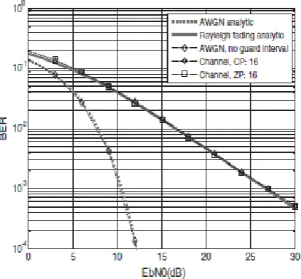
[image:5.595.324.535.76.255.2]The simulation results describe that effect of ISI changes as the length of guard interval varies. It considering that Bit error rate evaluation of an OFDM system with 64 point fast Fourier transform and for 16 bit quadrature amplitude modulation signaling in the Additive White Gaussian Noise fading channels. Bit error rate performance with 16 samples length cyclic prefix is consistent with that of analytical result of Rayleigh fading channel. The length of the guard interval decreases leads more effect of Inter Symbol Interference on Bit error rate performance in the OFDM multicarrier system. Here spectral efficiency of the system is enhanced by using particular length of cyclic prefix or guard period.
[image:5.595.62.274.452.648.2]Figure 5: Bit error rate of OFDM system with guard length equal to 16 bit
Figure 6: Bit error rate of OFDM system with guard length equal to 3 bit
7.
REFERENCES
[1] L. Anupriya and S. Joseph Gladwin, “Channel Estimation for MIMO-OFDM Systems Using Superimposed Training in VLSI,” International Conference on Communication and Signal Processing (ICCSP), pp.763-767, 3-5 April, 2014.
[2] J. Talvitie, T. Levanen, and M. Renfors, “Channel Estimation in Time-Varying Flat-Fading Channel Using Superimposed Pilots with Interference Avoidance,” 2010 7th International Symposium on Wireless Communication Systems (ISWCS), pp. 209-213, 19-22 Sept.2010.
[3] F. Foroughi, F. Karimdady Sharifabad , and O. Edfors, “Low Complexity channel estimation for LTE in fast fading environments for implementation on multi-standard platforms,” Vehicular Technology Conference Fall (VTC 2010-Fall), 2010 IEEE 72nd, pp. 1 – 5, 6-9 Sept.2010
[4] Gajanan R patil, Viswanath K Kotake, “Simplified Implementation of Sphere Decoding Algorithms for MIMO Wireless Communication System”. Advances in Energy Aware Computing and Communication Systems” In Proc.ICECCS-2013, 17-19 Oct2013,pp 128-137.
[5] G.L. Stuber, J.R. Barry, S.W. McLaughlin, Y.G. Li, M.A. Ingram, and T.G. Pratt, “Broadband MIMO-OFDM wireless communication,” Proc. IEEE, vol.92, no.2, pp.271-294,Feb 2004.
[6] F. Wan, W.P. Zhu, and M.N.S. Swamy, “A semi blind channel estimation approach for MIMO-OFDM systems,” IEEE Trans. Signal process. vol.56, no.7, pp.2821-2834, Jul.2008.
[7] M. Biguesh and A. B. Gershman, “MIMO channel estimation: optimal training and tradeoffs between estimation techniques,” in Proc. of IEEE International Conference on Communications, 2004, vol. 5, pp. 2658– 2662.
[9] H. Bolcskei and A. J. Paulraj, “Space-frequency coded broadband OFDM systems,” In Proc. IEEE WCNC, vol. 1, 2000, pp. 1–6.
[10] Jeffrey G. Andrews, Arunabha Ghosh, and Rais Mohamed, “Fundamentals of WiMAX: Understanding Broadband Wireless Networking,” Prentice Hall, 2007.
[11] Roger B. Marks, “The IEEE 802.16 Wireless MAN Standard for Wireless Metropolitan Area Networks”, IEEE C802.16-02/09.