Performance of FSO Links for BPSK Modulated Signal
with Atmospheric Turbulence and Pointing Error
Simran Kaur
Student
Department of Electronics and Communication
Bharati Vidyapeeths College of Engineering
Priyanka Bhardwaj
Faculty
Department of Electronics and Communication
Bharati Vidyapeeths College of Engineering
ABSTRACT
Free-Space Optical communications (FSO) propagated over a clear atmosphere suffers from irradiance fluctuation caused by small but random atmospheric temperature fluctuations. This results in decreased Signal-to-Noise Ratio (SNR) and consequently impaired performance. In this paper, the Bit Error Rate (BER) performance of FSO communication systems employing Binary Phase Shift Keying (BPSK) modulation is derived. To evaluate the system error performance in weak turbulence regime, the Probability Density Function (pdf) of the received irradiance after traversing the atmosphere is modeled using the log normal distribution. The effects of pointing errors on the performance of a FSO communication system are studied
General Terms
Free Space Optical communication (FSO), Binary Phase-Shift Keying (BPSK), Pointing Error.
Keywords
Atmospheric turbulence, diversity, Free-Space Optics (FSO), log normal channel model, Binary Phase-Shift Keying (BPSK), Bit-Error Rate (BER), Signal-to-Noise Ratio (SNR), misalignment fading, pointing error
.
1.
INTRODUCTION
FSO communication channels provide several advantages over Radio Frequency (RF) channels. They offer high bandwidth, secure transmission, and more freedom from interference. Further, these links can be established with components of smaller size and weight. However, there are two major issues with FSO links. First, they are affected by the atmospheric channel conditions such as scattering, absorption, and turbulence. Second, FSO links require accurate pointing. [1]
The FSO system consists of the transmitter, receiver and atmospheric channel as a medium of propagation. FSO system can exhibit characteristics of reflective, refractive, diffusional or combinational circuit [2] [3]. It can exhibit another configuration of a simple optic performing a combined function thus saving cost, weight and size.
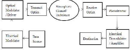
[image:1.595.319.538.221.305.2]FSO basic block diagram is given in figure 1. As shown in the figure 1, there are three main functional elements in FSO that are transmitter, atmospheric channel and receiver.
Figure 1: Free Space Optical Subsystem
At the transmitter, the modulator using different modulation techniques, modulates the information signal and converts the electrical signal to optical signal using the optical source (LED or laser). The most commonly used modulation method is Intensity Modulation. The radiation of LED or laser is aligned by telescope to a collimated beam that is propagated towards the receiver in the transmit optics. Laser is preferred because of the high pointedness and coherence that its beam exhibits. Transmitter converts incoming electrical signal from driver circuit into optical form to be transmitted over the atmospheric channel. [4]
The transmitted signal propagates through the atmosphere where it attenuates due to absorption, scattering and turbulence. The signal attenuate due to harsh weather conditions like rain/snow/haze/fog/turbulence.
At the receiver end, the telescope receives the incoming radiated signal and directs the signal towards optical filter. The optical filter allows passing only the wavelength of the signal and blocks other radiations from the atmosphere. The detector converts the optical signal back to the electrical signal which is directed to the amplifier to amplify the signal. The receiver processing circuits include decision device and clock recovery circuit which recovers the information at the receiver end. Receiver side contains a photo detector which converts the received optical signal to electrical form again which can then be amplified or processed. Modulation and demodulation of the signal takes place in electrical form. Received signal is demodulated and produced in the desired form to the destination. [5]
high rise buildings that causes vibrations of transmitted beam and thus misalignment. Both, scintillation and misalignment of the received beam reduces the performance and reliability of the FSO links. Many techniques, such as, diversity, coding etc. have been suggested to still have carrier class service with FSO link. [6]
There are many different types of modulation schemes which are suitable for FSO communication systems such as On-Off Keying (OOK), Pulse Amplitude Modulation (M-PAM), Differential Phase Shift Keying (DPSK), Binary Phase Shift Keying (BPSK) and Quadrature Phase Shift Keying (QPSK). Since the average emitted optical power is always limited, the performance of modulation techniques is often compared in terms of the average received optical power required to achieve a desired BER at a given data rate. The On-Off keying (OOK) signaling format has been widely used in the IM/DD FSO systems. But in channels with the atmospheric turbulence induced fading, the OOK scheme requires adaptive threshold to perform optimally. This fact among others has led to the increased interest in the study of BPSK in FSO systems. It has also been shown that using a fixed threshold OOK scheme results in suboptimal system, which is not only inferior to another modulated FSO link but also has a BER floor. Although an OOK intensity modulated based FSO link is widely reported, its major challenge lies in the fact that it requires adaptive threshold to perform optimally in atmospheric turbulence condition. In this paper, turbulence channels are described by the log normal probability distribution and then we derive the BER performance of FSO communication system with BPSK modulation. A decision criterion is developed to obtain an optimal threshold for OOK modulation under various turbulent conditions. To circumvent this implementation difficulty and to ameliorate turbulence induced irradiance fluctuation, we consider in this paper the BPSK scheme. The atmospheric turbulence across weak to strong regime is modeled using the log normal distribution. And the noise, which is modeled as additive white Gaussian comprises of both the background radiation and the thermal noise. [7, 8]
2.
SYSTEM AND CHANNEL MODEL
2.1. System Model
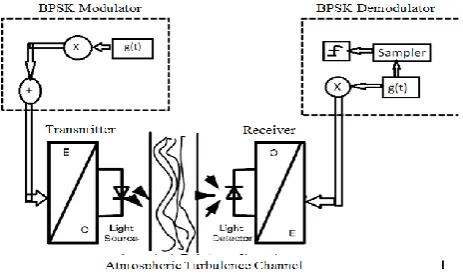
Figure 2 represents the block diagram of BPSK system. The laser beam widths are narrow, but sufficiently wide to illuminate the entire PD array. However, to exploit all potentials of FSO communication systems, the designers have to overcome some of the major challenges related to the optical wave propagation through the atmosphere.
Figure 2: Block diagram of BPSK system [9]
Namely, an optical wave propagating through the air experiences fluctuations in amplitude and phase due to atmospheric turbulence. The transmitter modulates data onto the instantaneous intensity of an optical beam. The received photocurrent signal is related to the incident optical power by the detector responsivity R. It is assumed that the receiver integrates the photocurrent for each bit period and removes any constant bias due to background illumination. The received signal y suffers from a fluctuation in signal intensity due to atmospheric turbulence and misalignment, as well as additive noise, and can be well modeled as [9]
[X][ y] =[ h] [ R] +[ n] (1) where x is the transmitted intensity, h is the channel state, y is the resulting electrical signal, and n is signal independent additive white Gaussian noise with variance 2 n σ .
Again in Figure 2 an optical communication system employing intensity modulation through turbulent atmosphere. For an optical communication system employing BPSK intensity modulation, the data sequence is first modulated with BPSK, which can be implemented with existing microchips at very low cost. Secondly, the BPSK signal is upconverted to an Intermediate Frequency (IF). Then, the modulated electrical
signal is utilized to control the irradiance of optical beam in the transmitter. In the receiver, the optical signal is firstly converted to an electrical signal. Then, the receiver demodulates the electrical signal by using RF devices like selective filters and stable oscillators. At the receiver the received optical intensity P(t) can be written as [9]
P (t ) = I (t ) P (t ) + n (t ) (2) where P0(t) is the received optical intensity without turbulence, and n(t) ~ N(0,σn). It is the Additive White Gaussian Noise (AWGN). I(t) is a stationary random process representing the intensity gain induced by atmospheric turbulence, its probability density function (PDF).
2.2. Channel Models
To maintain the required link performance, a number of models have been proposed. These models are called channel models. These models study the effect of adversaries on the FSO link under turbulent atmosphere. Among these models, the most popular models have been listed viz. gamma-gamma, log normal and negative exponential models. We will be using Lognormal model in this paper.
Lognormal Model:
This model is used for low turbulence conditions and for propagation distances less than 100 m. Considering this model, the pdf of the received optical field I is given as f (I )
f(I)= 1 2𝜋𝐼 𝜎2exp
− ln (𝐼 −𝑚𝑖) 2
2𝜎𝑖2 (3)
where mk is mean and 𝜎𝑖is log-irradiance variance.
Log-irradiance variance is given by𝜎𝑆𝐼2 = 𝑒𝜎𝑖
2
[image:2.595.68.300.597.737.2]Pointing Error
Pointing error is one of the major challenge in FSO communication that can result in link failure. It is very essential to maintain pointing and acquisition throughout the duration of communication. It could arise due to many reasons such as satellite vibration or platform jitter or any kind of stress in electronic or mechanical devices. The effect of satellite vibration in FSO system is described in. Pointing error can also be caused due to atmospheric turbulence induced beam wander effect which can displace the beam from its transmit path. In any of the case, pointing error will increase the chances of link failure or can significantly. reduce the amount of received power at the receiver resulting in high probability of error.[11] In order to achieve sub micro-radian pointing accuracy, proper care has to be taken to make the assembly vibration free and maintain sufficient bandwidth control and dynamic range in order to compensate for residual jitter. Total pointing error, is sum of tracking error and point ahead error. Tracking error is primarily due to the noise associated with tracking sensors or due to disturbances arising from mechanical vibration of satellite.[12] Point ahead error occurs if the calculation of point ahead angle did not allow sufficient transit time from satellite-to-ground and back again. It could be due to error in Ephemeris data or point ahead sensor error or calibration error or waveform deformation. Pointing error loss is more when tracking LEO than GEO satellite. Also, loss due pointing error is more significant at visible wavelength and decreases at higher wavelength due to inherent broadening of beam. Pointing error has significant impact on BER performance of FSO system.[13]
Pointing error is composed of two components: a fixed error, called boresight, and a random error, called jitter. The effect of pointing error in FSO is a crucial issue and, therefore, the optical systems require precise pointing.. The pdf of hp can be
derived using the assumptions and methodology described in. The spatial intensity profile of the beam is assumed to be Gaussian with a beam waist wz , at the receiver plane at a
distance z from the transmitter with a circular aperture of radius r. The fraction of the collected power due to geometric spread with radial displacement α from the origin of the detector can be approximated as[14]
Hp(r,z) ~ A0
exp(-𝛼 .exp(-𝛼 𝑤𝑧𝑒𝑞2
) (4)
where,
𝑤𝑧𝑒𝑞2 = wz2 𝜋erf
(𝑣)
2𝑣 exp (−𝑣.𝑣) (5)
A0 = [erf(v)]2 (6)
v = ( 𝜋𝑎)/( 2 𝑤𝑧) (7)
3.
SIMULATION RESULTS
The BPSK FSO system described above is simulated using Monte-Carlo approach in Matlab 7.5.0 (R2007b). While simulating the pulse shaping function is assumed to be rectangular. The system parameters and that of the atmospheric turbulence and pointing error are given below:
● Data rate 1 Mbps ● Carrier frequency 8 GHz ● Sampling frequency 20 MHz ● Laser wavelength 850 nm ● Photo detector sensitivity 1 ● Optical modulation index 1
● Standard deviation of turbulence 0.23≤ sigma ≤ 2 ● Distance between Tx and Rx (z) 1 Km
[image:3.595.335.549.72.370.2]● Receiver diameter (2a) 20 cm ● Beam radius at 1 km (wz) 2.5 m
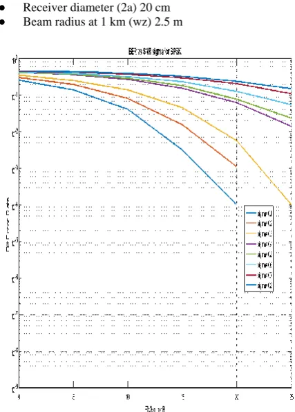
[image:3.595.310.557.418.752.2]Figure 3: BPSK Simulation for different values of turbulence factor
Table 1: Value of BER for SNR = 20 for different values of sigma
Sigma BER
0.1 0.0001
0.2 0.001
0.3 0.01
0.5 0.1
0.8 0.5
As seen from figure 3, we have drawn out table which lists the value of BER for SNR=20 for different values of sigma. It is observed that as the value of sigma increases, the BER increases.
[image:3.595.317.566.575.747.2]Error with Sigma=0.05
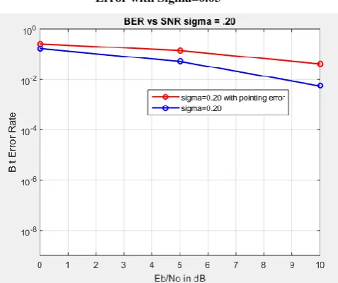
Figure 5: BPSK Simulation with and without Pointing Error with Sigma = 0.20
From Figure 4 and 5, shows the simulation of BPSK modulation scheme for FSO communication for different values of sigma. The blue line graph shows the simulation of BPSK generated signal for Log-Normal channel in FSO communication. The red line graph includes the pointing error in communication. From the graph, we conclude that BER increases in the presence of pointing error.
For SNR=5,
❖ Sigma=0.05
● BER( without pointing error) = 0.001
● BER( with pointing error) = 0.1
❖ Sigma=0.20
● BER( without pointing error) = 0.098
● BER( with pointing error) = 0.2
It can be inferred that BER increases in the presence of pointing error.
4.
CONCLUSION
A number of simulations were carried out using MATLAB 7.5.0 (R2007b). In the first set of simulations, we compare the BER-SNR curve for different values of sigma. The channel is modeled as an AWGN channel with fading incorporated. The channel will thus closely model the conditions in the atmosphere. The variance of the fading is changed to simulate different degrees of turbulence. This research paper provides a comprehensive analysis of Bit Error Rate versus Signal to Noise Ratio for Free Space Optical signal. BPSK modulation scheme has been analyzed regarding both atmospheric turbulence and pointing error effects and simulations are done by incorporating different values of atmospheric turbulence and pointing error. For a specific value of E b /No , bit error
rate has been observed. This parameter is affected by many conditions like choice of modulation scheme, atmospheric turbulences, pointing errors etc. As the turbulence coefficient increases, bit error rate increases. Further, similar atmospheric turbulences also shows increased bit error rate when pointing errors are incorporated. So we can conclude as atmospheric turbulence increases the performance of FSO link goes down and further addition of pointing error along with atmospheric
turbulence worsify the situation.
5.
FUTURE SCOPE
The future scope of this paper is suggested as below:-
Investigate the performance of DPSK in FSO with the use of coding.
Investigate the performance of QDPSK, 8 and 16 DPSK in FSO.
Investigate the performance of QDPSK, 8 and 16 DPSK in FSO with the use of coding.
Use of NRZ and RZ DPSK in the above combinations.
Use of MIMO and spatial diversity with the above combinations
Analyze all above combinations for pointing error along with atmospheric turbulence
6.
ACKNOWLEDGMENTS
Our thanks to the experts who have contributed towards development of the template.
7.
REFERENCES
[1] V. W. S. Chan, “Free-space optical communications,” J. Lightwave Tech., vol. 24, no. 12, pp. 4750–4762, 2006
[2] Arun K Mazumdar,”Free Space Laser Communication Performance in the Atmospheric Channel”, Journal of Optical and Fiber Communication Reports, Reprint 2, pp345-396 (2005)
[3] Arun k.majumdar, “Advanced Free Space Optics (A System Approach)”, New York :Springer Series in Optical Sciences,Vol.186, 2015.
[4] H.A. Willebrandand, B.S. Ghuman, “Fiber optics without fiber,” IEEE Spectrum, vol.38,no.8, pp.40–45, 2001.
[5] H Henniger and O. Wilfert, “An Introduction to Free Space Optical Communications”, Radio Engineering, vol. 19, no. 2, June 2010
[6] M. Uysal and J. T. Li, “BER performance of coded free-space optical links over strong turbulence channels,” in Proc. IEEE Vehicular Technological Conference (VTC spring), May 2004, pp. 168–172.
[7] X. Zhu and J. M. Kahn, "Free-space optical communication through atmospheric turbulence channels," IEEE Transactions on Communications, vol. 50, pp. 1293-1300, August 2002.
[8] W. Huang, J. Takayanagi, T. Sakanaka, and M. Nakagawa, "Atmospheric optical communication system using subcarrier PSK modulation," ICC 93, IEEE International Conference on Communications, Geneva., vol. 3, pp. 1597-1601, May 1993.
[9] Bobby Barua, “Comparison the Performance of Free-Space Optical Communication with OOK and BPSK Modulation under Atmospheric Turbulence”, International Journal of Engineering Science and Technology (IJEST), Vol. 3 No. 5 May 2011, pp 4391-4399.
[11] Harilaos G. Sandalidis, Theodoros A. Tsiftsis, Member, IEEE, George K. Karagiannidis, Senior Member, IEEE, and Murat Uysal, Senior Member, IEEE, “BER Performance of FSO Links overbStrong Atmospheric Turbulence Channels with Pointing Errors” , IEEE COMMUNICATIONS LETTERS, VOL. 12, NO. 1, JANUARY 2008.
[12] A. A. Farid and S. Hranilovic, “Outage capacity optimization for freespace optical links with pointing errors,” J. Lightwave Technol., vol. 25, pp. 1702–1710, July 2007.
[13] S. Arnon, “Effects of atmospheric turbulence and building sway on optical wireless-communication
systems,” Opt. Lett., vol. 28, pp. 129–131, Jan. 2003.
[14] Priyanka Bhardwaj, D. Chadha "Performance of BPSK Subcarrier Intensity Modulated Free Space Optical Communications with Atmospheric Turbulence and Pointing Error" Proceedings of the IASTED International Conference Wireless Communications (WC 2012), July 3 - 5, 2012 Banff Canada.