Fuzzy-Logic Based Speed Control of Induction Motor
Considering Core Loss into Account
Mohammad Abdul Mannan1, Asif Islam2, Mohammad Nasir Uddin1, Mohammad Kamrul Hassan1, Toshiaki Murata3, Junji Tamura3
1Department of Electrical & Electronic Engineering, American International University,
Bangladesh (AIUB), Dhaka, Bangladesh
2Department of Electrical & Electronic Engineering, Bangladesh University of
Engineering & Technology (BUET), Dhaka, Bangladesh
3Department of Electrical Engineering, Kitami Institute, Hokkaido, Japan
Email: [email protected], [email protected], [email protected], [email protected]
Received April 20,2012; revised June 6, 2012; accepted June 14, 2012
ABSTRACT
Rotor flux and torque of an induction motor (IM) are decoupled to obtain performance of DC motor. The decoupling strategy has been developed in terms of stator current components where the core loss is neglected. Many different con- trollers including fuzzy logic controller (FLC) with neglecting core loss have been designed to control the speed of in- duction motor. The outcome of investigation about the effect of core loss on indirect field oriented control (IFOC) has been concluded that the actual flux and torque are not reached to the reference flux and torque if core loss is neglected. Thus, the purpose of this paper is to propose a fuzzy logic speed controller of induction motor where flux and torque decoupling strategy is decoupled in terms of magnetizing current instead of stator current to alleviate the effects of core loss. The performances of proposed fuzzy-logic-based controller have been verified by computer simulation. The simu- lation of speed control of IM using PI and FLC are performed. The simulation study for high-performance control of IM drive shows the superiority of the proposed fuzzy logic controller over the conventional PI controller.
Keywords: Indirect-Field-Oriented Control; PI Controller; Fuzzy Logic Controller; Induction Motor; Speed Control
1. Introduction
Induction motors have been considered for many indus- trial applications since its discovery [1-3] because of its low maintenance, robustness, low cost, high efficiency, good self starting, simplicity of design, absence of the collector brooms system and small inertia. The most pro- blematic things of induction motor are its complex, non- linear, multivariable mathematical model, and it is not inherently capable of providing variable speed operation [4,5]. The problems of induction motor can be solved through the use of intelligent control and adjustable speed controllers, such as scalar and vector control drive [6,7].
The scalar control methods like the volt-hertz control performance is good only for steady state condition but it leads to poor dynamic performance. Since Blashke [6] and Hasse [8] have developed the new technique known as vector control or field oriented control (FOC), the use of the induction machine becomes more and more fre- quent because FOC provides better performance for steady state as well as transient conditions. This control strategy can provide the same performance as achieved from a separately excited DC machine, and is proven to
be well adapted to all type of electrical drives associated with induction machines [9].
The FOC schemes are classified into two groups: the direct method of field orientation proposed by Blaschke [6] and the indirect method of field orientation proposed by Hasse [8]. The direct method requires flux acquisi- tion, which is mostly obtained by computation techni- ques using machine terminal quantities, where as indirect method avoids the requirement of flux acquisition by using known motor parameters to compute the appropri- ate motor slip speed to obtain the desired flux position. The scheme of indirect is simpler to implement than the direct method of FOC hence, indirect field oriented con- trol (IFOC) method has become more popular [1,10-13].
loss into account is complicated [18-21]. Therefore, an IFOC method of induction motor drives taking core loss into account in terms of magnetizing current components has been proposed with PI speed controller loop in [22]. The extension work [22] of literature [18] has been done to regulate speed and rotor flux based on PI controller. In [22], the PI controller gains were changed to obtain de- sired speed under the variation of load torque. One set of fixed PI controller gain is unable to track the desired speed. Moreover, the steady state error cannot be mini- mized to zero by the conventional PI controller [16,21]. An IFOC of induction motor drive to regulate speed based on fuzzy-logic has been proposed in [16] neglecting core loss. To overcome the previously discussed disad- vantages of conventional PI controller and the complica- tion effects of core loss of induction motor drive, it would be desirable to design a well controller. The fuzzy- logic control (FLC) is seemed to be a suitable controller in terms of high dynamic response under the variation of load torque and parameters [16].
In this paper, a fuzzy-logic-based high-performance control of IM drive including core loss is proposed. The FLC is used to regulate rotor speed in terms of magnet- izing q-axis current where the reference d-axis current is kept constant at rated value. The proposed controller can track properly the desired speed under the variation of load torque and parameters. The effectiveness of the proposed controller with space vector PWM inverter-fed IM drive is shown by computer simulation which done by Matlab/Simulink. The simulation is also done for PI speed controller of induction motor taking core loss into account. The simulation study shows the superiority of the proposed FLC over the conventional PI controller.
[image:2.595.322.520.87.173.2] [image:2.595.129.287.581.685.2]2. IFOC of Induction Motor Drive Taking
Core Loss into Account
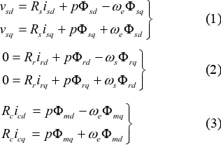
Figure 1 shows the equivalent circuit of an induction motor taking core loss into account in the d-q axes syn- chronously rotating reference frame. The voltage equa- tions are given by:
Φ Φ
Φ Φ
sd e sq
sq e sd
p p
Φ Φ
Φ Φ
rd s rq
rq s rd
Φ Φ
Φ Φ
md e mq
mq e md
j
sd s sd
sq s sq
v R i v R i
(1)
0 0
r rd
r rq
R i p R i p
(2)
c cd
c cq
R i p
R i p (3) where p is differential operator; vsd and vsq are the stator d- and q-axis input voltages; isd and isq are the stator d- and q-axis currents; ird and irq are the rotor d- and q-axis currents; icd and icq are the core loss d- and q-axis cur-
mm
is
vs
Rs
Rc
Rr Lrl
Lsl
Lm
j jsLrl ri
j
eLslis
em i
i c r
i m
sd rd cd md sq rq cq mq i i i i i i i i
[image:2.595.354.538.630.708.2]Φ Φ ; Φ Φ
Figure 1. Equivalent circuit of IM taking core loss into ac- count in a synchronously rotating reference frame.
rents; sd and sq are the stator d- and q-axis fluxes; rd and rq are the rotor d- and q-axis fluxes; md and mq are the magnetizing d- and q-axis fluxes; Rs, Rr and Rc are stator, rotor and core loss resistances; e and s are primary and slip angular frequencies.
The current equations are written as
(4)
where, imd and imq are the magnetizing d- and q-axis cur- rents. The flux equations are given as
d L isl sd md sq L isl sq mq
s
Φrd L irl rd Φmd; Φrq L irl rq Φmq
(5)
Φmd L im md; Φmq L im mq
(6) (7)
where, Lsl is stator leakage inductance; Lrl is rotor leak- age inductance; Lm is magnetizing inductance; Ls is stator self inductance; Lrl is rotor self inductance.
The mechanical dynamic system and developed torque are given as
m m n e L
p D J P J T T (8)
Φ Φ
e n m rl mq rd md rq
T P L L i i
Φrd Constant; Φrq 0
(9)
where, m is rotor angular frequency; Te and TL are elec- tromagnetic and load torques; Pn is number of pole pair; J is moment of inertia; and D is damping factor.
The main feature of IFOC method is given as follows: (10)
According to the FOC constrains of Equation (10), the core loss current rotor flux, torque and slip can be ob- tained
;
cd m e mq c cq m e md c i L i R i L i R (11)
Φrd Lm
i
sdi
cd (12)
Φ
e n m rd r sq cq
T P L L i i (13)
Φ
s R Lr m Lr rd isq icq
(14)
0 3 6 8.92
8.94 8.96 8.98 9.00 9.02 9.04
9 12 15
Stator
d
-a
xi
s Current
[A
]
Torque [N-m]
Calculated desired isd without Rc
Calculated desired isd with Rc
12 15
(a)
0 3 6 9
0 3 6 9 12 15 18
St
at
or
q
-a
xi
s Cur
re
nt
[
A
]
Torque [N-m] Calculated desired i
sq without Rc Calculated desired isq with Rc
Φrd L im md
[image:3.595.88.253.82.353.2](b)
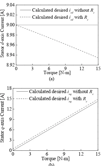
Figure 2. Steady state stator current for different torque at rated speed. (a) Stator d-axis current; (b) Stator q-axis current.
with and without consideration of core loss. This calcula- tion has done by using the parameters which are given in Table 1. The calculation of stator d-axis current to con- trol flux and stator q-axis flux to control torque are not same of practical one. The decoupling control of IM in terms stator currents will not be met as shown in Equa- tions (11)-(13) and Figure 2, because in practical IM core loss currents icd and icq are not zero. The rotor flux, torque and slip in terms of magnetizing current are [18].
(15)
Lm Lrl
imqΦrde n
T P (16)
Φ
s R Lr m Lrl imq rd
(17)
From Equations (15)-(17), it is seen that the decoup- ling control of torque and rotor flux of IM taking core loss into account can be designed easily in terms of mag- netizing current components instead of stator current com- ponents. PI based speed controller is proposed in [18] to obtain imq for regulating rotor speed where the reference rotor d-axis flux is kept constant at rated value.
3. Design of a PI Controller
The use of PI control has a long history in control engi- neering and is acceptable for many real industrial appli- cations. Hence, PI control is still the commonly used control technique in the industrial applications despite
Table 1. Ratings and parameters of induction motor.
3 hp, 1430 rpm, 14.96 N-m, 4 pole, 50 Hz
Rs = 0.55 , Rr = 0.75 , Rc = 320 ,
Lsl = 5 mH, Lrl = 5 mH, Lm = 63 mH,
J = 0.0179 Kg·m2, D = 0.001 N-m-s
the development of the advanced control techniques. The main reasons for this popularity are that PI controllers are often effective and are easy to maintain by plant person- nel. The structure of PI controller is relatively simple which can be easily understood and implemented in prac- tice.
Due to these merits of PI controller, it has applied to control speed, torque and current of IM control in Indus- trial applications [2,3].
In this paper, discrete-time PI controller is designed to achieve the desired speed. The discrete-time PI controller can be defined by the following expression to calculate the first difference of desired q-axis magnetizing current components.
mq I P m
i k K e k K k
(18)
m
m
e k k k , where,
1
m k m k m k
,
1
mq mq mq
i k i k i k
mq i
where, k is sampling instant, KP and KI indicate the proportional and integral constant respectively for speed controller loop. Superscript * indicates the desired or ref-
erence value.
But the PI controller, where the controller gains are chosen by trial and error method, is not adequate to fol- low the reference speed without steady state error. Also, the PI controller is not robust under the variation of load torque and parameters of IM drive. The disadvantages of PI controller are clarified in the simulation results section. Therefore, we proposed speed controller of IM drive based on FLC to eliminate the steady state error and in- crease the robustness.
4. Design of a Fuzzy Logic Controller
The FLC is proposed to find out the desired magnetizing q-axis current according to reference speed under the variation of load torque and parameters. The magnetizing d-axis current is kept constant which is found out from the constant rated rotor d-axis flux.
It is seen from Equation (14) that the desired magnet- izing q-axis current is a function of error of speed and change of speed error. To adopt , the design of FLC is explained in the following.
4.1. Fuzzification
[image:3.595.323.524.102.148.2]the difference of the actual speed from the desired or reference speed, e(k) and the difference of speed error,
e(k) are the only available controller input linguistic variables. The first difference of magnetizing q-axis cur- rent, mq, is considered as the output linguistic variable. For convenience, the inputs and output of the FLC are scaled with different coefficients K, Ke and Ki respec- tively. The scaling factors K, Ke and Ki are chosen for error of speed, change of error of speed and first differ- ence of magnetizing q-axis current respectively as shown in Figure 3. These scaling factors can be constants or variables and play an important role for FLC design in order to achieve a good response in both transient and steady states. In this work, these scaling factors are con- sidered as constant and are selected by trial and error. The triangular membership functions with overlap used for the input and output fuzzy sets are shown in Figure 4 in which the linguistic variables are represented by NB (Negative Big), NM (Negative Medium), NS (Negative Small), Z (Zero), PS (Positive Small), PM (Positive Me- dium) and PB (Positive Big). The grade of input mem- bership functions can be obtained as follows.
i
x w2x m w (19) where (x) is the value of grade of membership, w is the width and m is the coordinate of the point at which the grade of membership is 1, x is the value of the input va- riable.
4.2. Rule Base
The fuzzy mapping of the input variables to the output is represented by fuzzy IF-THEN rules of the following form:
IF is N and is N THEN
IF is P and is Z THEN
n n
n n
e e
e e
is S
is B
n mq n mq i
i
n i
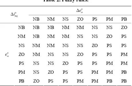
The entire rule base is given in Table 2. There are total 49 rules to achieve desired speed trajectory.
4.3. Inference and Defuzzification
From the rule base in Table 2, the inference engine pro- vides fuzzy value of mq, and then crisp numerical value of mq is obtained by using defuzzification pro- cedure. The most popular method of inference and de-fuzzification is Mamdani’s max-min (or sum-product) composition with center of gravity method [23]. In this work, Mamdani type fuzzy inference [23] is used. The center of gravity method [23] is used for defuzzification to obtain . The normalized output function is given as
i
n mq i
N1 N1i i i
i C i
mq
i n
e
en
(20)
Z-1
imq*
+
1/K
Ke
Ki
imq n
en
[image:4.595.318.527.88.249.2]Standard FLC
Figure 3. Scheme structure of the proposed FLC.
PM PB NM
NB PS NS ZO
0.0 0.50 0.25 1.0
-0.75 -0.50 -0.25 0.75 1.0 -1.0
, ,
n n n
mq
e e i
n
e
[image:4.595.309.539.292.442.2]Figure 4. Fuzzy sets and their corresponding memberships functions.
Table 2. Fuzzy rules.
n mq
i
NB NM NS ZO PS PM PB
NB NB NB NM NM NS NS ZO
NM NB NM NM NS NS ZO PS
NS NM NM NS NS ZO PS PS
ZO NM NS NS ZO PS PS PM
PS NS NS ZO PS PS PM PM
PM NS ZO PS PS PM PM PB n
e
PB ZO PS PS PM PM PB PB
where N is total number rules, i is the membership grade for ith rule and Ci is the coordinate corresponding to the maximum value of the respective consequent membership function [Ci {0.0, 0.9}]. After finding out
mq n i
, the actual desired first difference magnetizing cur- rent, mq
i
, can be found out by product of scaling factor as shown in Figure 3.
5. Simulation Results
In order to verify the performance of proposed fuzzy- logic-based speed control of IM drive, computer simula- tions were performed using Matlab/Simulink. The ratings and parameters of IM drive used are given in Table 1. The sampling period was selected as Ts= 100 sec. In this work, the scaling factors for speed error and change of speed error were chosen as K = rated speed in rad/sec,
Ke= 3 and Ki= rated value of imq. These scaling factors are selected by trial and error to achieve good response in both transient and steady states. We have conducted our simulation work based on Figure 5 where the IM is driven by space vector PWM inverter [22].
0.0 0.5 1.0 1.5 2.0 0
200 400 600 800 1000 1200
Speed [
rpm
]
Time [sec]
Case I: K
P = 0.02; KI = 0.001
Case II: KP = 0.02; KI = 0.01
Case III: KP = 0.0188; KI = 0.143
Reference
0 1 2 3 4
500 600 700 800 900 1000
Figure 5. Proposed FLC-based IM drive.
were performed for both FLC and PI controllers. Figure 6 shows the simulation results based on PI controller for different values of PI controller gains. In these cases ref- erence speed is changed from 0.0 rpm to rated 1000 rpm at 0.0 sec and load torque is changed from 6 to 12 N-m at 1.0 sec.
In Case I of Figure 6, the actual speed follow the ref- erence speed without overshoot but the actual speed can- not follow the reference speed due to the change of load torque. In Case II of Figure 6, where the integral con- stant is increased, the steady state error is occurred be- tween the actual speed and reference speed. In Case III of Figure 6, the actual speed follows the reference speed without steady state error, but overshoot is occurred due to the change of reference speed. It is clear from Figure 6 that the conventional PI controller is not suitable to achieve the desired speed of IM drive without overshoot or steady state error and not robust under the variation of load torque and parameters.
Figure 7 shows the transient responses for indirect- field-oriented control of IM drive using the proposed fuzzy-logic controller with consideration of core loss and without consideration of core loss.
In this simulation work, the step changed from 500 to 1000 rpm at 1.0 sec, load torque changed from 6 to 12 N-m at 2 sec, and again speed changed from 1000 to 500 rpm at 3 sec. It is evident from Figure 6 that the actual speed using proposed FLC follows the reference speed without any overshoot and steady state error. The design controller is also robust under the variation of distur- bance of load torque as shown in Figure 6. If the rotor speed response of Figure 7 is compared with that of Figure 6, it can be clearly understand that the proposed fuzzy-logic controller is better than the conventional PI controller.
Figure 8 shows the transient response of torque. The variation of load torque can be compensated by changing the electromagnetic torque as shown in Figure 8. Figures 9 and 10 show the transient response of rotor flux due to the step changes of reference speed and load torque. It is notified from these figures that the rotor fluxes cannot be
Figure 6. Transient responses for step change of reference speed and step change of load torque using PI controller with different sets of proportional and integral gains.
Sp
ee
d [r
pm
]
Time [sec] With Rc
Without R
c Reference
0 1 2 3 4
2 4 6 8 10 12 14 16 18
Figure 7. Transient responses of speed for step change of reference speed and step change of load torque using FLC.
El
ect
rom
agnet
ic
To
rque [
N
-m
]
Time [sec] With Rc
Without Rc
Load Torque
0 1 2 3 4
0.3 0.4 0.5 0.6 0.7 0.8
Figure 8. Transient response of torque using proposed fuzzy logic control.
Rot
or
d
-a
xi
s fl
ux
[w
b]
Time [sec] With Rc
Without Rc
Reference
0 1 2 3 4 -2
0 2 4 6 8 10
0 1 2 3
-0.2 -0.1 0.0 0.1 0.2
4
Ro
to
r
q
-axis Fl
ux [
w
b]
Time [sec] Referebce With Rc
Without Rc
Reference
q-axis current
d-axis current
Ma
gne
tiz
ing cu
rrent
[A
]
[image:6.595.335.505.84.214.2]Time [sec]
Figure 10. Transient response of q-axis rotor flux using pro- posed fuzzy logic control.
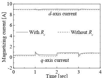
reached to its references values without consideration of core loss. If the field-oriented control is designed without taking core loss into account the constraints of field ori- ented control is not met. Thus the precise torque and flux control is possible by considering the core loss. The pre- cise torque and flux control is possible by decoupling the magnetizing current components rather than the stator current components as shown in Figure 11. The transient response of stator current components is shown in Figure 12. The required stator current components is not reached to decoupling the torque and flux control which is cleared due to the deviations of required current and actual cur- rent. It is clear from Figures 10 and 11 the decoupling control of torque and rotor flux can be achieved in terms of d-axis and q-axis magnetizing current, respectively.
In order to verify the robustness of proposed fuzzy logic controller, the simulation work has been done by varying the change of mutual inductance and rotor resis- tance as shown in Figure 13. From Figures 7 and 13, it is cleared that the proposed fuzzy logic controller is ro- bust under variations of disturbance and parameters.
In order to implement our proposed control system, at first we have to measured the value of core loss resis- tance. How the core loss resistance can be measured and included into the field-oriented control of IM has been discussed in detail in [17-21]. The proposed fuzzy logic controller can be implemented in practical applications based on DSP. The explanation of experiment to imple- ment of FLC based on DSP has been discussed in [16,24].
6. Conclusion
The field oriented control of induction motor with core loss is no longer in terms of stator current components. So, the field oriented control of induction motor is de- signed in terms of magnetizing current. In order to im- prove the performance of an induction motor speed con- troller with consideration of core loss, a fuzzy-logic con- troller for indirect field oriented induction motor drive taking core loss into account is proposed. Due to the
With Rc Without Rc
0 1 2 3 4
[image:6.595.89.252.85.211.2]0 3 6 9 12 15 18
Figure 11. Transient response of magnetizing current using proposed fuzzy logic control.
q-axis current d-axis
current
St
at
or
Curr
ent
[
A
]
Time [sec]
With Rc Without Rc
0.0 0.5 1.0 1.5 2.
Figure 12. Transient response of magnetizing current using proposed fuzzy logic control.
0 0
200 400 600 800 1000
Rotor resistance increased 100% Mutual inductance increased 100%
Speed [
rpm
]
Time [sec]
Mutual inductance increased 50% Reference
1.0 1.5 2.
(a)
992 996 1000 1004
0
(b)
[image:6.595.335.505.254.379.2]consideration of core loss, the FLC is designed to regu- late the speed in term of magnetizing q-axis current component. In order to verify the effectiveness of the proposed FLC, we have conducted simulations using the equivalent circuit of IM in synchronously rotating refer- ence frame. The simulation results based on conventional PI controller and the proposed FLC are demonstrated to compare both of those controllers. At last it can be con- cluded that the performances of the proposed FLC in both transient and steady states are better than those of conventional PI controller.
REFERENCES
[1] P. Vas, “Electrical Machines and Drives: A Space-Vector Theory Approach,” Clarendon Press, New York, 1992. [2] F. Harashima, S. Kondo, K. Ohnishi, M. Kajita and M.
Susono, “Multi-Microprocessor-Based Control System for Quick Response Induction Motor Drive,” IEEE Transac- tion Industrial Applications, Vol. 21, No. 3, 1985, pp. 602-
609.
[3] B. K. Bose: “Motion Control Technology-Present and Fu- ture,” IEEE Transaction on Industrial Applications, Vol.
21, No. 6, 1985, pp. 1337-1342. doi:10.1109/TIA.1985.349587
[4] C.-M. Ong, “Dynamic Simulation of Electric Machinery Using Matlab/Simulink,” Prentice Hall PTR, Upper Sad- dle River, 1998.
[5] A. E. Fitzgerald, et al., “Electric Machinery,” 5th Edition,
McGraw-Hill, New York, 1990.
[6] F. Blaschke, “The Principle of Field Orientation as Ap- plied to the NEW Transvector Closed-Loop System for Rotating-Field Machines,” Siemens Review, Vol. 34, No.
3, 1972, pp. 217-220.
[7] Y. Y. Tzou, “Fuzzy Tuning Current-Vector Control of a Three-Phase PWM Inverter for High-Performance AC Drives,” IEEE Transaction on Industrial Electronics, Vol.
45, No. 5, 1998, pp. 782-791. doi:10.1109/41.720335 [8] K. Hasse, “Zum Dynamischen Verhalten der Asynchron-
machine bei Betriek Mit Variabler Standerfrequenz und Standerspannung,” ETZ-A, Vol. 89, 1968, p. 77.
[9] R. D. Lorenz and D. B. Lawson, “A Simplified Approach to Continuous On-Line Tuning of Field-Oriented Induc- tion Machine Drives,” IEEE Transaction on Industry Ap- plication, Vol. 26, No. 3, 1990.
[10] B. K. Bose, “Power Electronics and Variable Frequency Drives,” IEEE Press Standard Publishers, 1997.
[11] I. Boldea and S. A. Nasar, “Vector Control of AC Drives,” CRC Press, London, 1992.
[12] W. Leonhard, “Control of Electric Drives,” Springer Ver-
lag, Berlin, 1985.
[13] R. Krishnan, “Electric Motors Drives Modeling Analysis and Control,” Publication Prentice Hall of India, New Delhi, 2002.
[14] A. Mechernene, M. Zerikat and M. Hachblef, “Fuzzy Speed Regulation for Induction Motor Associated with Field-Oriented Control,” IJ-STA, Vol. 2, No. 2, 2008, pp. 804-817.
[15] R. Marino, S. Peresada and P. Valigi, “Adaptive Input- Output Linearizing Control of Induction Motors,” IEEE Transaction on Automation, Vol. 38, No. 2, 1993, pp. 208-
211.doi:10.1109/9.250510
[16] M. N. Uddin, T. S. Radwan and M. A. Rahman, “Per- formances of Fuzzy-Logic-Based Indirect Vector Control for Induction Motor Drive,” IEEE Transaction on Indus- trial Applications, Vol. 38, No. 5, 2002, pp. 1219-1225.
[17] I. Boldea and S. A. Nasar, “Unified Treatment of Core Losses and Saturation in the Orthogonal-Axis Model of Electrical Machines,” Proceedings of Institute of Electri- cal Engineers, Vol. 134-B, No. 6, 1987, pp. 355-363.
[18] E. Levi, “Impact of Iron Loss on Behavior of Vector Controlled Induction Machines,” IEEE Transaction on Industrial Application, Vol. 31, No. 6, 1995, pp. 1287-
1296.doi:10.1109/28.475699
[19] E. Levi, A. Boglietti and M. Lazzari, “Comparative Study of Detuning Effects in Indirect Vector Controlled Induc- tion Motor Drives Due to Iron Losses,” Proceedings of International Conference on Power Electronics and Drive Systems, Liverpool, 21-24 February 1995, pp. 633-638.
[20] E. Levi, “Rotor Flux Oriented Control of Induction Ma- chines Considering the Core Loss,” Electric Machine and Power Systems, Vol. 24, 1996, pp. 37-50.
doi:10.1080/07313569608955658
[21] E. Levi, “Iron Loss in Rotor-Flux-Oriented Induction Machines: Identification, Assessment of Detuning, and Compensation,” IEEE Transaction on Power Electronics, Vol. 11, No. 5, 1996, pp. 698-709.
doi:10.1109/63.535402
[22] M. A. Mannan, T. Murata, J. Tamura and T. Tsuchiya, “Indirect Field Oriented Control for High Performance Induction Motor Drives Using Space Vector Modulation with Consideration of Core Loss,” Proceedings of PESC’03,
Acapulco, 15-19 June 2003, pp. 1449-1454.
[23] D. Driankov, H. Hellendoorn and M. Reinfrank, “An Introduction to Fuzzy Control,” Springer-Verlag, Berlin, 1993.
[24] S. Tunyasrirut, T. Suksri and S. Srilad, “Fuzzy Logic Con- trol for a Speed Control of Induction Motor Using Space Vector Pulse Width Modulation,” World Academy of Sci- ence, Engineering and Technology, No. 25, Topics 14,