Reflex
Diako Mardanbegi
Lancaster University, UK [email protected]
Christopher Clarke
Lancaster University, UK [email protected]
Hans Gellersen
Lancaster University, UK [email protected]
ABSTRACT
Gaze depth estimation presents a challenge for eye tracking in 3D. This work investigates a novel approach to the problem based on eye movement mediated by the vestibulo-ocular reflex (VOR). VOR stabilises gaze on a target during head movement, with eye movement in the opposite direction, and the VOR gain increases the closer the fixated target is to the viewer. We present a theoretical analysis of the relationship between VOR gain and depth which we investigate with empirical data collected in a user study (N=10). We show that VOR gain can be captured using pupil centres, and propose and evaluate a practical method for gaze depth estimation based on a generic function of VOR gain and two-point depth calibration. The results show that VOR gain is comparable with vergence in capturing depth while only requiring one eye, and provide insight into open challenges in harnessing VOR gain as a robust measure.
CCS CONCEPTS
•Human-centered computing→Gestural input;
KEYWORDS
Eye tracking, eye movement, VOR, fixation depth, gaze depth esti-mation, 3D gaze estimation
ACM Reference Format:
Diako Mardanbegi, Christopher Clarke, and Hans Gellersen. 2019. Monoc-ular Gaze Depth Estimation using the Vestibulo-OcMonoc-ular Reflex. In2019 Symposium on Eye Tracking Research and Applications (ETRA ’19), June 25–28, 2019, Denver , CO, USA.ACM, New York, NY, USA, 9 pages. https: //doi.org/10.1145/3314111.3319822
1
INTRODUCTION
Gaze depth estimation is a central problem for 3D gaze tracking and interaction. Where a 3D model of the environment is available, depth can be derived indirectly from the position of the first object a gaze ray cast into the environment intersects [Cournia et al. 2003; Tanriverdi and Jacob 2000]. However such a model is not always available or sufficient, for example when gaze is tracked relative to natural environments [Gutierrez Mlot et al. 2016], or when the gaze ray intersects multiple objects positioned at different depths
Permission to make digital or hard copies of all or part of this work for personal or classroom use is granted without fee provided that copies are not made or distributed for profit or commercial advantage and that copies bear this notice and the full citation on the first page. Copyrights for components of this work owned by others than ACM must be honored. Abstracting with credit is permitted. To copy otherwise, or republish, to post on servers or to redistribute to lists, requires prior specific permission and/or a fee. Request permissions from [email protected].
[image:1.612.360.521.132.300.2]ETRA ’19, June 25–28, 2019, Denver , CO, USA © 2019 Association for Computing Machinery. ACM ISBN 978-1-4503-6709-7/19/06. . . $15.00 https://doi.org/10.1145/3314111.3319822
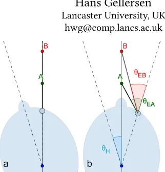
Figure 1: Effect of target distance on VOR. Rotation of the head to target A (θH) is compensated by eye rotation in the opposing direction (θEA). As the eyes are nearer the target, they have to rotate faster than the head. This effect, the VOR gain, decreases with target distance (θEB).
causing target ambiguity [Deng et al. 2017; Mardanbegi et al. 2019]. It is therefore of interest to estimate fixation depth directly based on information from the eyes. Prior work has suggested vergence, accommodation, and miosis as available sources of such informa-tion [Gutierrez Mlot et al. 2016], i.e. the simultaneous movement of the eyes in opposite direction for binocular vision, the curvature of the lens, or the constriction of the pupil. In this work, we investigate the potential of VOR, the stabilising movement of the eyes during head movement based on the vestibulo-ocular reflex, as a temporal cue and alternative information source for gaze depth estimation. Target distance is known to influence VOR [Biguer and Prablanc 1981; Collewijn and Smeets 2000]. When a user rotates their head during fixation on a target, the eyes perform a compensatory rota-tion in the opposite direcrota-tion. As the eyes are closer to the target, their angular movement is larger than the simultaneous movement of the head. The eyes therefore have to move faster and the velocity differential is known asVOR gain. Figure 1 illustrates the effect of target distance on VOR gain: aligning the head with targets A and B involves the same degree of head rotation, while the VOR rotation of the eye is larger for A than for B. The nearer the target, the larger the VOR gain.
travels through an angular range during VOR), and by user variables (variance in head-eye geometry). We then proceed to empirical work to validate the model, based on a data collection with 10 participants using a virtual environment, in which we sampled VOR at target distances from 20 cm to 10 m. Based on insight from the empirical data, we propose measurement of pupil centre velocity for capturing VOR gain, and develop a gaze depth estimation method based on a generic function and two-point depth calibration.
Both our theoretical and practical evaluation of VOR gain are conducted in comparison with vergence. Our results show that VOR gain and vergence behave similarly in relation to gaze depth, leading us to propose a generic model (in the form of a rational function) that can be used for gaze depth estimation with both VOR gain or vergence. A potential advantage of VOR gain over vergence is that it requires tracking of only one eye. However our results also give detailed insight into limitations and challenges of harnessing VOR gain due to the temporal nature of the cue and complex interaction between head and eyes during VOR.
2
RELATED WORK
Previous works on 3D gaze estimation that are based on computing the fixation depth can be categorised depending on how they utilise the information obtained from the eyes and whether they infer the gaze depth directly or indirectly:
Gaze ray-casting methods: These methods primarily rely on
ray-casting a single gaze ray (from either the left or the right eye or the average of both rays shot from an imaginary cyclopean eye situated midway between the two eyes) with the 3D scene where the intersection of the first object in the scene and the gaze ray is taken as the 3D point of regard, e.g. [Cournia et al. 2003; Mantiuk et al. 2011; Tanriverdi and Jacob 2000]. These techniques rely on 3D knowledge of the scene and are only possible if the gaze ray directly intersects an object. They also do not address the occlusion ambiguity when several objects are intersecting the gaze ray as they don’t measure the fixation depth directly. In contrast to those methods that require prior knowledge of the scene, Munn and Pelz used the gaze ray of a single eye sampled at two different viewing angles to estimate the 3D point-of-regard [Munn and Pelz 2008]. However, this method relies upon robust feature tracking and calibration of the scene camera in order to triangulate 2D image points in different keyframes.
Vergence-based methods: Using the eyes’ vergence has been
com-monly used for gaze depth estimation. Unlike ray-casting methods, vergence-based techniques do not rely on information about the scene, instead detecting and measuring the phenomena of the eyes simultaneously moving in opposite directions to maintain focus on objects at different depths. Techniques that directly calculate the vergence can estimate the 3D gaze point by intersecting multiple gaze rays from the left and the right eyes [Duchowski et al. 2001; Hennessey* and Lawrence 2009]. Alternatively, vergence can be calculated indirectly, such as techniques that obtain the 3D gaze point via triangulation using either horizontal disparity between the left and the right 2D gaze points [Alt et al. 2014a; Daugherty et al. 2010; Duchowski et al. 2014, 2011; Pfeiffer et al. 2008] or the inter-pupillary distance [Alt et al. 2014b; Gutierrez Mlot et al. 2016;
Ki and Kwon 2008; Kwon et al. 2006]. Others have used machine learning techniques to estimate gaze depth from vergence [Orlosky et al. 2016; Wang et al. 2014]. All vergence-based techniques rely on binocular eye tracking capabilities. The range of distances at which changes of the vergence angle are measurable within an acceptable experimental error limits the design and evaluated of gaze distances to less than (approx.) 1.5m. Weier et al. [Weier et al. 2018] introduced a combined method for gaze depth estimation where vergence measures are combined with other depth measures (such as depth obtained from ray casting) into feature sets to train a regression model to deliver improved depth estimates upto 6m.
Accommodation-based methods: It is also possible to estimate
gaze depth without knowledge of the gaze position. The accommo-dation of the eyes - the process of changing the curvature of the lens to control optical power - can be measured using autorefractors to infer the gaze depth [Mercier et al. 2017]. Another example is the work by Alt et al. [Alt et al. 2014a], which used pupil diame-ter to infer the depth of the gazed target when indiame-teraction with stereoscopic content. This technique is based on the assumption that the pupil diameter changes as a function of accommodation given that lighting conditions remain constant [Stephan Reichelt 2010]. Common to these techniques is that the required information can be inferred from the information obtained from a single eye only. However, bulky bespoke devices are required to accurately measure the eye’s accommodation, which are not easily integrated into head-mounted displays.
Vestibulo-ocular reflex:The relationship between VOR gain and
fixation depth has been studied in-depth in the fields of physiology and neuroscience, e.g. [Angelaki 2004; Clément and Maciel 2004; Hine and Thorn 1987; Paige 1989; Viirre et al. 1986]. The main goal in these fields is to study the exact mechanisms behind the VOR, and hypothesise how VORs are generated based on sensory information. Viirre et al. studied how actual VOR performed against an ideal VOR, using three Macuca fuscicularis monkeys [Viirre et al. 1986]. By considering the ideal relationship between eye and head angles, they examined the mechanism of VOR, and the effect of target depth and radius of rotation on the VOR gain. Around the same time, Hine and Thorn used human subjects to investigate near fixation VOR targets by developing a similar theoretical model for VOR gain [Hine and Thorn 1987]. In addition, they found that high-frequency horizontal head oscillations were found to markedly affect the VOR gain and that the eyes lagged the head movement by a significant amount at higher frequencies of head oscillations (> 3Hz). These early works demonstrated how target distance affects the VOR gain for angular horizontal movements. Recent work showed that the effect can be used for resolving target ambiguity when gaze is used for object selection in virtual reality [Mardanbegi et al. 2019]. This work, in contrast, presents a fundamental investigation of VOR for gaze depth estimation for which we build on a theory developed in other fields, i.e. theoretical models of how ideal VOR movement is generated.
3
VOR GAIN & FIXATION DEPTH
Figure 2: Basic geometry (top-view) of two eyes fixating on a point (PoR) when the head rotated to the right byθHdegrees around the pointO.
a VOR movement, see Figure 2. This model is inspired by previous work from the fields of vision science and physiology [Hine and Thorn 1987; Viirre et al. 1986]. It assumes the user is fixating on a point of regard (PoR) located at distanceDfrom the centre of rota-tion of head, when the head is turned slightly to the right. All angles are relative to the neutral position when the centre of rotation of the head (O), mid-point of the eyes (H), andPoRare collinear. We assume that head movement is purely due to horizontal rotation, and that the centre of rotation of the head (O) is located at the vertebral column.
During VOR eye movements, the head and the eyeballs can be considered as two coupled counter-rotating objects in 3D where both rotate together but in opposite directions. The gain of the VOR eye movement (VG) is defined as the ratio of angular eye velocity to angular head velocity, defined by:
V G=dθE
dθH. (1)
WhereθEandθHare rotations of the eye and the head respectively. As a result of the offset between the centre of rotation of the eye and the head, and the fact that the eyes are carried by the head during head movements, the angular displacement of the eyes,θE, varies by a small amount,ε, compared with the angular displacement of the head,θH:
θE=θH+ε (2)
More specifically,εrepresents the amount that the gaze direc-tion rotates in space during VOR while the fixadirec-tion point is fixed. AssumingθH is fixed,εchanges as a function of fixation depth,D, and the radius of rotation,r[Viirre et al. 1986]. According to the geometry, the relationship betweenθHandθEfor both the left,θEl, and right,θEr, eyes can be derived by the following equations:
θEr =atan
(D+r)sin(θH)−I2
(D+r)cos(θH)−r
θEl =atan
(D+r)sin(θH)+I
2
(D+r)cos(θH)−r
(3)
The VOR gain can be obtained by differentiating the two sides of the equations above with respect to the angular head velocity. For
20 40 60 80 100 120 140
D [cm] 1.1
1.2 1.3 1.4 1.5
V
G
r=8.8 cm , θH=0∘
r=8.8 cm , θH=20.3∘
r=6.8 cm , θH=0∘
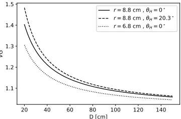
Figure 3: Changes of VOR gain (for right eye) at different target distances for different values ofθHandr. The distance between the two eyeballs (I) is set to 6.5 cm [Poston 2000].
example, the VOR gain for the right eye (V Gr) can be expressed as follows:
V Gr =dθEr
dθH =
2(D+r) (2D−Isin(θH) −2rcos(θH)+2r) (I−2(D+r)sin(θH))2+4(r− (D+r)cos(θH))2
(4) Figure 3 shows how the VOR gain is a function of target distance as well as three other variables: the head angle (θH) at which the gain is measured, the radius of rotation (r), and the inter-ocular separation (I). In the following sections, we discuss how these parameters affect the VOR gain at different fixation depths using the theoretical geometric model.
3.1
Effect of Head-angle on VOR Gain
An important assumption of the proposed method, is that the fixa-tion depth is calculated at a given value ofθH. Figure 4 shows how the VOR gain defined in Eq.4 changes for differentθH at different fixation depths. Up to distances of∼2 m, VOR gain decreases as the distance increases, indicating that the angular velocity of the eye
−40 −30 −20 −10 0 10 20 30 40 θH
1.0 1.1 1.2 1.3 1.4 1.5
VO
R g
ain
D=20 cm
D=30 cm
D=60 cm D=100 cm
D=200 cm
D=1000 cm 0.0
2.5 5.0 7.5 10.0 12.5 15.0 17.5
Ve
rge
nc
e a
ng
le
[image:3.612.63.285.88.206.2]VGr VGl Vergence
[image:3.612.346.529.515.633.2]becomes higher than the angular velocity of the head at smaller fix-ation distances as the eye has to rotate a larger angle. The maximum VOR gain happens at a head angle where the eye centre, the centre of rotation of the head (O), and the PoR are collinear. Either side of this point the VOR gain symmetrically decreases. This peak is slightly shifted for the right and the left eye due to the inter-ocular separation. We refer to the head angle at which the peak VOR gain occurs as thePeak-Gain angle(θH =θEr ≃+20.3◦for the right eye andθH =θEl ≃ −20.3◦for the left eye). The distance between the eye and the target is minimal at the Peak-Gain angle. The re-lationship between VOR gain and head angle implies that gaze depth estimation using VOR gain works best at peak-gain angles as the wider range of changes in the gain could better differentiate the fixation depth value. The VOR gain is close to unity for target distances greater than∼2 m regardless of the head angle.
In Figure 3, we show the changes ofV Gr (solid line) at the peak-gain angle of the right eye at different distances. The radius of rotationris set to 8.8 cm which is the distance between the centre of rotation of the head (i.e. vertebral column) and the centre of the eyeballs [Clément and Maciel 2004; Ranjbaran and Galiana 2012]. The distance between the two eyeballs (I) is also set to 6.5 cm [Poston 2000]. To better illustrate the effect ofθH on the VOR gain, we have also shown the VOR gain curves (dashed lines) for
θH =0◦which is about 20◦off from the peak-gain angle.
3.2
Effect of User Variables
The remaining two variables which the VOR gain is dependent on are user-specific variables:
•Distance from centre of rotation to eyes (r)
•Inter-ocular separation (I)
While pure horizontal head rotations are typically done around the vertebral column (∼8.8 cm behind the eyes), the axis of rotation may shift depending on how the user performs the head rotation. In this geometric model, we assume the user performs a horizontal rotation with a fixed centre of rotation. In the next section, we dis-cuss how this assumption holds up using real-world data. Figure 3 shows how the values ofV Gare affected by varying the distance of the eyes to the centre of rotation for radii of 8.8 and 6.8 cm. We can see that the gain decreases by decreasing the radius of rotation even by a small amount (2 cm).
Changes to the inter-ocular separation affect the angle at which Peak-Gain can be found. Ideally, having values for bothr andI, would simplify the calculation of gaze depth estimation. However, it is not feasible to accurately acquire these values in a practical manner. In the rest of the paper, we discuss how to derive the gaze depth estimation empirically from real-world data without the need to know these valuesa priori.
3.3
Comparison with Vergence
Vergence is traditionally used for gaze depth estimation. To compare the VOR gain technique with vergence in terms of their relation with target depth, we derived the vergence equation from the ge-ometry in Figure 2. The vergence angle (α) is defined as the angle between the left and the right gaze rays, which is derived by:
α=εr+εl =θEr+θEl (5)
The full equation can then be derived by substitutingθEr and
θEl obtained from Eq.3 after switching the sign of the termθErto negative. The vergence angle is measured in degrees, while the VOR gain is unitless. The comparison is shown in Figure 4 where both the vergence angle and the VOR gain of the right eye are plotted at different head angles and for different distances. We can see that both vergence and VOR gain behave similarly against changes in the head angle and target distance. It is interesting to note that the VOR gain provides similar output as vergence, but using the information obtained from only one eye. Approximately 80% of the total changes of VOR gain (at peak-gain angle) or vergence occur between 20 to 100 cm, demonstrating that we have a much higher resolution of gaze depth estimation in this range.
For the rest of the paper, we consider vergence as a baseline to compare the VOR gain method against. However, the vergence angle is rarely directly used for gaze depth estimation. As mentioned in Section 2, the majority of the previous vergence-based methods assess this angle indirectly from geometrical calculations based on the interpupillary distance (IPD) - the distance between the centre of the two pupils as captured by an eye camera. The relationship between IPD and depth may differ to what we have shown forα
due to the cornea refraction and the offset between the visual and optical axes of the eyes.
4
RECORDING GAZE AND HEAD
MOVEMENTS
To investigate how the VOR gain technique works with real-life data we collected a dataset of participants performing a shaking head gesture whilst fixating on a target at different depths. The record-ings were conducted in a virtual reality environment, whereby the eye movement and head positions could be accurately recorded, and the position of the target fixed at different depths. In addition, we measured the distance between the pupil positions of the right and left eyes to calculate the fixation depth based on vergence.
4.1
Setup & Apparatus
A commercially available HTC Vive virtual reality setup with an integrated Tobii eye tracker was used to collect eye and head move-ment data. The program used for the experimove-ment was developed using the Unity engine. Both eye and head data were collected at 120Hz and were synchronised by the Tobii SDK. No other extra equipment’s were used in the experiment.
4.2
Participants & Procedure
Before each recording, the participants conducted a gaze calibra-tion with five points using the default Tobii calibracalibra-tion procedure. The participants were sat on a chair in a comfortable manner with their head facing straight ahead. After a short training session, the participants went through 18 trials with different target depths in each trial, ranging from 20 cm up to 10 m. The task in each trial was to fixate on a target and to move the head 6 times in the transverse plane (akin to shaking the head "no"). The same procedure was repeated twice for each participant.
At the beginning of the recording, a white colour target with a cross at its centre was shown at 70 cm. To help participants align their head with the target at the beginning of each trial, a cross was shown in the centre of their view at the same depth as the target and they were instructed to keep the centre of the cross aligned with the centre of the target. Participants were also asked to keep their gaze fixed at the centre of the target at all times. The target was then moved closer towards the head and stopped at the first distance (20 cm). This converge-assist step with 6 second duration was used to help the user converge the eyes at such a close distance, which could otherwise be very difficult for some people. The participants were instructed to start moving their head when the target turned green. To ensure that head movements were done in the transverse plane, the participants were instructed to keep the horizontal line of the cross aligned with the target during the movement. The head rotation was limited to±20◦from the centre position, and the target became red as soon as the head angle exceeded this angle to indicate to the participant that they should stop the movement and reverse the direction. A tick-tack sound was played in the background to guide the participants to adjust the speed of the movement by aligning the tick-tack sounds with extreme right and left angles. The desired speed for the head shake was set to 50◦/sec(0.4◦/f rame). This value was decided empirically during a pilot experiment using 4 different speeds (30,40,50, and 60)[◦/sec]where 50◦/secyielded smoother side-to-side head movements and it was not too fast for the users. After 10 side-to-side head movements, the target became white indicating that the user can stop the movement. The target then moved to the next distance with a 4 second transition to assist with convergence. The target size was kept constant at 2◦of visual angle at all distances.
The following signals were recorded in each trial: pupil positions, gaze rays and eyeball centres of both eyes, head position and orien-tation,ΘH, andΘEof each eye. In each trial, on average 40 samples were collected for each side-to-side head rotation from−15◦ to
+15◦, resulting in approximately 220 samples per trial. We applied a smoothing filter on the raw signals of head and eye using a 3rd order Butterworth filter with the cutoff frequency of 0.04. Figure 5.a shows example raw and filtered rotation signals of the right eye and head of a random trial for 6 horizontal head movements of 40◦ (side-to-side) whilst the user was looking at a target located straight in front of the head at 20 cm. A Savitzky-Golay [Gorry 1990] filter using a 3rd order polynomial and a window size of 101 was then used to produce a velocity profile (Figure 5.b). The VOR gain value was then calculated by dividing the eye velocity by the head veloc-ity. Figure 5.c shows an example VG signal measured during VOR. As we see in the figure, the VG value gets very unstable for the velocity signals close to zero.
−20 0 20
An
gle
[d
eg
] (a) θEr (raw)
θEr (filtered)
θH (raw)
θH (filtered)
0.0 0.5 1.0
Ve
loc
ity
[d
eg
/se
c] (b)
∂θEr/∂t
∂θH/∂t
650 700 750 800 850 900 950 1000
fra e 0.8
1.0 1.2 1.4
VO
R g
ain
(V
G) (c) (θH(>10∘
(θH(∘10∘
Figure 5: (a) The raw and the filtered signals of the right eye and the head in a random trial, (b) the corresponding veloc-ity signals, and (c) the VOR gain signal.
4.3
Data Pre-processing
We used the raw pupil position data recorded during each trial to measure a relative interpupillary distance. We subtracted the horizontal values of pupil positions of the right eye and the left eye to get a signal that can show how the interpupillary distance has changed for different fixation distances. We refer to this signal as
theIPD signalfor the rest of the paper even though it is a proxy
of the actual IPD measurement. Since accurate measurement of vergence angle is not feasible in general practice (due to the noisy gaze data), we used the IPD signal as an alternative to vergence angle for the rest of the paper. Due to the high frame rate of the capture device there were occasions where we had multiple values per depth, in which case we took the median value. To remove spikes and noise from this signal, we first removed outlier samples by calculating the rolling median signal with a window size of 50 and then removed any sample where the distance from the median was larger than a given threshold.
The underlying assumption of the VOR method is that the users keep their gaze fixed on the target during head movements. Moving gaze during head rotations significantly changes the gain value which has a large impact on gaze depth estimation. We checked the gaze to target angle when calculating the VOR gain values, and excluded those samples where the gaze-to-target angle was larger than 4◦. Smaller thresholds could result in insufficient samples per trial, as the majority of participants tended to move their gaze from the target for small amount during head movements. There were two subjects (P5 & P7) that had problems maintaining their gaze fixed on the target during head movements.
5
ANALYSIS OF REAL-WORLD VOR DATA
Based on the data collected in Section 4 we investigate how em-pirically derived VOR gain compares with the theoretical model introduced in Section 3.
5.1
Empirically Derived VOR Gain
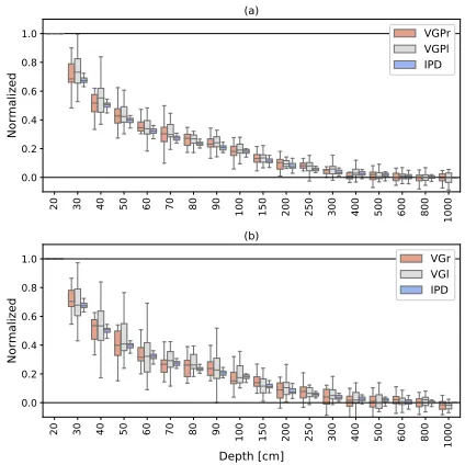
[image:5.612.332.545.88.208.2]Figure 6: Gain samples of the right eye of 2 participants ((a, c) P3 and (b, d) P6) at 4 different distances. The circles on each line represent the median of all samples within3◦windows.
figure, the peak of the VOR gain was not always at, or around, 20.3◦. We also observed the same linearity across head angles for the IPD samples, with no pronounced peak. The VOR gain obtained from our dataset varied across participants and was often not consistent with the theory (Figure 4). The VOR gain values were also sometimes lower than 1 indicating lower velocity for eye movements compared to the head in some trials which should not occur in pure VOR movements (we will discuss this more in the following subsections). Due to the instability of the VOR gain samples in each trial (see e.g., Figure 5.c), the median of all gain samples within the range of[−10◦,+10◦]was used as the final gain value for each distance. The mean of the IPD value within the same range was taken as the IPD value for each distance. Samples outside the interquartile range were considered as outliers and were excluded.
In order to be able to compare the VOR gain values between subjects, we normalised the gain and IPD curves by mapping the values into the range [0,1] where 1 corresponds to the values at D=20 cm as measured for each individual subject. The lower limit (0) for IPD corresponds to the value obtained at D=10 m. Since the VOR gain values were noisier than the vergence samples, we took more samples at far distances to define the lower limit for VOR gain and we took the average of gain values above 5 m. Note that there were no significant changes in the VOR and IPD samples at distances above 5 m. Figure 7.b shows the overall VOR gain and IPD samples collected from all subjects at different target distances. Despite the noise in the VOR signals, we can clearly see that monocular VOR gain and vergence change similarly across different target depths as the theory predicts.
5.2
VOR Gain using Pupil Centre
The raw pupil position data was less noisy than the gaze signal for some of the recordings. As suggested in [Mardanbegi et al. 2019], we also used pupil data instead of gaze data. Being able to use the pupil position makes the proposed method independent from gaze calibration. We used the velocity of the pupil centre instead of the angular velocity of the eyeball in our calculation of VOR gain:
20 30 40 50 60 70 80 90 100 150 020 250 300 400 500 600 800
10
00
0.0 0.2 0.4 0.6 0.8 1.0
No
rm
ali
ze
d
(a)
VGPr VGPl IPD
20 30 40 50 60 70 80 90 100 150 020 250 300 400 500 600 800
10
00
Depth [cm] 0.0
0.2 0.4 0.6 0.8 1.0
No
rm
ali
ze
d
(b)
[image:6.612.67.285.86.237.2]VGr VGl IPD
Figure 7: IPD values and VOR gain for each eye obtained at each fixation distance, showing (a) VGP measured using pupil centres, and (b) VG measured using gaze data.
V GP=dPC
dθH (6)
where PC is the centre of the pupil in the eye image. Strictly speak-ing, the VOR gain obtained from the pupil centre data (V GP) is not VOR gain and is not unitless, but it decreases similar to theV G
value as the target moves away from the eye. The pupil position is measured in pixels and its changes (as seen in the eye image) are nonlinear during eye rotations, however this nonlinearity is insignificant at small eye angles. TheV GPvalues obtained from the pupil centre data gave us more stable results and more consistency across participants at each depth compared toV Gvalues (Figure 7). We, therefore, used theV GPvalues in the rest of the paper.
6
GAZE DEPTH ESTIMATION
In this section, we investigate if VOR gain can be used for estimat-ing gaze fixation depth. The fixation depth is estimated when the user performs a head rotation (e.g., left/right head shake) whilst fix-ating on a fixed target. Ideally, gaze depth estimation is done using Eq.4 at a specific head angle (ideally at peak-gain angle) assuming that the radius of the rotation is constant, however as previously mentioned we use the median of gain samples in the range of±10◦ to compensate for gain instability. The general form of theV G
function for fixed head angle and radius is a rational function:
V G(D)= D
2+DP 0+P1
D2P2+DP3+P4 (7)
6.1
Data Pruning
The main assumption of the gaze depth estimation method is that the gain samples from each distance are taken during VOR with the gaze fixed on the target. To assess the gaze depth estimation method we excluded recordings where the gain values were likely to be invalid due to translational head shifts, fixation issues, etc. The IPD and gain signals are assumed to be very similar, therefore we took the median of the IPD signals across all subjects as our baseline to compare the VOR gain samples with. For each VOR gain curve, we calculated the sum of squares (SS) of the distance between the gain sample (Xд) and the baseline (Xb) at different target distances.
SS=
18
Õ
i=1
(Xдdi−Xbdi)
2 (8)
Wheredirefers to an individual target distance (18 distances in total). Any recording whereSS>thrwas considered as an outlier. The value for the thresholdthrwas set to 0.1 which gave us a good separation of the abnormal curves. Based on the above criteria, all recordings belonging to the subjects with fixation difficulties during the VOR (P5 & P7), as well as 14 out of 60 remaining record-ings (∼23%) were excluded. Potential reasons for these erroneous recordings are discussed in Section 7.
6.2
Depth Calibration
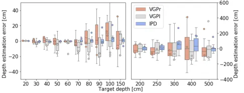
[image:7.612.321.556.85.185.2]In order to derive a model for gaze depth estimation, a number of VOR gain measurements need to be taken at different distances to estimate the unknown parameters of the model. To evaluate the gaze depth estimation in our study, we took all theV GPsamples collected at four distances (20,60,150,500 cm) to fit the model for every participant. The fitted model was then used to estimate the depth using the median of samples taken at every depth. Figure 8 shows the gaze depth estimation error (defined as the difference be-tween the estimated depth and actual depth) at different distances. The results show that the error using VOR gain increases propor-tionally to the fixation depth. The error from the vergence method was lower than the VOR method, in particular at distances below 2 meters. The result of the model fitting on the VGP samples (right eye) from a subject with a good recording (P3) is shown in Figure 9 and the gaze depth estimation error for this subject is also shown in Figure 8.
Figure 8: Gaze depth estimation error using Eq. 7. Samples at distances [20,60,150,500] cm are used for modelling and median samples at all distances used for testing.
0 200 400 600 800 1000
Target Depth [cm] 0.0
0.2 0.4 0.6 0.8 1.0 1.2
VG
Pr
Fitted model Raw samples
Figure 9: The VGPr samples (green curve) of a subject (P3) with very lowSS = 0.017(see Sec. 6.1) as an example of a good recording. The fitted model and the samples used for depth calibration are shown in red.
6.3
Generic Model
We further investigated the possibility of using a generic model for gaze depth estimation, since both the theory and our empirical data show that vergence and VOR gain curves against depth are almost identical (Figure 7). The ability to use a generic model decreases the number of calibration points required for gaze depth estimation.
We took the average of the coefficients obtained from fitting the model using Eq. 7 to all normalised IPD and VGP curves collected from all subjects (except those recording that were excluded) and used that fixed generic model for gaze depth estimation. The generic model (S) obtained from all the subjects was:
S(D)= D
2+0.66∗D+100
0.06∗D2+3.2∗D+25.96 (9)
Since the generic model relies on normalised samples, it requires the IPD or VGP measures obtained from the subject to be normalised before using the model. For this, the upper and lower bounds of the IPD or VGP must be found which requires taking samples at two different distances, one at 20 cm, and one above 500 cm for which the generic model is made.
[image:7.612.54.297.568.661.2]To test the performance of the model for gaze depth estimation, we normalised the gain values obtained from each recording sam-ples taken from 20 cm and 10 m and then solved the equation above for samples taken from all distances. The results are shown in Fig-ure 10 and suggest that for distances below 3 m, the accuracy of the
generic model for gaze depth estimation is close to the accuracy of the normal calibration using four distances.
7
DISCUSSION
Our results show that fixation depth can be recovered from VOR gain of a single eye, with a similar response to using binocular ver-gence. We have shown that gaze depth estimation can be achieved using regression models of VOR gain by fitting a model per par-ticipant based on four calibration depth estimates. Additionally, a generic model can be used across users, thus requiring only two depth estimates to establish upper and lower boundaries for nor-malisation. In contrast to other gaze depth estimation techniques, VOR-based gaze depth estimation is a non-continuous process, re-quiring head movements to trigger the gaze depth estimation. The gaze depth estimation error using VOR gain increases proportion-ally to the fixation depth, suggesting that this technique may not be appropriate for accurate gaze depth estimation. However, as shown in previous work this is a compelling mechanism for target disambiguation in 3D environments, where objects may be par-tially occluded at different distances, and when combined with head gestures for selection [Mardanbegi et al. 2012, 2019; Nukari-nen et al. 2016]. Unlike vergence-based methods, the VOR method using pupil centre is not reliant on gaze calibration and therefore does not suffer gaze calibration drift which is a common issue in many commercial eye trackers.
Compared to previous methods of gaze depth estimation, extrac-tion of the signals required to calculate VOR gain does not rely on camera-based systems. The required eye velocity signals can also be measured using electrooculography (EOG) signals, whereas head velocities can be calculated using cheap inertial measurement units which are prolific in many HMDs. Beyond virtual reality, VOR-based gaze depth estimation is also applicable for applications in mixed or augmented realities, either as target disambiguation during selection or to adapt display rendering non-continuously.
Our results show that the measured VOR gain is unexpectedly noisier than the vergence response. Causes of this noise are un-clear and may be specific to our setup, signal processing, or several factors that affect the VOR gain which we disregarded in our im-plementation. Factors that could contribute to the noise include:
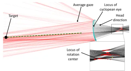
Inconsistent radius of rotation: While the vertebral column is
the centre of rotation for a pure horizontal head rotations, the location of the centre could vary during natural head rotations. We investigated the head rotations in our experiment to see whether the centre of rotation (pointOin Figure 2) remains fixed during natural and self-generated horizontal head rotations. This was assessed by intersecting the consecutive head rays (black lines in Figure 11). The locus of this intersection point, which represents the centre of rotation was not perfectly fixed in any of the trials (see Figure 11). As a result, the VOR movements were not ideal and head rotations were often combined with head translation and torso rotation.
[image:8.612.331.543.80.195.2]The average distance between the midpoint of two eyes and the centre of rotation at the beginning of each trial was taken as the radius for each trial. The average radius of our participants was 6.17 cm (SD=0.86, min=4.8, max=7.3). This value is much smaller than the average distance between the vertebral column and cyclopean eye that we referred to in our theoretical discussion.
Figure 11: Top view of an example trial (P5, D=20 cm), show-ing gaze and head rays durshow-ing head rotation.
Gaze on target: Some of our participants found it difficult to
maintain their gaze on the target during head rotations (see e.g., Figure 11. Although we excluded those frames where the gaze angle for the target was above 4◦, the gaze may still be in motion (e.g., passing through the target) which would influence the eye velocity measured, and hence the VOR gain. The misalignment between the two velocity signals in Figure 5 suggests either lag between the eye and head movements during VOR [Hine and Thorn 1987], poor synchronisation between the head and eye signals, or non-VOR eye movements that affect the eye velocity. These invalidate the key assumption of the proposed method, and could lead to miscellaneous readings of the VOR gain.
Rotational vs Translational VOR: .Some participants performed
translational movement during head rotations, either towards or in the opposite direction of the rotation (e.g., moving the neck to the left or right whilst rotating the head to the right). This could be one source of instability of the VOR gain (and gain values below unity) and could have also contributed to the phase difference between head and eye velocity signals that was visible in the majority of the trials.
8
CONCLUSION
This work has analysed the possibility of using VOR gain for es-timating gaze depth using data from one eye as an alternative to binocular methods, such as vergence. Using a theoretical model, we have discussed how target distance and anthropometry affect the VOR gain. Using empirical data acquired from a virtual reality headset, we compared our theoretical understanding of VOR gain to real-world data. Furthermore, we demonstrated how regression models can be used to estimate fixation depths based on eye and head velocities alone. We also discussed the limitations of using VOR gain for gaze depth estimation, and elaborated on possible causes of error that could be improved upon in future work. Using VOR gain for gaze depth estimation is compelling due to the flex-ibility of sensing configurations that can be used to measure the required signals, whilst only requiring data from one eye at a time.
ACKNOWLEDGMENTS
REFERENCES
Florian Alt, Stefan Schneegass, Jonas Auda, Rufat Rzayev, and Nora Broy. 2014a. Using Eye-tracking to Support Interaction with Layered 3D Interfaces on Stereoscopic Displays. InProceedings of the 19th International Conference on Intelligent User Interfaces (IUI ’14). ACM, New York, NY, USA, 267–272.DOI:http://dx.doi.org/10. 1145/2557500.2557518
Florian Alt, Stefan Schneegass, Jonas Auda, Rufat Rzayev, and Nora Broy. 2014b. Using Eye-tracking to Support Interaction with Layered 3D Interfaces on Stereoscopic Displays. InProceedings of the 19th International Conference on Intelligent User Interfaces (IUI ’14). ACM, New York, NY, USA, 267–272.DOI:http://dx.doi.org/10. 1145/2557500.2557518
Dora E Angelaki. 2004. Eyes on target: what neurons must do for the vestibuloocular reflex during linear motion.Journal of neurophysiology92, 1 (2004), 20–35. B. Biguer and C. Prablanc. 1981. Modulation of the vestibulo-ocular reflex in eye-head
orientation as a function of target distance in man.Progress in Oculomotor Research (1981). https://ci.nii.ac.jp/naid/10008955589/en/
Gilles Clément and Fernanda Maciel. 2004. Adjustment of the vestibulo-ocular reflex gain as a function of perceived target distance in humans.Neuroscience letters366, 2 (2004), 115–119.
Han Collewijn and Jeroen BJ Smeets. 2000. Early components of the human vestibulo-ocular response to head rotation: latency and gain.Journal of Neurophysiology84, 1 (2000), 376–389.
Nathan Cournia, John D Smith, and Andrew T Duchowski. 2003. Gaze-vs. hand-based pointing in virtual environments. InCHI’03 extended abstracts on Human factors in computing systems. ACM, 772–773.
Brian C. Daugherty, Andrew T. Duchowski, Donald H. House, and Celambarasan Ramasamy. 2010. Measuring Vergence over Stereoscopic Video with a Remote Eye Tracker. InProceedings of the 2010 Symposium on Eye-Tracking Research and Applications (ETRA ’10). ACM, New York, NY, USA, 97–100.DOI:http://dx.doi.org/ 10.1145/1743666.1743690
S. Deng, J. Chang, S. Hu, and J. J. Zhang. 2017. Gaze Modulated Disambiguation Technique for Gesture Control in 3D Virtual Objects Selection. In2017 3rd IEEE International Conference on Cybernetics (CYBCONF). 1–8.DOI:http://dx.doi.org/10. 1109/CYBConf.2017.7985779
Andrew T. Duchowski, Donald H. House, Jordan Gestring, Robert Congdon, Lech Świrski, Neil A. Dodgson, Krzysztof Krejtz, and Izabela Krejtz. 2014. Comparing Estimated Gaze Depth in Virtual and Physical Environments. InProceedings of the Symposium on Eye Tracking Research and Applications (ETRA ’14). ACM, New York, NY, USA, 103–110.DOI:http://dx.doi.org/10.1145/2578153.2578168
Andrew T. Duchowski, Eric Medlin, Anand Gramopadhye, Brian Melloy, and Santosh Nair. 2001. Binocular Eye Tracking in VR for Visual Inspection Training. In Pro-ceedings of the ACM Symposium on Virtual Reality Software and Technology (VRST ’01). ACM, New York, NY, USA, 1–8.DOI:http://dx.doi.org/10.1145/505008.505010 Andrew T. Duchowski, Brandon Pelfrey, Donald H. House, and Rui Wang. 2011.
Measuring Gaze Depth with an Eye Tracker During Stereoscopic Display. In Proceedings of the ACM SIGGRAPH Symposium on Applied Perception in Graph-ics and Visualization (APGV ’11). ACM, New York, NY, USA, 15–22. DOI:http: //dx.doi.org/10.1145/2077451.2077454
Peter A Gorry. 1990. General least-squares smoothing and differentiation by the convolution (Savitzky-Golay) method.Analytical Chemistry62, 6 (1990), 570–573. Esteban Gutierrez Mlot, Hamed Bahmani, Siegfried Wahl, and Enkelejda Kasneci. 2016.
3D Gaze Estimation Using Eye Vergence. InProceedings of the International Joint Conference on Biomedical Engineering Systems and Technologies (BIOSTEC 2016). SCITEPRESS - Science and Technology Publications, Lda, Portugal, 125–131.DOI: http://dx.doi.org/10.5220/0005821201250131
C. Hennessey* and P. Lawrence. 2009. Noncontact Binocular Eye-Gaze Tracking for Point-of-Gaze Estimation in Three Dimensions.IEEE Transactions on Biomedical Engineering56, 3 (March 2009), 790–799.DOI:http://dx.doi.org/10.1109/TBME.2008. 2005943
Trevor Hine and Frank Thorn. 1987. Compensatory eye movements during active head rotation for near targets: effects of imagination, rapid head oscillation and
vergence.Vision research27, 9 (1987), 1639–1657.
J. Ki and Y. Kwon. 2008. 3D Gaze Estimation and Interaction. In2008 3DTV Conference: The True Vision - Capture, Transmission and Display of 3D Video. 373–376. DOI: http://dx.doi.org/10.1109/3DTV.2008.4547886
Yong-Moo Kwon, Kyeong-Won Jeon, Jeongseok Ki, Qonita M Shahab, Sangwoo Jo, and Sung-Kyu Kim. 2006. 3D Gaze Estimation and Interaction to Stereo Dispaly.IJVR 5, 3 (2006), 41–45.
Radosław Mantiuk, Bartosz Bazyluk, and Anna Tomaszewska. 2011. Gaze-Dependent Depth-of-Field Effect Rendering in Virtual Environments. InSerious Games De-velopment and Applications, Minhua Ma, Manuel Fradinho Oliveira, and João Madeiras Pereira (Eds.). Springer Berlin Heidelberg, Berlin, Heidelberg, 1–12. Diako Mardanbegi, Dan Witzner Hansen, and Thomas Pederson. 2012. Eye-based
Head Gestures. InProceedings of the Symposium on Eye Tracking Research and Applications (ETRA ’12). ACM, New York, NY, USA, 139–146. DOI:http://dx.doi. org/10.1145/2168556.2168578
Diako Mardanbegi, Tobias Langlotz, and Hans Gellersen. 2019. Resolving Target Ambi-guity in 3D Gaze Interaction through VOR Depth Estimation. InCHI’19 Proceedings on Human Factors in Computing Systems.
Olivier Mercier, Yusufu Sulai, Kevin Mackenzie, Marina Zannoli, James Hillis, Derek Nowrouzezahrai, and Douglas Lanman. 2017. Fast Gaze-contingent Optimal De-compositions for Multifocal Displays.ACM Trans. Graph.36, 6, Article 237 (Nov. 2017), 15 pages.DOI:http://dx.doi.org/10.1145/3130800.3130846
Susan M. Munn and Jeff B. Pelz. 2008. 3D Point-of-regard, Position and Head Orienta-tion from a Portable Monocular Video-based Eye Tracker. InProceedings of the 2008 Symposium on Eye Tracking Research & Applications (ETRA ’08). ACM, New York, NY, USA, 181–188. DOI:http://dx.doi.org/10.1145/1344471.1344517 Tomi Nukarinen, Jari Kangas, Oleg Špakov, Poika Isokoski, Deepak Akkil, Jussi Rantala,
and Roope Raisamo. 2016. Evaluation of HeadTurn: An Interaction Technique Using the Gaze and Head Turns. InProceedings of the 9th Nordic Conference on Human-Computer Interaction (NordiCHI ’16). ACM, New York, NY, USA, Article 43, 8 pages. DOI:http://dx.doi.org/10.1145/2971485.2971490
Jason Orlosky, Takumi Toyama, Daniel Sonntag, and Kiyoshi Kiyokawa. 2016. The Role of Focus in Advanced Visual Interfaces.KI - Künstliche Intelligenz30, 3 (01 Oct 2016), 301–310.DOI:http://dx.doi.org/10.1007/s13218-015-0411-y Gary D Paige. 1989. The influence of target distance on eye movement responses
during vertical linear motion.Experimental Brain Research77, 3 (1989), 585–593. Thies Pfeiffer, Marc Erich Latoschik, and Ipke Wachsmuth. 2008. Evaluation of
binocu-lar eye trackers and algorithms for 3D gaze interaction in virtual reality environ-ments.JVRB-Journal of Virtual Reality and Broadcasting5, 16 (2008).
A Poston. 2000. Static adult human physical characteristics of the adult head. Depart-ment of Defense Human Factors Engineering Technical Advisory Group (DOD-HDBK-743A) pp72 (2000), 75.
Mina Ranjbaran and Henrietta L Galiana. 2012. The horizontal angular vestibulo-ocular reflex: a non-linear mechanism for context-dependent responses. In2012 Annual International Conference of the IEEE Engineering in Medicine and Biology Society. IEEE, 3866–3869.
Gerald FÃČÅŠtterer Norbert Leister Stephan Reichelt, Ralf HÃČâĆňussler. 2010. Depth cues in human visual perception and their realization in 3D displays. (2010).DOI: http://dx.doi.org/10.1117/12.850094
Vildan Tanriverdi and Robert JK Jacob. 2000. Interacting with eye movements in virtual environments. InProceedings of the SIGCHI conference on Human Factors in Computing Systems. ACM, 265–272.
E Viirre, D Tweed, K Milner, and T Vilis. 1986. A reexamination of the gain of the vestibuloocular reflex.Journal of Neurophysiology56, 2 (1986), 439–450. Rui I. Wang, Brandon Pelfrey, Andrew T. Duchowski, and Donald H. House. 2014.
Online 3D Gaze Localization on Stereoscopic Displays.ACM Trans. Appl. Percept. 11, 1, Article 3 (April 2014), 21 pages.DOI:http://dx.doi.org/10.1145/2593689 Martin Weier, Thorsten Roth, André Hinkenjann, and Philipp Slusallek. 2018.