Study of Response of Wall Type Pier for Varying Width of
Superstructure by Response Spectrum Method
Ratnakar R. Karde
1, Dr. P. D. Kumbhar
21
M. Tech. student, Dept. of Civil-structural Engineering, RIT, Maharashtra, India
2
Head of Dept. of Civil Engineering¸ RIT, Maharashtra, India
---***---Abstract -
Bridges are key elements of the infrastructure. Itis an essential economical and social interest to protect and maintain them. Seismic forces damages bridge structures in a large scale so, it is important to protect structure from seismic loading. In this paper Seismic analysis of wall type pier is carried out by varying the width of superstructure (8m, 10m, 12.5m, and 16m). Work is carried out by using finite element-based software (MIDAS Civil). By keeping material properties and support conditions constant. FEM models of piers are developed for all the widths of superstructures. Analysis of models are done by considering self-weight of pier and loading from superstructure (by IRC 70R and IRC Class A) by taking into account seismic zone IV as per IRC and Is 1893-2016. Response spectrum analysis method has been used for the analysis. For the analysis two response functions are developed namely Rs-X and Rs-Y. Responses in terms of bending stresses, natural period and modal mass participation are determined for pier structures. For all the width of bridge superstructures (8m, 10m, 12.5m and 16m) comparative study is carried out.
Key Words: Wall type pier, Seismic analysis, stresses, finite
element analysis, Response Spectrum Analysis.
1. INTRODUCTION
A pier is a raised structure of bridge typically supported by widely spread piles or pillars. Piers are an integral part of the load path between the superstructure and the foundation. Piers are the element which resists the vertical loads from the superstructure as well as the horizontal loads not resisted by the abutments. A multi-span bridge requires piers to support the ends of spans between these abutments. Piers are important components of a bridge structure and a particular type of pier is selected by taking into account the site condition, geometrical requirements and the location of the pier. By changing the location condition, the selection of pier and shape of pier can change for demand of the situation. The bridge substructures or piers are provided with different cross-sectional shapes such as circular, rectangular, oval etc.
A large portion of India is prone to damaging levels of seismic hazards. Hence, it is necessary to take in to account the seismic load for the design of bridge structures. The lateral load induced due to wind and especially due to earthquake ground motion, the resisting systems used in bridge structure is bridge pier. In bridge structure the
lateral loads due to earthquake are a matter of concern. These lateral forces can produce critical stresses in the structure, induce undesirable stresses in the structure, induce undesirable vibrations or cause excessive lateral sway of the structure.
With ground motion the risk associated with the bridge structure increases, especially under severe earthquake forces, dynamic analysis of bridge structure is important to be carried out, it becomes necessary to give special attention in the process of its analysis and design.
In the present paper, analysis of wall type pier by considering the various widths of superstructure is carried out by Response spectrum method under dynamic load cases as per IRC 6:2016 using FEM based software (MIDAS Civil).
1.1 Response Spectrum Method
The response spectrum represents an envelope of upper bound responses, based on several different ground motion records. For the purpose of seismic analysis as per IS: 1893 (Part 1): 2016 is used. This spectrum is based on strong motion records of Indian earthquakes. This method is an elastic dynamic analysis approach that relies on the assumption that dynamic response of the structure may be found by considering the independent response of each natural mode of vibration and then combining the response of each in same way. This is advantageous in the fact that generally only few of the lowest modes of vibration have significance while calculating moments, shear and deflections at different levels of the building.
2. CROSS SECTIONAL PROPERTIES OF THE PIER
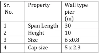
The analysis work is carried out for wall type piers. The basic geometrical dimensions of the piers under consideration are as indicated in Table 1. Cross-sectional properties of the wall type pier are considered here with pier cap. Fixation of the dimensional properties are considered by practice.
Table -1: Basic geometrical dimensions of the piers
Sr.
No. Property Wall type pier (m) 1 Span Length 30
2 Height 10
3 Size 6 x0.8
4 Cap size 5 x 2.3
The modelling of the bridge substructure (pier) is carried out using FEM based MIDAS Civil software considering the basic dimensions of the bridge substructure indicated in Table 1.
The models are developed for different widths of bridge superstructure of pier. Total four models are developed of pier by varying the width of superstructure (8m, 10m, 12.5m and 16m) keeping same material properties and boundary conditions. For more accuracy in results, pier is divided in parts of 1m with nodding the elements. The modelling done for of each type of pier is presented in the following sections.
3. MODELLING OF WALL TYPE PIER
The modelling of wall type of pier is done by varying the width of superstructure from 8m to 16m (8m, 10m, 12.5m, and 16m) based on lane rules of IRC 5 and the keeping its height constant (10m).The dimensions of various components of wall type pier considered with different types superstructures for developing the models are given in Table 2.
Table -2: Model Details of wall type pier
Sr. No.
Width of Super- Structure (m)
Height of Pier (m)
Width of Pier cap (m)
Pier Dime-nsions (m)
Pier Cap
Dimensions (m)
1 8 10 6 5x0.8 1.2x2.3x6
2 10 10 7 6x0.8 1.2x2.3x7
3 12.5 10 9 8x0.8 1.2x2.3x9
4 16 10 11 10x0.8 1x2.3x11
The typical model developed for 8m width of superstructure is shown in Fig. 1 similarly models for different widths namely 10m, 12.5m and 16m width of superstructure are developed for the analysis.
For wall type pier solid track and for pier cap solid rectangular section is used for modelling
Fig -1: Finite element model of wall type pier
4. ANALYSIS OF STRUCTURE
In this section response spectrum analysis of structure are described.
4.1 Material Properties
[image:2.595.74.248.121.214.2]The material properties for development of all the models are kept constant. The details of which are given in Table 3.
Table- 3: Material Properties
Sr. No. Material property Value
1 Grade of Concrete M50
2 Characteristics Strength
(Fck) 50MPa
3 Young's Modulus
(Ec) 3.5535e˄7 kN/m2
4 Density of Concrete 23.6 kN/m3
5 Grade of Steel Fe 500
6 Poisson’s Ratio 0.2
7 Coefficient of Thermal
Expansion 1.853e˄-4 1/C
8 Damping ratio 0.05
The time dependent properties such as creep, shrinkage and compressive strength are also considered for all the models. All the properties mentioned are calculated for normal type of cement.
4.2 Loading Considerations
[image:2.595.304.561.407.662.2]Dead load of superstructure consists of self-weight of girder, dead load of wearing coat (i.e. over girder) and dead load of crash barrier. Live loads include moving load and breaking force. All these loads are considered for the analysis of superstructure and then reactions on bearing are determined. The reactions per bearing are used as point loads on the piers.
[image:3.595.329.540.132.224.2]Wind load on the substructure is determined as per the specifications given in IRC-6 (2016) Code of practice for Road bridges (section: ii Loads and load combinations, Clause 209.4).
Table- 4: Load Considered
Sr. No.
Width of superstructure (m)
Load from superstructure
(kN)
Wind load (kN)
1 8 2000 46
2 10 2400 48
3 12.5 2600 50
4 16 3000 52
4.3 Parameters Considered in Analysis
For the response spectrum analysis purpose following parameters are considered.
4.3.1 Support Condition
By restraining all 3-translation degrees of freedom, fixed support is modeled for all types of structures considered.
4.3.2 Bearing Locations
[image:3.595.314.518.358.444.2]The elastomeric type of bearings with 800 x 800mm size are considered for the purpose of transmitting the loads from superstructure. The number of bearings and their locations are decided based on the width of girder. Fig. 2 shows the total no. of bearings and their spacings in the along the span and across the width of the bridge structure.
Fig -2: Bearing Locations
4.3.3 Elastic Links
To transfer the effect of loading successfully to the support from the pier cap node to the pier column node, without any loss in property, the rigid types of elastic links are provided in between connective points of pier and pier cap as shown in Fig.3. Also, the nodes of bearing locations are connected to
their respective parent nodes with the help of rigid type of elastic links (Fig. 3).
Fig -3: Rigid type of elastic links
4.3.4 Response Spectrum
The design spectrum used is of medium soil as per IS 1893 Part I (2002). A response spectrum is shown in figure 4. design acceleration coefficient (Sa/g) versus time is
[image:3.595.56.265.607.667.2]presented in figure corresponding to 5% damping. In this study for response spectrum analysis 4 modes are considered for each structure and results are obtained with respect to the nodes considered.
Fig -4: Response spectrum for soil as per IS 1893-2016 Part I
5. RESULTS AND DISCUSSION
The results of Response spectrum analysis obtained by using MIDAS Civil software for the responses namely bending stresses, Time period and modal mass participation are discussed in the following section.
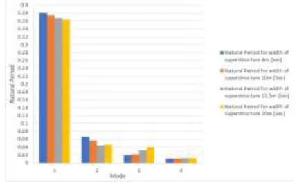
5.1 Natural Period
The observed variation in time period values of wall type piers for various widths of superstructure are plotted as shown in Fig. 5.
[image:3.595.338.553.630.772.2]From Fig. 5, it is observed that the natural period of wall type pier decreases with increasing width of superstructure for first and second mode. But for third and fourth mode the values of natural period increases with increase in width of superstructure. Total decrease of 4.35% and 30.23% was observed for first and second mode respectively, for 8m to 16m varying width of superstructure. Whereas increase of 50.74% and 12.88% was observed in third and fourth mode respectively.
5.2 Modal Mass Participation
[image:4.595.68.256.273.400.2]The obtained maximum modal mass participation (Z direction) values for various widths of superstructure of wall type piers are shown in Fig. 6.
Fig -6: Modal Mass participation
From Fig. 6, it is observed that the values of modal mass participation have no significant change for increase in width of superstructure. Average decrease in modal mass participation with increase in width of superstructure (8m to 16m) is found to be 1.988% and average participation is found to be 89.43%.
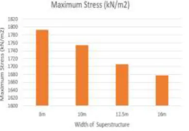
5.3 Stress
The stress values observed for various widths of superstructure of wall type piers are shown in Fig. 7.
Fig -7: Maximum Stress
From Fig. 7, it is observed that the values of maximum stresses decrease with increasing width of superstructure. Percentage decrease in the maximum stress is 6.46%.
5. CONCLUSIONS
From the results of response spectrum analysis of wall type pier by varying width of superstructure, following conclusions are drawn:
i. Constant decrease in values of natural period was observed for first and second mode for all width models by 4.35% and 30.23% respectively.
ii. Slight increase in natural period was obtained for third mode i.e. 50.74%. No significant change was obtained for fourth mode.
iii. No considerable change in modal mass participation was found, but it decreases with increase in width of superstructure. Average decease in modal mass participation is 1.988%.
iv. Linear decrement in maximum stresses was observed with increase in width of superstructure. Percentage decrease was found to be 6.46% in maximum stress values from 8m to 16m.
REFERENCES
[1] Amit Katkar, P. M. Kulkarni, “Parametric Study of
Bridge Piers”, IRJET, (2018), Vol. 05, pp-656-660.
[2] Ching-Jong Wang, “Performance-Based Design for a
Tall-Pier Bridge Prototype in Massive Earthquakes”, Journal of performance of constructed facilities, 10.1061/(ASCE)CF.19435509.0000359(2013).
[3] Helidon Kokona, Enkeleda Kokona, “Impact of pier
length and connection type in static and dynamic response of RC bridge structure”, 3rd International Balkans Conference on Challenges of Civil Engineering, 3-BCCCE, 19-21 May 2016, Epoka University, Tirana, Albania, pp-492-503.
[4] IRC – 6, “Standard Specifications and Code of Practice
for Road Bridges (Loads and Stresses)”.
[5] IRC – 112, “Code of Practice for Concrete Road Bridges
(Design)”.
[6] IRC SP – 114, “Standard Specifications and Code of
Practice for Road Bridges (Seismic Specifications for Design)”.
[7] IS 1893 Part I, “Criteria for Earthquake Resistant
Design of Structures”.
[8] Joao Coimbra Sampayo,Carlos Sousa Oliveiral, “Seismic
Performance of Bridge with different pier Heights. Longitudinal analysis of an existing bridge”, 9th International Conference on Structural Dynamics, EURODYN, (2014).
[9] Kubilay Kaptan, “Non-Linear Analysis of Bridge
Structures”, Trakya University Journal of Engineering Sciences, (2017), pp-17-30.
[10] Qingxiang Zheng Wenhua Liu, “Seismic Design of High
Piers for Mountain Bridges”,ARPN, (2005), Vol. 05, pp-58-63.
[11] R. K. Dowell, “Nonlinear Time-History Seismic Analysis
of Bridge Frame Structure”, 15 WCEE Lisboa (2012).
[12] R NP Singh, Hemant Kumar Vinayak, “Seismic Bridge
Pier Analysis for Pile Foundation by
[13] Force and Displacement Based Approaches”, FACTA
[image:4.595.75.270.558.693.2][14] Robert K. Dowell, “Super-fast Nonlinear Time-History
Seismic Analysis of Bridge Frame Structure”, 9th International Conference on Structural Dynamics, EURODYN, (2014), pp-1125-1132.
[15] S. K. Duggal, “Earthquake resistant design of
structures”, Oxford publication, (2013).
[16] Sun Zhi-guo,LI Xiao-li “Seismic Design of Bridges with
Short Pier in High Earthquake Intensity Zones”, ASCE,(2013), VOL. 7, pp-50-55.
[17] Yudong Mao, Robert Thremblay et al. “New Simplified