© 2019, IRJET | Impact Factor value: 7.34 | ISO 9001:2008 Certified Journal | Page 653
Modified Perturb and Observe MPPT Algorithm for Drift Avoidance
using SEPIC Converter
Mr. Yogesh Y. Katdare
1, Mrs. Pranita Chavan
2, Mr. Dhananjay Borse
31Assistant Professor, VPM’s MPCOE, Velneshwar
2Assistant Professor and HOD, Pillai HOC College of Engineering, Rasayani, Panvel
3R&D Department, Radium Engineering, Bavdhan, Pune
---***---Abstract -
MPPT (Maximum Power Point Tracking) is a commonly used technique for extracting maximum possible power from solar photovoltaic (PV) systems under all conditions. Out of various methods used for achieving MPPT, perturb and observe (P&O) is very popular and widely accepted method owing to its simple nature, ease in implementation and high efficiency. However, P&O algorithm has drawback that it suffers from drift phenomenon. Which results in drifting away of algorithm from maximum power point during sudden change in atmospheric conditions. Therefore it becomes essential to do modifications in traditional P&O algorithm for drift avoidance. The new algorithm which thus implemented is termed as ‘Modified P&O Algorithm’ which takes change in current, voltage and power into consideration. This new algorithm is verified using MATLAB/Simulink. SEPIC converter is used for controlling DC to DC power flow by controlling output (load) voltage. Results are tested on simulation as well as hardware setup. Results prove that modified P&O algorithm is drift free algorithm and it can track maximum power point under any changing atmospheric condition.Key Words: Maximum Power Point Tracking (MPPT), Per-turb and Observe (P&O), PV, drift phenomenon, SEPIC Con-verter, MATLAB/Simulink
1. INTRODUCTION
Because of clean nature solar energy does not produce any environmental hazardous emissions. It is very widely available in India as well as in the world. These are some positive points of solar energy. But as far as its utilization for Electrical power generation is concerned, its fluctuating nature due to different atmospheric conditions is a major issue. Because of this, efficiency of gaining Electrical energy from solar energy (converting solar energy into electrical energy) affects drastically.
Maximum Power Point Tracking is a systematic approach which takes efficiency of solar PV system as a highest priority task into consideration. Various algorithms have been put forward to achieve this. Out of these various algorithms, ‘Perturb & Observe’ MPPT algorithm became most popular owing to its simplicity, superiority, ease in implementation etc. It is very efficient in nature. The principle of its working is, perturbation of voltage and power in any direction in such a way that operating point should follow the direction where power drawn from PV system is maximum. Reduction in the power output by perturbation is also possible in the similar way. Simply speaking it is an algorithm which keeps system oscillating very near to maximum power point (MPP). [1] – [8]
Drawback of this algorithm is that changing atmospheric conditions badly affects its performance which is the main cause of ‘drift,’ due to which maximum power point tracking cannot be properly achieved, which in turn results into decrement in efficiency. This paper presents modification in conventional P&O algorithm by including change in current into loop (dI) which gives rise to new algorithm, i.e. ‘Modified P&O Algorithm.’ Drift avoidance is possible by modified P&O algorithm. This paper mainly focuses on SEPIC converter design and ratings of its components for hardware in section II. Section III describes traditional Perturb & Observe Algorithm along with flowchart. Section IV covers modified Perturb & Observe Algorithm along with its drift free nature. Simulation model & experimental hardware set up along with results are discussed in section V. Paper is concluded in section VI.
2. SEPIC converter & its components ratings
© 2019, IRJET | Impact Factor value: 7.34 | ISO 9001:2008 Certified Journal | Page 654 Above fig. 1 shows circuit diagram of SEPIC converter. SEPIC means Single-ended primary-inductor converter which is basically a dc to dc converter. It can either step up or step down the output voltage than input voltage. This can be achieved by adjusting ‘duty cycle’ of switching device of SEPIC converter. Generally MOSFET or Transistor can be used as a switching device of SEPIC converter. [9].
Somehow it is similar to buck-boost converter. But it has certain advantages so that it is selected. Some advantages of SEPIC converter are summarized here,
a) It is more unforgiving than boost, or buck-boost converter, because MOSFET & diode voltage and currents are higher
b) Energy storage components are more
c) Load current is carried by capacitors as well as source which is not possible in buck boost converter d) Permits easy isolation
Output voltage in terms of input voltage for SEPIC converter is as given below,
Vout = D.Vin / (1 – D) (1) Where D is duty cycle.
Worst case Ripple voltage is given by,
ΔV = ΔQ/C = Iout / Cf (2)
Average input voltage equation is given by,
VIN = VL1 + VC1 + VL2 (3)
And current Equation is given by,
ID1 = IL1-IL2 (4)
For building hardware, values of SEPIC converter components are summarized in following table
Table 1 SEPIC design
Converter type Input inductor current Output capacitor voltage Output capacitor
current Diode and MOSFET voltage
Diode and MOSFET
current
Buck/Boost 9A 250V 5.66A p-p 200V, 250V 16A, 20A
Considering Worst case SEPIC situation
10A 90V 10A, 5A 40V, 90V 10A, 5A
Inductor L1 & L2. 100 micro henry, 9A
Capacitor C. 1500 micro farad, 250V, 5.66A p-p Diode D. 200V, 16A
MOSFET M. 250V, 20A
© 2019, IRJET | Impact Factor value: 7.34 | ISO 9001:2008 Certified Journal | Page 655 Fig. 2 SEPIC converter hardware on PCB
3. TRADITIONAL PERTURB AND OBSERVE MPPT ALGORITHM
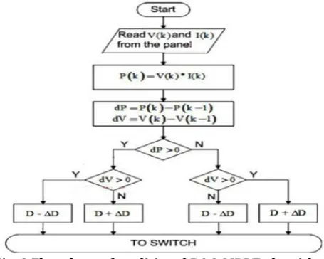
P&O algorithm is a very popular and advantageous MPPT technique [1] - [5]. It requires very less number of parameters for operation. It is having very simple structure. Following Fig. 3 shows conventional P&O algorithm flowchart.
Fig. 3 Flowchart of traditional P&O MPPT algorithm
Terminal voltage of PV array is perturbed periodically and compared with PV output power of previous cycle. ΔD get added or subtracted from the duty cycle depending on whether PV power and voltage has increased or decreased in that given time so as to achieve MPP point.
A. Three Levels of Steady State Operation
© 2019, IRJET | Impact Factor value: 7.34 | ISO 9001:2008 Certified Journal | Page 656 Fig. 4 steady state condition three level operation
B. Occurrence of Drift
Increment in insolation is the main reason for becoming Drift dominant. This is main drawback of traditional P&O algorithm. Because of this, algorithm not able to achieve maximum Power Point, as it becomes unsuccessful in choosing proper maximum power point, but chooses wrong operating point. Because of all this, the overall efficiency in the system decreases and system losses increase. Fig. 5 focuses on occurrence of Drift.
Fig. 5 occurrence of drift
Because of wrong interpretation about increment in power (dP > 0) it becomes difficult to confirm whether it is due to insolation or perturbation. If insolation increases when operating point is at 1, Algorithm decides new operating point at 4 which is on new insolation curve. At this point change in power and change in voltage both are positive. So that duty cycle will be reduced and again new operating point gets shifted to point 5. This point 5 is not MPP, but far away from it. This phenomenon in which operating point shifts away from maximum power point is called as a drift.
IV MODIFIED P&O MPPT Algorithm with Drift Avoidance
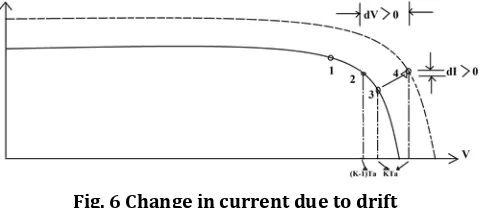
Inclusion of change in current (dI) into the algorithm can eliminate the Drift problem. Such modification of this additional (dI) component in traditional P&O algorithm gives rise to new algorithm which is called as ‘Modified Perturb and Observe’ MPPT algorithm. This new algorithm can give drift free operation. Apart from that, it possesses almost all advantages of traditional P&O algorithm. In this case, new operating point can be identify by PV module I-V characteristics shown in fig. 6
Fig. 6 Change in current due to drift
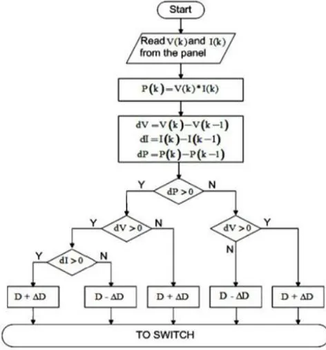
[image:4.595.180.421.618.722.2]© 2019, IRJET | Impact Factor value: 7.34 | ISO 9001:2008 Certified Journal | Page 657 achieve operating point as closer as possible to Maximum Power Point, if ΔV and dI used together for drift elimination. Fig. 7 shows flowchart for this drift free modified perturb and observe algorithm. This algorithm eliminates problem of drift by incorporating dI. From fig. 8 & 9 it is clear that this algorithm gives drift free operation.
[image:5.595.170.429.626.734.2]Fig. 7 Flowchart of modified P&O algorithm
Fig. 8 P-V characteristics for drift free modified P&O algorithm during one time increase in insolation
© 2019, IRJET | Impact Factor value: 7.34 | ISO 9001:2008 Certified Journal | Page 658 V. SIMULATION & HARDWARE RESULTS
A. Simulation
The circuit model is used to design PV module for simulation study. Parameters of the module are:
Series Resistance Rs=0.2300 ohm, Parallel Resistance Rp = 45 ohm, number of panels in series = 50, number of panels in parallel = 5 and total power output of module = 7.5kW. The values of components used for SEPIC converter are: L1 = 180 H, L2 = 180 H, C1 = 47 F, C2 = 3300 F, fs = 5kHz and RLoad = 47 ohms.
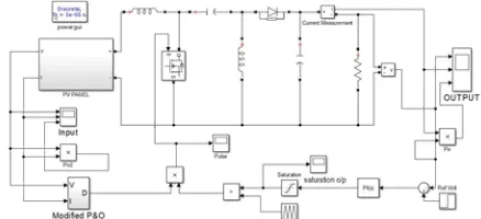
[image:6.595.186.405.237.337.2]MATLAB/Simulink model of the proposed system is shown in Fig. 10 and the design of proposed P&O subsystem is shown in Fig. 11.
Fig. 10 MATLAB/Simulink Model of Proposed MPPT based PV system
Fig. 11 Construction of Proposed MPPT Algorithm using MAT-LAB/Simulink
Testing done on modified perturb and observe algorithm at 0.5s. Perturbation time is selected as 0.1 milliseconds and perturbation step size is 0.001.
[image:6.595.185.414.530.691.2]Following fig. 12 shows simulation results for both traditional and modified perturb and observe MPPT algorithms.
Fig. 12 Output waveforms of simulation for conventional and modified drift free perturb and observe MPPT algorithms (a) output voltage (b) output current and (c) output power
© 2019, IRJET | Impact Factor value: 7.34 | ISO 9001:2008 Certified Journal | Page 659 B. HARDWARE
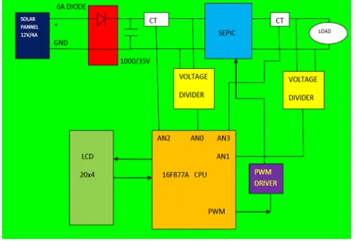
The overall block diagram of hardware is shown in fig. 13. This hardware consists of uses 50 Watts, 21.5V/3.14A solar panel that converts solar energy into Electrical Energy which is applied to the input side of SEPIC (Single Ended Primary Inductor) converter which is dc to dc converter used for step up or step down output voltage than the input voltage as per our requirement. Output voltage of SEPIC converter can be controlled by adjusting duty cycle. Duty cycle is adjusted by adjusting turn ON time of MOSFET which is conducting device of SEPIC converter.
Turn ON time of MOSFET is adjusted by using PWM driver which is controlled by microcontroller 16F877A.
Microcontroller is having 4 inputs to be compared as follows,
AN0 – Input voltage, AN1 – output voltage, AN2 – input current, AN3 – output current.
Microcontroller is programmed in such a way that conducting period of MOSFET should be properly adjusted by PWM driver in order to adjust duty cycle of SEPIC converter such that output voltage (and hence current) is adjusted as per the flowchart of modified Perturb & Observe algorithm. The ultimate goal of doing all this is to avoid drift in MPPT which usually observes in conventional Perturb and Observe algorithm.
[image:7.595.173.424.340.510.2]Overall block diagram and entire hardware structure are shown in fog. 13 & 14 respectively.
[image:7.595.181.418.532.706.2]Fig. 13 overall block diagram of hardware system
Fig. 14 Hardware setup
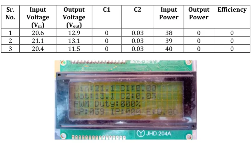
© 2019, IRJET | Impact Factor value: 7.34 | ISO 9001:2008 Certified Journal | Page 660 No load operation corresponds to the condition when SEPIC converter is ON, input power is getting from Solar panel, but output is at no load condition, i.e. does not connected external load across SEPIC converter. Under this condition hardware gave following results summarized in table 2
Table 2 (No load operation)
Sr.
No. Voltage Input (Vin)
Output Voltage (Vout)
C1 C2 Input
Power Output Power Efficiency
1 20.6 12.9 0 0.03 38 0 0
2 21.1 13.1 0 0.03 39 0 0
3 20.4 11.5 0 0.03 40 0 0
Fig. 15 LCD readings of No load operation
On the other hand on load operation corresponds to the condition when input Power is getting from solar panel, SEPIC converter is ON and 200 watts lamp is connected across output of the SEPIC converter. During this condition, hardware gives following result summarized in table 3,
Table 3 (on load operation)
Sr.
No. Voltage Input (Vin)
Output Voltage (Vout)
C1 C2 Input
Power Output Power Efficiency
1 20.1 14.4 0.07 0.29 418 149 86%
2 20.4 14.5 0.11 0.29 418 224 86%
3 20.1 15.1 0.11 0.25 364 224 88%
[image:8.595.87.508.162.404.2] [image:8.595.89.506.509.735.2]© 2019, IRJET | Impact Factor value: 7.34 | ISO 9001:2008 Certified Journal | Page 661 During on load operation output load gets actually connected across input so we get certain efficiency which is not in case of no load operation. Hence during no load operation efficiency is zero. During on load operation both capacitors C1 and C2 shows values greater than those during no load operation. This is due to their charging-discharging during loaded condition.
3. CONCLUSION
This paper proposes a modified perturb and observe MPPT algorithm for drift avoidance in solar PV systems. Drift condition and issues associated with it are deeply explained in this paper. Inclusion of checkpoint for change in current (dI) gives advantage to overcome the problem of drift. SEPIC converter is used to control the output power using direct duty ratio control owing to its numerous advantages. The modified P&O algorithm was validated using MATLAB/Simulink and the results of the simulations prove that the proposed method is drift free. Hardware system is also designed to compare theoretical results with hardware. Hardware results are also much closer to theoretical concepts. It can be concluded that the modified perturb and observe algorithm tracks maximum power point accurately during sudden transients thus improves the efficiency of solar Photovoltaic systems. This method can result in creating greener environment by reducing considerable carbon footprint during entire life span of PV array.
REFERENCES
[1] Muralidhar Killi, Susovon Samanta, “Modified Perturb & Observe MPPT algorithm for drift avoidance in Photovoltaic systems” 2015 IEEE
[2] Mohammed A. Elgendy, Bashar Zahavi, David J. Atkinson, “Assessment of perturb and observe MPPT algorithm implementation techniques for PV pumping applications”, IEEE, January 2012
[3] BOC Group, Operngasse 20b, Vienna, Austria, “An improved perturb & observe MPPT algorithm with variable step”, Scientific Bulletin of the Electrical Engineering faculty, ISSN 2286-2455, [2017]
[4] Dezso Sera, Remus Teodorescu, Jochen Hantschel, Michael Knoll, “optimized maximum power point tracker for fast changing environmental conditions,” IEEE, July 2008
[5] Nicola Femia, Giovanni Petrone, Giovanni Spagnuolo, Massimo Vitelli, “Optimization of Perturb and observe maximum power point tracking method,” IEEE, July 2005
[6] Luigi Piegari, Renato Rizzo, Ivan Spina, Pietro Tricoli “An optimized adaptive perturb and observe maximum power point tracking control for PV generation”, Energies 2015, 8, 3418-3436, ISSN 1996-1073 [2015]
[7] Jehun Hahm, Euntai Kim, Heejin Lee, Changyong Yoon, “A modified Perturb and Observe sliding mode Maximum Power Point Tracking method for PV system under partially shaded condition”, International Journal of Fuzzy Logic & Intelligent Systems, December 2016
[8] Syafaruddin, E. Karatepe, T. Hiyama, “Artificial neural network-polar coordinated fuzzy controller based maximum power point tracking control under partially shaded conditions”, IET Renewable Power Generation, October 2008
[9] E. Mamarelis, G. Petrone, and G. Spagnuolo, “Design of a sliding mode controlled sepic for PV mppt applications,” IEEE Trans. Ind. Electron., vol. 61, no. 7, pp. 3387-3398, Jul. 2014.
AUTHORS PROFILE
Mr. YogeshYashwant Katdare was born in Chiplun on 5th October 1989. He received the B.E.
© 2019, IRJET | Impact Factor value: 7.34 | ISO 9001:2008 Certified Journal | Page 662 Mrs. Pranita Chavan has completed B.Tech from Dr. Babasaheb Ambedkar Technological University in 2001. She also completed M.E. in Electrical Power system from Pune University in 2004. She is working as a Head of the Department in Pillai HOC college of Engineering & Technology, Rasayani.