© 2019, IRJET | Impact Factor value: 7.211 | ISO 9001:2008 Certified Journal
| Page 2335
Load Frequency Control in Two Area Power Systems Integrated with
SMES Combination using Fuzzy-PID and ANFIS Controller
Kavita Choudhary
1, Balvinder Singh
21
Student IEEE member and M. Tech student, EE Dept., Govt. Women Engineering College, Ajmer, India
2Student IEEE member and HOD, EEE Dept., Govt. Women Engineering College, Ajmer, India
---***---Abstract -
:-In this paper, the application of a ANFIS and Fuzzy- PID controllers are proposed for automatic generation control (AGC) and load frequency control (LFC) of two area reheat thermal power plant in interconnected power system. Additionally, a superconducting magnetic Energy Storage (SMES) unit is considering in two areas. The implementation of SMES combination arrests the initial fall in frequency deviation and tie-line power deviation after a sudden load disturbance. The simulation result shows that the system performances are improved significantly with the proposed SMES unit. The sensitivity analysis of the system is performed by varying the parameters and operating load conditions from their nominal values. It is observed that the optimized gains of the proposed PID and fuzzy PID and ANFIS controllers are need not be reset even if the system is subjected to wide variation in loading condition and system parameters. Finally, the effectiveness of the proposed controller design is verified by considering different types of load patterns. The simulated results show that the performance of ANFIS-PID controller is better than the Fuzzy- PID and PID controllers. The simulations have been performed using Matlab software.Key Words
:
Conventional PID controller, fuzzy PID controller, ANFIS controller, load frequency control, membership function, Inter-connected two-area system, Tie-Line power deviation.
1. INTRODUCTION
Load frequency control as one of the most important services in electrical power system design and it has been used for several decades to meet two main objectives, viz., maintain the system frequency deviation and tie-line power interchange deviations within specified values. The fundamental theory of load frequency control has been explained [1-5]. Load frequency control is generally considered as secondary level control and also a dominant operation in the area of automatic generation control (AGC). AGC is a feedback control system adjusting a generator output power to remain defined frequency. LFC system provides generator load control via frequency zero steady – state errors of frequency deviations and optimal transient behaviour are objectives of the LFC in multi-area interconnected power system [6]. Load frequency control (LFC) is being used for several years as part of the automatic
generation control scheme in electric power systems. Among the various types of load frequency controllers, the most widely employed is the conventional proportional integral (PI) controller. The PI, PID and Fuzzy-PID and ANFIS controllers are very simple for implementation and gives better dynamic response, but their performance deteriorate when the complexity in the system increases due to disturbance like load variation . Therefore, there is need of controllers which can overcome these problems. The artificial intelligent controllers like fuzzy and neural control approaches are more suitable in this respect. Literature survey shows that most of earlier work in the area of LFC pertains to interconnected reheat thermal power system. In this paper, the performance evaluation based on ANFIS, Fuzzy-PID and conventional PID for two area thermal interconnected system.
This paper is organized in six sections; the 1st section is the introduction part which is explained above. In section 2nd problem description and controller and objective description of interconnected system is shown. Section 3rd
describes simulation model. 4th
is devoted to the simulation results. Conclusion is derived in section 5th
. 6th
section gives appendix for simulation model.
Area-1 Area-2 Tie- line
Fig.1 Block diagram for two area interconnected power system with tie line
2 Controller Structure and Objective
To control the frequency, PID controller and fuzzy PID controllers are provided in each area. The fuzzy PID controller is show in fig.2.[7] The error inputs to the controllers are the respective area control error (ACE) given by:
e
1(
t
)
ACE
1
B
1
F
1
P
tie (1)tie
P
F
B
ACE
t
© 2019, IRJET | Impact Factor value: 7.211 | ISO 9001:2008 Certified Journal
| Page 2336
2.1Fuzzy-PID Controller
Fuzzy gain scheduling is a procedure normally used for making controllers for power systems dynamic output varies nonlinearly with the operating parameters of the system. It is generally applied when the variation between the system dynamics and operating parameters are given, and for which a linear time- variant model is not enough [14]. Nowadays, gain scheduling is performed according to the step frequency deviation response of the model for various values of the integral gain. A larger value of integral gain reduces the maximum overshoot value of the system frequency but the system oscillation takes place for a longer duration, but higher values of integral gain yield higher maximum frequency but the system oscillation takes place for a longer duration, but higher values of integral gain yield higher maximum frequency deviation in the starting but then delivers effective damping after few cycles, this shows the importance of a variable integral gain, hence large values of integral gain are planned at the beginning and then varied gradually based on the system frequency variations. Here, this methodology to control the performance parameters of the Fuzzy-PID controller according to the change of the new area control error (ACE) and the change in area control error (dACE) [15].
Fuzzy Controller
ACE
dACE
+ + +
Input
I
K
1
s
D
K
dt
d
Output
dt
d
P
K
Fig. 3.. Block diagram for Fuzzy-PID controller
(a)
(b)
[image:2.595.60.280.398.512.2](c)
Fig. 4. Membership function of FGPID controller of a) ACE b) dACE c)
K
p ,K
i andK
dTable 1. Rule base for Fuzzy Logic Controller
ACE/
ACE
NB NS ZZ PS PB NL S S M M BNS S M M B VB
ZZ M M B VB VB
PS M B VB VB VVB
PB B VB VB VVB VVB
For the fuzzy gain scheduled proportion, integral and derivative controller the Manmdani fuzzy inference engine was choose and implemented by triangular membership functions for each of the four semantic variables (
K
p ,K
i andK
d a, ACE ,dACE) with appropriate selection of intervals of the membership functions given.2.2 ANFIS Controller Design
[image:2.595.319.549.524.627.2]© 2019, IRJET | Impact Factor value: 7.211 | ISO 9001:2008 Certified Journal
| Page 2337
ANFIS is consider as an adaptive network and is closely related to ANN. The essential part of neuro-fuzzy modelling comes from a common framework called adaptive network which unifies the neural network and the fuzzy model. An easy rule base model is used for explaining the basic idea of ANFIS architecture. Consider the FIS having Takagi and sugeon’s controller with x and y as two inputs and z as an output. For a first order of sugeno fuzzy model , distinctive rule set are expressed as [18]:
If x is A1 and y is B1 then f1=p1x+q1y+r1
If x is A2 and y is B2 then f2=p2x+q2y+r2
Where p, r and q are linear output parameters. ANFIS architecture including inputs and outputs parameters are show in fig. 5. The formation of the structure involved the use of five layer and two if-then rules.
II II N N 1 A 2 A 1 B 2 B
1 W 2W
1 W 2 W
x
y
f
1,
x
y
f
2,
[image:3.595.311.556.129.210.2]Layer 3 Layer 4 Layer 5 Layer 2 Layer 1 x y x y x y
Fig. 5. Block Diagram of ANFIS Controller
2.3 Analysis of SMES and Its Control Strategy
Super conducting Magnetic Energy Storage (SMES) is a device which can store the electrical power from the grid in the magnetic field of a coil. The magnetic field of coil is made of superconducting wire with near-zero loss of energy. SMESs can store and refurbish huge values of energy almost instantaneously. Therefore the power system can discharge high levels of power within a fraction of a cycle to avoid a rapid loss in the line power. The SMES device is consisting of inductor-converter unit, dc super-conducting inductor, AC/DC converter and step down transformer. The stability of the SMES device is superior to other power storage device; because all parts of an SMES units are static. Superconducting coil will be charged to a normally less than the maximum charge from the utility grid. The DC magnetic coil is connected to the AC grid through a power conversion system which includes an inverter and rectifier. After being charged the superconducting coil conducts current, which supports an electromagnetic field. With virtually no losses. The coil is kept at extremely low temperature. When there is a sudden increase in load demand, the stored energy in the super conducting coil is released in the form of AC through
the power conversion system (PCS) to the electrical network. [11-13] -+ + + SMES K DC sT 1 1 id
K
sL 1Error Ed
d
E
Il0Il
0
l
I
Fig.6. Block diagram of SMES unit with negative feedback signal
When after applying the negative feedback signal then inductor current deviation
E
d becomes
SMES i i tieji id l
DC
d
K
B
W
P
K
I
sT
E
1
1
(3)3. Simulation Model
Analysis of the different types of controllers has been implemented on different interconnected power system models. Once the tuning of the controller is done than we have to give a unit step function to over simulink model of the power system to check the simulation result for ANFIS and Fuzzy-PID controller with matlab/simulink.
+ + PID/ Fuzzy-PID Controller -+ -+ B 1 + -+ + PID/ Fuzzy-PID Controller + -+ + B 2 1 1 R 1 1 1 H sT
1 1
1 T sT 1 1 1 1 1 R R R sT T sK SLP 1 1 1 PS PS sT K s T12 2 1 R 2 1 1 H sT
1 2
1 T sT 2 2 2 1 1 R R R sT T sK 2 2 1 PS PS sT K AREA1 AREA2
Reheat steam turbine Reheat steam turbine
Hydraulic amplifier Hydraulic amplifier
Fig. 7. Simulation model diagram for two area Reheat power system
4.
Result discussion
4.1) Frequency and Tie-Line Power Response
[image:3.595.71.279.328.468.2] [image:3.595.309.588.445.616.2]© 2019, IRJET | Impact Factor value: 7.211 | ISO 9001:2008 Certified Journal
| Page 2338
interconnected power system respectively ANFIS-PID, Fuzzy-PID and PID controllers.
[image:4.595.325.543.135.276.2][image:4.595.55.266.138.276.2]
Fig. 8. Frequency Deviation in area 1 (Pu Hz)
Fig. 9. Frequency Deviation in area 2 (Pu Hz)
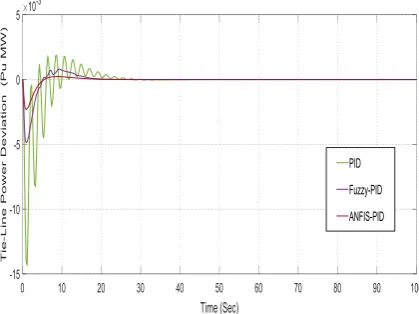
Fig. 10. Tie-Line Power Deviation in areas (Pu MW)
[image:4.595.332.560.287.471.2]4.1) Frequency and Tie-Line Power Response with SMES Unit
Fig. 11. Frequency Deviation in area 1 with SMES unit
Fig. 12. Frequency Deviation in area 2 with SMES unit
[image:4.595.55.270.311.452.2] [image:4.595.58.268.492.649.2] [image:4.595.332.553.508.671.2]© 2019, IRJET | Impact Factor value: 7.211 | ISO 9001:2008 Certified Journal
| Page 2339
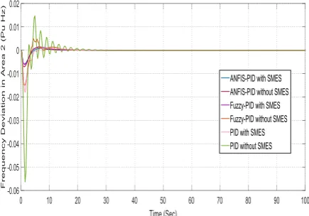
[image:5.595.54.275.131.295.2]4.1) Comparison of Frequency and Tie-Line Power Response with and without SMES
[image:5.595.55.273.338.490.2]Fig. 14. Comparison of Frequency Deviation in area 1
Fig. 15. Comparison of Frequency Deviation in area 2
Fig. 16. Comparison of Tie-Line Power Deviation in areas
4.1) Controllers and Parameters Table for Results Discussion
In table 2,3 analysis of frequency deviation is show with respect to settling time and minimum undershoot and overshoot value using PID and Fuzzy-PID and ANFIS-PID Controllers for each subarea of the two area system.
Table 2. Performance Analysis of Frequency Response for Area 1
S.NO.
Parameters PID Controller
Fuzzy-PID Controller
ANFIS-PID Controller
1. Peak
Undershoot (Hz)
-0.05 -0.02 -0.01
2. Peak
Overshoot (Hz)
0.15 0.05 _
3. Settling Time
(Sec)
30
20
10
Table 3. Performance Analysis of Frequency Response for Area 2
S.NO.
Parameters PID Controller
Fuzzy-PID Controller
ANFIS-PID Controller
1. Peak
Undershoot (Hz)
-0.052 -0.015 -0.005
2. Peak
Overshoot (Hz)
0.15 0.05 _
3. Settling Time
(Sec)
30
20
[image:5.595.58.274.530.714.2]10
Table 4.Performance Analysis of Tie Line Power in areas
S.NO.
Parameters PID Controller
Fuzzy-PID Controller
ANFIS-PID Controller
1. Peak
Undershoot (Hz)
-0.014 -0.005 -0.002
2. Peak
Overshoot (Hz)
0.002 0.001 _
3. Settling Time
(Sec)
30
20
[image:5.595.297.569.589.730.2]© 2019, IRJET | Impact Factor value: 7.211 | ISO 9001:2008 Certified Journal
| Page 2340
Table 5. Performance Analysis of frequency Deviation in area 1 with SMES
S.NO. Parameters PID with SMES Fuzzy-PID with SMES
ANFIS-PID with SMES
1. Peak
Undershoot (Hz)
0.021 -0.009
-0.008
2. Peak
Overshoot (Hz)
0.002 0.002 0.0001
3. Settling Time
[image:6.595.309.556.334.578.2](Sec) 25 15 10
Table 6. Performance Analysis of frequency Deviation in area 2 with SMES
S.NO. Parameters PID with SMES Fuzzy-PID with SMES ANFIS-PID with SMES
1. Peak
Undershoot (Hz) -0.016 -0.006 -0.005
2. Peak
Overshoot (Hz) 0.002 0.002 0.0001
3. Settling Time
(Sec) 25 15 10
Table 7. Performance Analysis of Tie-Line Power Deviation in areas with SMES
S.NO. Parameters PID with SMES Fuzzy-PID with SMES ANFIS-PID with SMES
1. Peak
Undershoot (Hz) -0.006 -0.0025 -0.0021
2. Peak
Overshoot (Hz) 0.002 0.002 0.0001
3. Settling Time
(Sec) 25 15 10
5.
Conclusion
Investigation of two area system has been done with ANFIS-PID and Fuzzy-ANFIS-PID logic and ANFIS-PID controllers. This paper presents to contribute towards building an intelligent, fast and better controller for load frequency control (LFC) of consider nonlinear interconnected power system. In overview, it is observed with significant improvements of dynamic responses are obtained with coordinated
application of ANFIS-PID and Fuzzy-PID based controllers. Further, SMES unit is added in the system model in order to improve the system performance. It is observed that when the SMES unit is placed with the load line, dynamic performance of system is improved. Then the impact of SMES in the AGC along with UPFC is also studied. From the simulation results, it is observed that significant improvements of dynamic responses are obtained with coordinated application of SMES. Finally, sensitivity analysis is carried out to show the robustness of the controller by varying the loading conditions and system parameters in range of 1% to 2% from their nominal values. It is observed from simulation results that proposed controller performed well against random load patterns when system is incorporated with SMES compared to other.
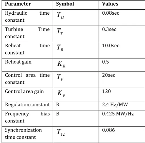
6. APPENDIX
Table 8. Parameter of the system and their nominal values [5]
Parameter Symbol Values
Hydraulic time
constant
T
H0.08sec
Turbine Time
constant
T
T0.3sec
Reheat time
constant
T
R 10.0secReheat gain
R
K
0.5Control area time
constant
T
P20sec
Control area gain
P
K
120Regulation constant R 2.4 Hz/MW
Frequency bias
constant
B 0.425 MW/Hz
Synchronization
time constant
T
12 0.086References
1. Satish Kumar Meena, Saurabh Chanana, Comparative
Study Of Load Frequency Control Using PID and FGPI
Controller, IEEE power India International Conference, pp.1-6 (2014).
2. K. Sabahi M.A. Nekoui M. Teshnehlab M. Aliyari M. Mansouri Load frequency control in interconnected power system using modified dynamic neural networks” proceeding of the 15th Mediterranean
conference on control and amp; Automation pp. T26-011 (2007).
© 2019, IRJET | Impact Factor value: 7.211 | ISO 9001:2008 Certified Journal
| Page 2341
4. Manoj Kumar Debnath, Ranjan Kumar Mallick, Sadhana Das, Aditya Aman “Gravitational Search Algorithm (GSA) Optimized Fuzzy-PID Controller Design for Load Frequency Control of an Interconnected Multi-Area Power System” International Conference on Circuit, Power and Computing Technologies, pp.1-6 (2016).
5. Hauk Gozde M.Cengiz Taplamacioglu IIhan Kocaarslan, Comparative performance analysis of Artificial Bee Colony algorithm in automatic generation control for interconnected reheat thermal power system, International Journal of Electrical Power and amp; Engergy Systems vol.42 no.1 pp.167- 178 (2012).
6. K. A. Ellithy ,K. A. El-M etwally, Design of Decentralized Fuzzy Logic Load Frequency Controller, I.J. Intelligent Systems and Applications vol. 2 pp.66-75 (2012).
7. W .C. Chan, Y. Y. Hsu, Automatic Generation Control of Interconnected Power Systems Using Variable Structure Controller, IEE Proc. On Generation Transmission and Distribution Pt. pp. 269-279 (1981).
8. Afshan Ilyas, Shagufta Jahan, MohammadAyyub, Tuning Of conventional Pid and Fuzzy Logic Controller Using Different Defuzzification Techniques, International journal of scientific and technology research, vol.2 issue1, pp.138-142 (2013).
9. Nilay. N. Shah, Aditya. D . Chafekar, DWIJ. N. Mehta and Anant. R. Suthar, Automatic Load Frequency Control of Two area Power System with Conventional and Fuzzy Logic Control, International Journal of Engineering Research and Technology, vol. 1,issue 3, pp. 343-347 (2014).
10. M. Nagendra, M. S. Krishnarayalu, PID Controller Tuning Using Simulink for Multi Area Power Systems, International Journal of Engineering Research and Technology vol. 1 issue7 (2012). 11. V.Shanmugasundaram, T.Jayabarathi, A Fuzzy
approach of autonomous power generating systems, Procedia engineering vol.38, pp.753-762 (2012). 12. T.C. Yang Z.T. Ding H. Yu "Decentralized power
system load frequency control beyond the limit of diagonal dominance" Electrical Power and Energy Systems vol. 24 no. 3 pp. 173-184 (2002).
13. Banerjee, Chatterjee JK, Tripathy SC. Appliction of magnetic energy storage unit as load- frequency stabilizer. IEEE Trans Energy Converse5 (1) pp.46-51 (1990).
14. Tripathy SC, Juengst KP. Sampled data automatic generation control with superconducting magnetic energy storage in power system. IEEE Trans Energy Converse 12(2): pp.187-92 (1997).
15. Abrasham RJ, Das D, Patra . Automatic generation control of an interconnected hydrothermal power system considering superconducting magnetic
energy storage. Int J Electr Power Energy Syst 29(8): pp. 571-9 (2007).