© 2016, IRJET | Impact Factor value: 4.45 | ISO 9001:2008 Certified Journal | Page 356
HIGH PERFORMANCE BAUGH WOOLEY MULTIPLIER USING
CARRY SKIP ADDER STRUCTURE
R.ARUN SEKAR
1B.GOPINATH
21Department Of Electronics And Communication Engineering , Assistant Professor, SNS College Of Technology,
Coimbatore, India.
2Department of Electronics and communication Engineering , Associate Professor, Info Institute of Engineering,
Coimbatore, India.
---Abstract: The Baugh-Wooley algorithm is a fine
recursive algorithm for performing multiplication in number of digital signal processing applications. The crictical path delay is reduced by using this algorithm and the speed is enhanced. In this research paper a high speed multiplier is designed and implemented using decomposition logic and Baugh-Wooley algorithm. The outcome is compare with vedic and modified booth multiplier. FPGA based architecture is presented and design has been implemented using Xilinx 12.3.Here the number of partial products has been reduced and its performance has been increased. We apply the Baugh-Wooley algorithm in different Multipliers and the Baugh-Wooley multipliers exhibit less delay, less power dissipation and smaller area than vedic and modified-Booth multipliers.
Keywords:Carry skip adder (CSA), Baugh wooley
multiplier, high performance, Modified booth multiplier, vedic Multiplier.
I. INTRODUCTION
Multipliers play a vital role in various high performance systems such as Microprocessor, FIR filters, Digital Processors, etc. Multipliers are a crucial part of the modern electronic era. Multipliers can found electronics systems that run compound calculations especially in DSP processor,
Microcontroller and Microprocessor. Many transform algorithms like Fast Fourier transforms (FFTs), DFT etc make use of various multipliers Multiplication is an important arithmetic operation and multiplier implementations date a number of decades back in time. Multiplications were originally performed by iteratively utilizing the ALU’s adder. As time constraints became stricter with increasing clock rates, keen multiplier hardware implementations such as the array multiplier were introduced. Low power adder circuits have become very important in VLSI industry.
1.1 Adder Circuits
© 2016, IRJET | Impact Factor value: 4.45 | ISO 9001:2008 Certified Journal | Page 357 these units, which has been reported in [2]–[9].
Obviously, it is extremely possible to achieve top speeds at low-power and energy consumptions, which is one of the challenges for the designers of general purpose processors
II.BAUGH-WOOLEY MULTIPLIER
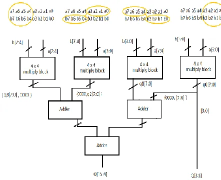
[image:2.612.66.226.430.636.2]In signed multiplication the duration of the partial products and the number of partial products will be very high. So an algorithm was introduced for sign multiplication called as Baugh Wooley algorithm. The Baugh-Wooley multiplication is one amongst the cost-effective ways to hold the sign bits. This method has been developed so as to style regular multipliers, suited to 2's compliment numbers. Baugh-Wooley multiplier hardware architecture is shown in figure 2.1. It follow left shift algorithm.
Figure 2.1 Hardware implementation of Baugh-Wooley Multiplier
Mux can choose which bit will multiply. Suppose we multiply +4 and -4 in decimal we get ‘0’. Now, after representing these numbers in two’s compliment form we get +4 as 0100 and -4 as 1100. On adding these two binary numbers we get 10000. Discard carries, then number is represented as ‘0’.As shown in Figure 2.1 Baugh-Wooley Multiplier provides a high speed, signed multiplication algorithm [5]. It uses similar products to complement multiplication and adjusts the partial products to maximize the regularity of multiplication array [6]. When digit is represented in two’s complement form, sign of the number is embedded in Baugh-Wooley multiplier.
III. BAUGH-WOOLEY MULTIPLICATION
© 2016, IRJET | Impact Factor value: 4.45 | ISO 9001:2008 Certified Journal | Page 358
Figure 3.1 Structure of BAUGH WOOLEY multiplication
IV.MODIFIED BOOTH MULTIPLIER
Booth introduced an capable multiplication algorithm [8] , which has a reduced delay in order of O( log n ) . The logarithmic raise in delay with respect to operand size provides speed gain over array multiplier which has a linear raise in delay . In this multiplier architecture all the bits of all the partial products in a column are added together in similar without the propagation of any carries.
Figure 4.1 Structure of MODIFIED BOOTH MULTIPLIER
The process is repeated till there is only two rows of the matrix is left, the two rows are then added with a fast adder. Here a 3:2 compressor is used which is based on carry save adder. The modified Booth multiplier is shown Figure 4.1.
V .VEDIC MULTIPLIER
[image:3.612.329.550.363.543.2]Oldest method of multiplication.Here adders are used for multiplications.Different types of adders can be used for multiplication.The efficient adder used is carry skip adder(CSA).The architecture of vedic multiplier is shown in figure 5.1. In this multiplier architecture all the bits of all the partial products in a column are added together in similar without the propagation of any carries.
Figure 5.1 Structure of MODIFIED BOOTH MULTIPLIER
VI. RESULT AND DISCUSSION
[image:3.612.43.260.481.656.2]© 2016, IRJET | Impact Factor value: 4.45 | ISO 9001:2008 Certified Journal | Page 359 operates on maximum frequency of 95.9MHz. The
considerable raise in speed make the design suitable for many high performance system such as Digital Signal Processors, FIR filters, Microprocessors etc. When multiplying twos compliment numbers directly, each of the part products to be added is a signed numbers. Thus all partial product has to be sign extended to the width of the final product in order to form a correct sum by the Carry Skip Adder (CSA) tree.
VII. CONCLUSION
The logic depth through the reduction tree differs by only one or two full adders for a modified-Booth,vedic and Baugh-Wooley implementation of the same operand bit-width. Considering that the critical path of a modified-Booth multiplier is located in its encoder and decoder, it is difficult to envision a modified-Booth implementation that can be much faster than a Baugh-Wooley implementation, regardless of the recoding scheme used. Taking power, energy per operation, and area into consideration, it is clear that the gain by reducing the reduction circuitry is lost in the recoding circuitry, making a modified-Booth implementation perform worse than a Baugh-Wooley implementation
REFERENCES
1. T. K. Callaway and J. Earl E. Swartzlander, “Power-Delay Characteristics of CMOS Multipliers,” in Proceedings of the 13th IEEE Symposium on Computer Arithmetic, June 1997, pp. 26–32.
2. O.L.MacSorley, “High Speed Arithmetic in Binary Computers,” in Proceedings of the IRE, vol. 49, no. 1, January 1961, pp. 67–97.
3. J. Fadavi-Ardekani, “MxN Booth Encoded Multiplier Generator Using Optimized Wallace trees,” IEEE Transactions on Very Large Scale Integration (VLSI) Systems, vol. 1, no. 2, pp. 120–125, 1993.
4. W.-C. Yeh and C.-W. Jen, “High-Speed Booth Encoded Parallel Multiplier Design,” IEEE Transactions on Computers, vol. 49, no. 7, pp. 692–701, July 2000.
© 2016, IRJET | Impact Factor value: 4.45 | ISO 9001:2008 Certified Journal | Page 360 6. H. Eriksson, P. Larsson-Edefors, M. Sheeran,
M. Själander, D. Johansson, and M. Schölin, “Multiplier Reduction Tree with Logarithmic Logic Depth and Regular Connectivity,” in IEEE International Symposium on Circuits and Systems, May 2006.
7. C. R. Baugh and B. A. Wooley, “A Two’s Complement Parallel Array Multiplication Algorithm,” IEEE Transactions on Computers, vol. 22, pp. 1045–1047, December 1973.
8. M. Hatamian, “A 70-MHz 8-bit x 8-bit Parallel Pipelined Multiplier in 2.5-µm CMOS,” IEEE Journal on Solid-State Circuits, vol. 21, no. 4, pp. 505–513, August 1986.
9. M.Själander, “HMS Multiplier Generator,” http://www.sjalander.com/