© 2015, IRJET ISO 9001:2008 Certified Journal Page 2225
SIMULATION AND MODELING OF SINGLE PHASE DC-AC CONVERTER OF
SOLAR INVERTER
Maulik Dave
1, Prof. Sanjay R. Vyas
21
M.E. scholar, Electrical engineering department, LDRP-ITR, Gandhinagar, Gujarat, India
2
Professor at Electrical engineering department, LDRP-ITR, Gandhinagar, Gujarat, India
---***---Abstract -
This paper is depicts information about dc-acinverter used in solar inverter. We will get DC power from solar panels and this converter inverts DC to AC. This design and modulation is based on MATLAB software. In circuit, for switching purpose IGBT is used. There are many other devices also but IGBT has more advantages than others which are shown by comparison with others. The main thing is that this conversion and switching of IGBT is done using different types of PWM methods. Here we are using SPWM method for conversion of AC power. This method is very efficient than other methods and also it reduces harmonics to very much extent in output. Project objective are, to design an inverter model by using MATLAB and making analysis on the output voltage and to study the function of PWM in single phase inverter. Project scope are,
1. Modeling and simulation using MATLAB.
2. Using PWM method for the switching operation. Project application: This Project is based on solar inverter, this inverter will be used in our college for lab applications.
Key Words:
Single phase DC-AC converter, IGBT,
MATLAB, SPWM method, harmonic reduction, etc.
1. INTRODUCTION
Presently world is facing too much challenges one of them is to generating the enough electrical power that will fulfil
the requirements of mankind. Today generation of electrical power based on the conventional coal, gas and nuclear based. World population is increasing day by day so the requirement of them also increased and hence generation of electrical power is also increased. Basically there are two types of power generation sources: 1. Conventional 2. Nonconventional. Today most of generation of electrical power based on Conventional sources such as coal, gas and nuclear etc. Conventional sources are no more after some of the years and which are not sufficient to fulfill the requirement of the mankind. Nuclear energy is not much preferable because its radiation effect. Therefore some part of energy should be generated based on non-conventional sources. There are also problems of increasing pollution and energy demands and hence the exploitation of solar has received more and more attentions. This project is also focus on modeling and simulation of single phase solar inverter by Pulse Width Modulation. Pulse Width Modulation is a technique that use as a way to decrease total harmonic distortion in inverter circuit. The model is implemented using MATLAB software with the SIMPOWER SYSTEM block set based on computer simulation. Computer simulation plays an important role in the design, analysis, and evaluation of power electronic converter and their controller. MATLAB is an effective tool to analyze a PWM inverter. Advantages of using MATLAB are the following: 1. faster response 2. Availability of various simulation tools 3. Various functional blocks, etc.
© 2015, IRJET ISO 9001:2008 Certified Journal Page 2226 FIGURE 1: GENERAL DIAGRAM OF SOLAR INVERTER
SYSTEM
In general diagram it is shows that from energy of sun, solar panel is being heated. Due to heating of solar panel, DC power will be generate. This power will be given to MPPT (maximum power point tracking) which will transfer maximum efficient power to the DC-DC boost converter. Now DC-DC boost converter will boost it to specified DC voltage which will be appropriate to inverter. Inverter will convert this DC voltage into required AC voltage. But this AC voltage will be pulsating and contains some harmonics, to reduce it filter is being placed. After passing from filter, it will be pure AC power and ready for load consumption. Here, generation of electricity is based on photovoltaic effect. Photovoltaic systems are comprised of photovoltaic cells, devices that convert light energy directly into electricity. Photovoltaic offers consumers the ability to generate electricity in clean, quiet and reliable way. Because the source of light is usually the sun, they are often called solar cells. The word photovoltaic comes forms “photo” meaning light and “voltaic” which refers to producing electricity. Therefore, the photovoltaic process is “producing electricity directly from sunlight”. Photovoltaic are often refereed as PV. In section III dc-ac bridge inverter, different types of inverters, in section IV filters, in section V PWM techniques and in section VI simulation result are explained.
2. DC-AC BRIDGE INVERTER
There are two types of inverters. 1. VSI (voltage source inverter) 2. CSI (current source inverter). Here we are using VSI. A voltage source inverter (VSI) is one that takes in a fixed voltage from a device, such as a dc power supply, and converts it to a variable-frequency AC supply. Also it easier to convert AC voltage from DC voltage. A solar inverter is a power-electronic circuit that converts dc voltage from a solar array panel to ac voltage that can be used to power ac loads such as home appliances, lighting and power tools. However, getting the most out of such a topology requires careful analysis and the right choice of the high-side and low-side combination of an IGBT. According to our requirement, here we consider single phase 2 Arm Bridge – 4 pulse converter for solar inverter.
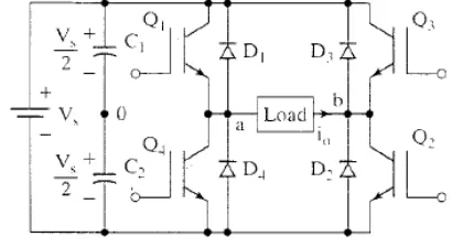
Figure 2: BRIDGE INVERTER
In above figure it is shown that, there are total four converter (IGBT) namely Q1, Q2, Q3, Q4. Q1-Q2 and Q3-Q4 switched on and off alternately. Each pair provide opposite polarity of Vs across the load. Diodes are placed for freewheeling during inductive load.
[image:2.595.332.537.391.503.2]© 2015, IRJET ISO 9001:2008 Certified Journal Page 2227 Figure 3: Q1-Q2 on, Q3-Q4 off
At first Q1-Q2 is on and Q3-Q4 is off. During this cycle current passes from load as shown in figure. So that output is Vab = Vs.
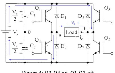
For Vab = -Vs
Figure 4: Q3-Q4 on, Q1-Q2 off
After that Q3-Q4 is on and Q1-Q2 is off. During this cycle direction of current is changed so that negative voltage is produced across load. So that Vab = -Vs.
WHY IGBT IS USED?
IGBT is used due to its easy control and low switching losses. Also it is available in wide range of ratings. Comparison with that different devices is shown below.
Sr . N o.
Parameter SCR Power BJT
Power MOSFE T
IGBT
1 Operating frequency
400 to 500 Hz
10kHz 100kH z
10kHz
2 On state voltage drop
< 2 V < 2 V 4 – 5 V 3 V
3 Maximum VI ratings
10 kV / 5kA
2 kV / 1kA
600 V / 200A
1.5kV / 400A
4 Type of device Minorit y carrier Minorit y carrier Majorit y carrier Minorit y carrier
5 Voltage/cur rent controlled
Current Curren t
Voltage Voltage
6 Commutatio n circuit Necess ary Not necess ary Not necess ary Not necess ary
3. FILTERS
[image:3.595.60.262.361.490.2]© 2015, IRJET ISO 9001:2008 Certified Journal Page 2228 Figure 5: L-C filter
LC filter can be used for minimization of harmonics at output side of the inverter.
Calculation of L and C:
The inductive part of the low pass filter is designed based on the allowable current ripple at switching frequency on the grid side.
L = VDC / 4*fs*Δi
Where VDC is the DC voltage, Δi value of the current ripple. fs is switching frequency
For, calculation of capacitor,
C = Δi / 8*fs*Δv0,
Where, Δv0 = voltage ripple
4.
DIFFERENT TYPES OF PWM TECHNIQUESThe most efficient method of controlling output voltage is to incorporate PWM control within inverters. In this method, a fixed d.c. voltage is supplied to inverter and a controlled a.c. output voltage is obtained by adjusting on-off period of inverter devices. Pulse Width Modulation variable speed drives are increasingly applied in many new industrial applications that require superior performance. Recently, developments in power electronics and semiconductor technology have lead improvements in power electronic systems.
There are many different types of PWM techniques, which is shown in below diagram. In this chapter we will see the different types of PWM techniques are available for controlling the output ac voltage for the inverter. In many industrial applications, to control of the output voltage of inverters is often necessary with varying the DC input voltage. With the help of the PWM techniques we can control the output voltage of the inverter and vary the gain of inverter.
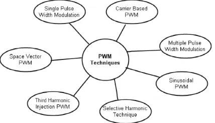
There are number of PWM techniques are available to control the inverter output voltage which are as follows:
Figure 6: different types of PWM techniques
PWM techniques are characterized by constant amplitude pulses. The width of these pulses is however modulated to obtain output voltage control and to reduce its harmonic content. Here three different PWM techniques which are generally used are explained below. Those are Single-pulse modulation, multiple Single-pulse modulation and Sinusoidal pulse width modulation (Carrier based Pulse Width Modulation Technique). Here only carrier based PWM technique is explained which is used in this project.
1. Carrier based PWM inverter
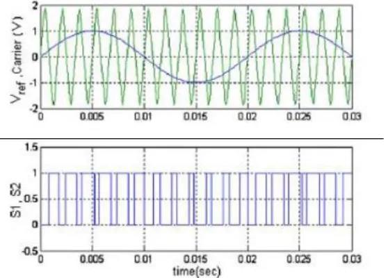
[image:4.595.331.545.334.457.2]© 2015, IRJET ISO 9001:2008 Certified Journal Page 2229 versa. In other words, the switching signal starts if the
[image:5.595.44.266.224.397.2]reference signal is greater than the carrier signal, and the switching signal ends if the carrier signal is greater than the reference signal. Note that the effective value of the switching signals looks sinusoidal, and each pulse width is related to the reference wave amplitude as seen in figure.
Figure 7: switching of IGBT using PWM technique
Figure 8: Generating PWM waveform
The reference wave amplitude is changed to adjust the output voltage of the inverter. The output voltage harmonic component is in the following form
MPxc ± Nxs
where xc is the carrier wave frequency, xs is the reference (modulation) frequency, M and N are integers, M + N is an odd number and P is a constant that is proportional with the carrier/reference frequency.
mf = fs / fl
And an amplitude modulation index: ma = vcontrol / vdiscrete
5. SIMULATION RESULT
[image:5.595.41.320.468.668.2]Figure 9: Simulation circuit
Figure 10: Current and voltage waveform
6. CONCLUSION
© 2015, IRJET ISO 9001:2008 Certified Journal Page 2230 our college lab load for example tube lights, fans, etc. by
this we can save energy to some extent.
REFERENCES
[1]. F. Z. Peng, “Z-Source inverter,” IEEE Trans. Ind. Appl., vol. 39, no. 2,pp. 504–510, Mar.03
[2]. F. Gao, P. C. Loh, R. Teodorescu, and F. Blaabjerg, “Diode-assisted buck–boost voltage source inverters,”
IEEE Trans. Power Electron., vol. 24,no. 9, pp. 2057–2064,
Sep. 2009.
[3]. Improved PWM strategies for diode assisted buck-boost voltage source inverter by Yan Zhang, Student
Member, IEEE, Jinjun Liu, Senior Member, IEEE, and Chaoyi
Zhang.
[4]. Chiasson JN et al. A complete solution to the harmonic elimination problem. IEEE Trans Power Electron 2004; 19(2):491–9.
[5]. Soeren Baekhoej Kjaer, John K. Pedersen, and Frede Blaabjerg, “A Review of Single-Phase Grid-Connected Inverters for Photovoltaic Modules” IEEE Transactions on Industry Applications, vol 41,No.5,September/October 2005.
[6]. ZHENYU YU AREFEEN MOHAMMED ISSA PANAHI. “A Review of Three PWM Techniques”American Control Conference, 1997. Proceedings of the 1997, vol6, 6 June 1997.
[7]. Vlatko Vlatkovi C, DuSan Borojevi C, and Fred C. Lee, “Input Filter Design for Power Factor Correction Circuits”, IEEE transactions on power electronics, vol. 11, no. 1, January 1996.
[8]. A Novel Single-Stage Full-Bridge Buck-Boost Inverter Chien-Ming Wang Department of Electronic Engineering
Lunghwa University of Science and Technology 300, Wan-Shou Road, Sec. 1, Kueishan, Taoyuan, Taiwan (333), ROC. The National Science Council sponsored the work, Project no. NSC90-2622-E-011-001.
[9]. N. R. Zargari, P. D. Ziogas, and G. Joos, “A Two-Switch High-Performance Current Requlated DC/AC Converter Module,” in IEEE Trans. Industry Application. vol. 31, no. 3, pp.583-589, 1995.