© 2016, IRJET | Impact Factor value: 4.45 | ISO 9001:2008 Certified Journal
| Page 1488
Performance Study On Deflection Control For Tall Buildings In
Seismic Zone III for Different Structural Framing System
Sangeetha k
1,
Vinod Shavare
2,
G H Basavaraj
31
Post Graduate Student, Department of Civil Engineering, EWIT, Karnataka, India
2Assistant Professor, Department of Civil Engineering, EWIT, Karnataka, India
3
G H Basavaraj, Managing director, Chetana Engineering services Pvt. Ltd, Bangalore, Karnataka, India
---***---Abstract -
: Nowadays tall building development is rapidlyincreasing. In the present study an attempt is made to evaluate deflection control of 30 story commercial building using E-tabs software. Different structural framing systems are applied to know the building performances in Zone III. Response spectrum method is used due to its innate simplicity of computation. Models are prepared with bare frame having central core, braced frame, shear wall frame system in order to get effective lateral load resisting system. Though the structural cost of tall building is around 20 to 25% of total cost, optimizing the design by repetitive design process, considerable savings could be achieved. Results includes time period, maximum story deflection, maximum story drift, base shear absorption, Stability against overturning moment, for different framing system in zone III and are presented in tabular form.
Key Words
:
ETABS 9.7.4, response spectrum method,
stiffness, IS1893 -2002, IS456-2000, shear wall, bracings.
1.INTRODUCTION
Earthquake is one of the frightening and destructive phenomena of nature. Due to that it’s very difficult to save engineering structures and human life. To overcome this the buildings are constructed with shear walls frequently to resist horizontal loads due to earthquake and wind. They are generally provided between columns, stair wells and lift pit. It provides horizontal load resisting by transferring the earthquake or wind load to the foundation. RC framed buildings are adequate for resisting both vertical and lateral load. But for tall buildings column and beam sizes are bigger. Due to this there is lot of congestion at joint and it is hard to place concrete and vibrate it and displacement is quite heavy which induces heavy forces in members. They are generally used in high rise buildings to avoid damage of buildings.
Shear walls acts like flexural members. They are generally used in high rise buildings to avoid damage of buildings. Shear wall may become helpful from the point of economy and control horizontal deflection. When shear wall are situated in advantageous position in the building they can form an efficient lateral force resisting system
Classification of shear wall according to shape: 1. Box section ( rectangular shaped section ) 2. L-shaped section
3. U-shaped section 4. W- shaped section 5. H -shaped section 6. T- Shaped section.
Fig-1:Classification of shear wall according to shape
© 2016, IRJET | Impact Factor value: 4.45 | ISO 9001:2008 Certified Journal
| Page 1489
This structural system is used to minimize excessive driftcaused by lateral forces and increases the building stiffness.. Types of bracings:
V-Bracing X-Bracing
Inverted V-Bracing Diagonal bracing K-bracing
Fig-2 Types of bracings
[1] Ashwinkumar Balaso Karnale1 , Dr. D. N. Shinde2 presented the “Comparative Seismic Analysis of High Rise and Low Rise RCC Building with Shear Wall”.
It is so necessary to assess the seismic performance of shear walls appropriately. Along with that it is important to check out the effective positioning of shear wall in the building. This study gives the values for various configurations of shear walls for 6 and 14 storey structures. Analysis in done in this dissertation lateral force. Provision of shear walls is more effective in high rise structure than in low rise structure.. Shear wall placed at corner of the structure gives deflection in allowable limits along with that minimum base shear value. Hence it is less susceptible to lateral force. Compared to bare frame, time period is less for frame with shear wall hence attracts greater base shear. Various structural parameters are affected by location of shear wall. If the shear walls are needed to be provided at corners then L-shaped walls are effective. But in low rise buildings,
provision of shear wall at different position does not affect much for structural parameters as compared to high rise structure.
[2]1. N. Janardhana Reddy, D. Gose Peera and T. Anil Kumar Reddy worked on “Seismic Analysis of Multi-Storied Building with Shear Walls Using ETABS-2013”. In this research multi storey structure having 14 storeys is modeled and it is analyzed for its stability, displacement and strength with the help of ETAB-2013 software. To analyses the structure for lateral earthquake force for zone-II and zone-V and soil type taken as soil I and soil III type. Analysis is carried out by equivalent static and dynamic method. By introducing and aligning of shear wall influence the center of rigidity and center of mass. Here it is clearly justified that no torsion effect can be noticed if the building is symmetric hence shear walls should be located in a symmetric manner. Along with that building performance is better when it is provided with shear wall compared to building without shear wall because of center of rigidity and center of mass becomes nearer. As the provision of shear wall increases the stiffness of structure, displacement is reduced and it can resist lateral forces. By the application of response spectrum method better performance with respect to displacement can be obtained. As the shear walls introduced in building, shear force resisted by column frame reduced, since shear wall has taken that role. Hence moment resisting frame along with shear wall can efficiently resist lateral loads like earthquake and wind forces. Shear wall imparts lateral load distribution by carrying lateral load to foundation, along with that it also take part in carrying gravity loads. Shear walls are little costly but worth having for safe structure hence providing them from foundation to top level of the structure can give excellent performance against lateral forces.
© 2016, IRJET | Impact Factor value: 4.45 | ISO 9001:2008 Certified Journal
| Page 1490
of shear wall location in buildings subjected to seismicloads”.
In order to resist lateral loads and to provide strength and stability, shear system is the most popularly used framing system in high rise structure. In this paper comparison for storey drift deflection, storey shear, percentage of column reinforcement etc for a structure subjected to lateral force depending on strategic location of shear wall id done. Sixteen storey building is considered. Having ground storey and typical storey height as 3m. Soil is of medium type.
In medium elevated structures introducing shear walls is observed to be effective in upgrading the overall seismic limiting characteristics of the structure. From the examination of story drift values it can be seen that greatest diminished in drift values is acquired when shear walls are given at corners of the structure. Lateral displacement results acquired from static method for analysis demonstrates that shear wall implementation in longitudinal and transverse direction are successful in decreasing the displacement values in the same direction. results obtained from response spectrum analysis gives a more sensible behavior of structure reaction and henceforth it can be noted that the displacement values in both X and Y direction are minimum in model with shear wall in center and corners when tallied with different models. The reinforcement necessity in column is influenced by the orientation and position of adjacent shear walls and columns, ie arrangement along stronger or weaker axis for the building under process. In spite of the fact that the demand is changing, it could be observed that the column arranged close to core region shows diminished in steel necessity up to 44.6% when shear wall is given at the center and 34.7% when shear wall is situated at centr and corner of the structure.
[4]
Er. Raman Kumar proposed “The structural behaviorof the buildings with different locations of shear walls”
Building is investigated and compared in terms of storey drift, average displacement and member forces induced in the various members of the buildings. Regular buildings with two RC framed with different shear wall locations situated in zone V were analyzed in this study. Ten-storied and Fifteen-storied buildings were taken with four different shear-wall locations. It was concluded that provision of shear wall shows reduction of parameters like displacement, drift, axial force, shear force and bending moment.
1.1 Design Seismic Base Shear:
Along any principal direction, the design seismic base shear or total design lateral force (VB) can be determined by the following expression:
VB = Ah X W
Where, Ah = design acceleration spectrum along horizontal with the help of fundamental natural period “T “in that particular direction of vibration
W = seismic weight of the structure
Ah have to be find out by the below expression:
=
Noted that for any structure T < 0.1s, the Ah value should not be considered < Z/2,the value of I/R may be whatever. Z = Zone factor is considered from the following table
1.2 Different structural framing systems are given below. 1. Bare frame with central core.
2. Vertical shear wall leg provided at 2 corners diagonally.
3. Vertical shear wall leg provided at 4 corners.
4. L Shape shear wall provided at 2 corners diagonally.
5. L Shape shear wall provided at 2 corners diagonally.
© 2016, IRJET | Impact Factor value: 4.45 | ISO 9001:2008 Certified Journal
| Page 1491
7. V-Shape bracings provided at 4 corners.8. Inverted V-Shape bracings provided at 4 corners.
2. Building description: Height of the building=107.9m Storey to storey Height (in m): Basement=3.6m
Ground floor=3.4m 1st floor=5.5m 2nd -4th floor=4.6m Typical floor=3.4m
Thickness of shear wall=300mm,200mm Thickness of infill wall=200mm
Thickness of slab=275mm Thickness of drop=525mm
Column size=1.0X1.5m; 1.0X2.0m; 1.0X2.5m Beam Size400X800mm ;200X500mm Member load on beam=10.4KN/m Load on slab
Live load=4KN/
Super imposed dead lod=3.25KN/ Grade for beam= M35
Grade for slab=M35
Grade forcolumn andshear wall= M60-M30 Grade of steel=Fe415
Earthquake parameters: Seismic Zone= III
Seismic Zone Factor=0.16 Soil type 2
Importance factor=1
Response reduction factor=4 Time period along x=1.128 Time period along y=1.992 Wind parameters: Wind speed=39m/s Terrain category=1 Structural class=C Risk coefficient (K1)=1
Topography (k3)=1
Fig-3
Building plan and elevation for bare frame with central core wallTime period
Fundamental Natural Periods(T): Time period is the first longest modal time period of vibration
Chart 1 Time period for1st 2nd and 3rd mode for structuralframing systems
© 2016, IRJET | Impact Factor value: 4.45 | ISO 9001:2008 Certified Journal
| Page 1492
Base shearDesign Seismic Base Shear (VB): At the base of building, the total design lateral thrust acting is considered as base shear force .
In present study, base shear for different structural framing systems are compared to observe the variation of base shear zone III. Chart 2 and Chart 3 shows the bar graph representation of variation of base shear of different structural framing systems in zone III.
Chart 2: Base shear in KN along X direction in Zone III
Chart 3: Base shear in KN along Y direction in Zone III If seismic mass is more, base shear is also more. Base shear also depends on building dimensions in x & y directions, because in this study the different structural systems are considered as with infill in earthquake calculations. Base shear is less for the building provided with L-Shape shear wall.
Maximum storey displacement
A storey displacement is taken as points where the maximum storey displacement takes place. The graphical representation of variation of lateral displacement of all structural systems for zone III is shown in Chart 4 and Chart 5 along X and Y direction
Chart 4: Maximum displacement along X direction in Zone III
Chart 5: Maximum displacement along Y direction in Zone III The limiting value for Maximum Storey Displacement for Earthquake case is 0.004 times of total height (H/250) of the building.
© 2016, IRJET | Impact Factor value: 4.45 | ISO 9001:2008 Certified Journal
| Page 1493
corners provide lateral strength and stiffness to lateralforces, hence displacement can be reduced to greater extent.
Maximum Storey Drift
Storey drift is the difference between
displacements of 2 stories to the story height.
Storey drift is the function of lateral displacement. At junctions of beam and column, storey drift is considered. Among these points, the maximum drifts occurred are compared in this study. Storey drifts of 30 storey building subjected to X and Y directions are represented graphically in Chart 6 and Chart 7
Chart 6: Maximum storey drift along X direction in Zone III
Chart 7: Maximum storey drift along X direction in Zone III Maximum storey drift is similar to storey displacements, but with respect to one storey. If displacement is more, drift is also more. Due of less framing action high flexibility is found
in bare framing system is more. L shape shear wall at 4 corners provide lateral strength and stiffness to lateral forces, hence displacement can be reduced to greater extent.
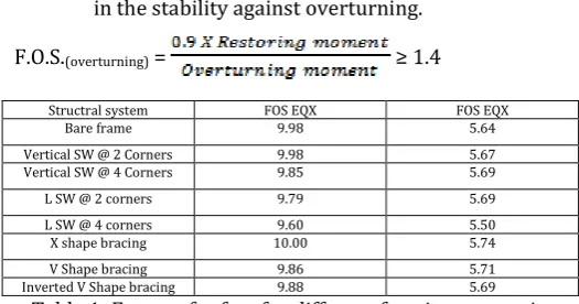
Stability Calculation for Overturning
In the high rise multi-storey buildings, we have to check the Stability of the building in terms of Factor of safety against Overturning. If the building height is more, the reaction due to dead loads occurs at bottom of the building also increases. If the dead loads decreases, the restoring moment with respect to horizontal directions will be less compare to overturning moment, then the structure may get fails
in the stability against overturning.
F.O.S.(overturning) = ≥ 1.4
Structral system FOS EQX FOS EQX
Bare frame 9.98 5.64
Vertical SW @ 2 Corners 9.98 5.67
Vertical SW @ 4 Corners 9.85 5.69
L SW @ 2 corners 9.79 5.69
L SW @ 4 corners 9.60 5.50
X shape bracing 10.00 5.74
V Shape bracing 9.86 5.71
[image:6.595.302.565.325.463.2]Inverted V Shape bracing 9.88 5.69
Table 1: Factor of safety for different framing system in zone III
we can observe that values obtained for Factor of safety along X and Y direction in zone 3 are not less than 1.4 hence all structural framing systems are stiff and rigid. Due to more shear walls the stiffness is more when L shape shear wall provided at 4 corners of the building. As the stiffness increases, time period decreases and factor of safety against overturning increases.
3. CONCLUSIONS
© 2016, IRJET | Impact Factor value: 4.45 | ISO 9001:2008 Certified Journal
| Page 1494
frequency decreases & also wave length increases.Hence system with less time period gives high stiffness value.
2. Because of high flexibility in normal framing system storey displacement is more as compare to high stiffness (rigid) by the provision of shear wall especially L-Shape shear wall at 4 corners. 3. Storey drift is the displacement of two stories to height of one storey, hence Storey drift is the function of lateral displacement. If the number of stories increases, lateral displacement increases, similarly storey drift also increases. When building provided with L-Shape shear wall at 4 corners less storey drift can be observed because displacement is less.
4. Storey drift for all models in different structural framing systems are within the permissible limits as per IS 1893 (Part-1): 2002, clause 7.11.1, i,e,. (0.004
x h) or ( ), h is storey height.
5. Factor of Safety against Overturning is for all different structural framing system are greater than 1.4, hence all systems are within permissible limits as per clause 20.1 of IS 456 : 2000, i.e., F.O.S.(overturning) ≥ 1.4. Hence systems are stiff enough to resist lateral. Due to the provision of L-shape shear wall, the stiffness is more.. As the stiffness increases, time period decreases and factor of safety against overturning increases.
REFERENCES
[1]
P. S. Pajgade and P. P Chandurkar, “Seismic Analysis ofRCC Building with and Without Shear Wall”, International Journal of Modern Engineering Research(IJMER) www.ijmer.com Vol. 3, Issue. 3, May - June 2013 pp-1805-1810
[2] O. Esmaili1 S. Epackach “Study of Structural RC Shear Wall System in a 56-Story RC Tall Building”, The 14th World
Conference on Earthquake Engineering October 2008, Beijing, China.
[3] N. Janardhana Reddy1, D. Gose Peera “ Seismic Analysis of Multi-Storied Building with Shear Walls Using ETABS-2013”, International Journal of Science and Research (IJSR)- November 2015
[4] Abbas Ali Ibrahim and Dr. N. V. Ramana Rao, “A Comparative Study between the Use of Framed Shear Wall System and Framed Tube System in Tall Buildings
[5] Lakshmi K.O and Prof. Jayasree Ramanujan, “Effect of shear wall location in buildings subjected to seismic loads”, ISOI Journal of Engineering and Computer science http://iosi.in/index.php/iosijecs-Dec. 2014
[6] Ashwinkumar Balaso Karnale and Dr. D. N. Shinde “Comparative Seismic Analysis of High Rise and Low Rise RCC Building with Shear Wall International Journal of Innovative Research in Science, Engineering and Technology-September 2015
[7] Prof. S.S. Patil, and Miss. S.A. Ghadge “ Seismic Analysis of High-Rise Building by Response Spectrum Method”, International Journal Of Computational Engineering Research, www.ijceronline.com- March-2013
[8] Ashish [14] IS 1893(Part 1):2002 “Criteria For Earthquake Resistant Design of Structures” BIS, New Delhi [9] Bureau of Indian Standard, IS-456(2000), “Plain and Reinforced Concrete Code of Practice”.
[10] Pankaj Agarwal and Manish Shrikande “Earthquake Resistant Design Of Structures” PHI Learning Private Limited New Delhi 2010
[11] IS : 875 (Part 2) – 1987 (Reaffirmed 2008), “Code of practice for design loads for buildings and structures. Part 2- Imposed load”.