Design optimization of Reversible Logic Universal
Barrel Shifter for Low Power applications
Ravish Aradhya H.V
Department of E and C, R V college of Engineering,
Bangalore 560059, India.
Lakshmesha J
Department of E and C, R V college of Engineering,Bangalore 560059, India.
Muralidhara K.N
Department of E and C, P E S college of Engineering
Mandya 571 401, India.
ABSTRACT
Applications such as address generation, encoding, decoding, data shifting, etc are of primary importance in many computing and processing applications. Design of Barrel shifters therefore demands more attention and the advent of quantum computation and reversible logic, design and implementation of all sub-systems in reversible logic has received more attention.Moore‟s law in VLSI designs today is no more a simple reality, the device dimensions are shrinking exponentially and the circuit complexity is growing exponentially. Various low power design techniques are proposed and successfully achieved. Device scaling is limited by the power dissipation; and demands better power optimizations methods. Techniques like Energy recovery, Reversible Logic are becoming more and more prominent special optimization techniques in Low Power VLSI designs. Reversible logic opens tremendous avenues for power optimizations in the areas such as Quantum Computing, Nanotechnology, Sprintronics and Optical Computing. Reversibility plays an important role when energy efficient computations are to be designed.
The objective of this work is to design a Universal Reversible Barrel Shifter that performs shifting left, right, rotates left and right. The performance characteristics of the existing design and the proposed design are compared with respect to transistor cost, Garbage outputs and Quantum Cost. The performance characteristics analysis is carried out in cadence digital design environment and CMOS implementation in cadence virtuoso.
General Terms
Address generation, Barrel Shifters, Feynman Gate, Fredkin Gate, Low Power designs, Power Optimization, Quantum computing, Reversible computing.
Keywords
Garbage output, Nanotechnology, Quantum Cost, Reversible, RLM Gate, Spintronics, Universal Reversible Barrel Shifter.
1.
INTRODUCTION
1.1
Motivation
1.1.1
Need for Low-power, area-efficient design
The need for low power, area-efficient and design is motivated by several factors, such as the emergence of portable systems, thermal considerations, reliability issues, and, finally, environmental concerns.
The evolution of portable or mobile communication devices such as laptops, cellular phones, video games, etc. is the most important factor driving the need for low power design. The main reason behind the development of low power circuits is that many portable devices and their applications require low power dissipation and high throughput. The commercial success of portable or mobile devices depends significantly on their weight, cost, and battery life. In most cases, the cost and weight of batteries become a bottleneck that prevents the reduction of system cost and weight. Moreover, for most portable systems, the IC components consume a significant portion of the total system power. Portable devices have a strict demand for power consumption since they have limited battery capacity. Low power design also plays a significant role in high-performance integrated circuits such as microprocessors and other high-speed digital computational circuits. Due to the increase in clock frequency, there is a proportional increase in power dissipation. The power consumed by the integrated circuit is dissipated in the form of heat. This may lead to problems such as circuit degradation and operating failures. The power consumption in microprocessors is projected to grow linearly in proportion to their die size and clock frequency. Various cooling systems have been introduced to reduce the heat from power dissipation and keep the chip temperature at an admissible level. This in turn has increased the packaging cost, which results in large revenue.
1.1.2
Reversible computing
circuits do not lose information. In reversible logic there is one-to-one mapping between the input and output vectors and vice-versa. Reversible logic has applications in several technologies such as nanotechnology, DNA computing, low power design, optical computing, Spintronics and quantum computing.
1.2
Barrel shifters
In DSP, where multiple shifts are required to do the computations such as FFT, circular convolution etc. barrel shifters are used to produce multiple shifts in only on clock cycle. For a reversible DSP system, barrel shifter also needs to be designed using reversible gates.
2.
LITERATURE SURVEY
Physical limitations placed on computation by heat dissipation were studied for many years. The usual digital computer program frequently performs operations that seem to throw away information about the computer's history, leaving the machine in a state whose immediate predecessor is ambiguous [1]. Such operations include erasure or overwriting of data, and entry into a portion of the program addressed by several different transfer instructions. In other words, the typical computer is logically irreversible - its transition function (the partial function that maps each whole-machine state onto its successor, if the state has a successor) lacks a single-valued inverse.
Landauer [1] has raised the question of whether logical irreversibility is an unavoidable feature of useful computers, arguing that it is, and has demonstrated the physical and philosophical importance of this question by showing that whenever a physical computer throws away information about its previous state it must generate a corresponding amount of entropy. Therefore, a computer must dissipate at least kTln2
of energy (about 3 X 10-21 joule at room temperature) for each bit of information it erases or otherwise throws away. At this point of time Bennett [2] showed: An irreversible computer can always be made reversible by having it save all the information it would otherwise throw away. For example, the machine might be given an extra tape (initially blank) on which it could record each operation as it was being performed, in sufficient detail that the preceding state would be uniquely determined by the present state and the last record on the tape. However, as Landauer pointed out, this would merely postpone the problem of throwing away unwanted information, since the tape would have to be erased before it could be reused. It is therefore reasonable to demand of a useful reversible computer that, if it halts, it should have erased all its intermediate results, leaving behind only the desired output and the originally furnished input. (The machine must be allowed to save its input-otherwise it could not be reversible and still carry out computations in which the input was not uniquely determined by the output.) General-purpose reversible computers (Turing machines) satisfying these requirements indeed exist, and they need not be much more complicated than the irreversible computers on which they are patterned. Computations on a reversible computer take about twice as many steps as on an ordinary one and may require a large amount of temporary storage.
While designing reversible system, the designer has to keep track of constraints [3]: only one fan-out is allowed and loops are not permitted.
A circuit is said to be reversible if the input vector can be uniquely recovered from the output vector and there is a one to one correspondence between its input and output assignments [8].Thus, the number of inputs and outputs in reversible logic circuits are equal. Reversible circuits allow the reproduction of the inputs from the observed [2]. Data shifting and rotating is often used operation , in this regard, barrel shifters which are capable of performing n-bit shifting and rotating of data in a single cycle, are normally used in embedded processors such as: digital signal processors [4] and high performance processors [5], high-speed/low-power applications [6] etc. The paper [7] shows the implementation of a reversible unidirectional barrel shifter and the second paper [9] shows the optimization of the same.
3.
DESIGN METHODOLOGY
3.1
Basic reversible gates
[image:2.595.338.516.306.374.2]Reversible gate: For a gate to be reversible the input and output should be one to one mapped (bijective) [2]. For instance Feynman gate has two inputs and two outputs; which are one to one mapped as in the Figure 1.
Figure 1: Feynman Gate and its input and output relation.
In the process of designing a reversible system, using reversible gates, certain unused outputs are produced which are called as Garbage Outputs. Garbage outputs are unavoidable but can be reduced.
Feynman Gate: Reversible 2*2 Feynman Gate (FE), its input and output logic relation is in the Figure 1. Feynman Gate is used in the scenario when it‟s required to produce multiple copies of an input signal, since only one fan-out is allowed in reversible logic gate [3].
Fredkin gate: Reversible 3*3 Fredkin gate (FR), its input and output logic relation is in the Figure 2. FG can be used as a 2*2 multiplexer.
Figure 2: Fredkin Gate and its input and output relation.
[image:2.595.319.539.562.629.2]
Figure 3: RLM Gate - Proposed Reversible gate
A logic synthesis technique using reversible gate should have the following features:
1. Use minimum number of garbage outputs. 2. Use minimum input constants.
3. Keep the length of cascading gates minimum.
4. Use minimum number of gates.
5. Minimize the quantum cost of the circuit.
3.2
Shifting using logarithmic shifters
.A barrel shifter is a digital circuit that can shift a data word by a specified number of bits in one clock cycle. It can be implemented as multiple stages of multiplexers (mux.), and in such an implementation the output of one mux is connected to the input of the next mux in a way that depends on number of shifts. The number of shift control bits is given by n = log N, where N is number of bits and D is shift direction control.
Figure 4: Barrel shifter implementation using logarithmic stages of 2k-shifters.
A logarithmic barrel shifter is usually implemented by cascading parallel 2×1 multiplexers. For a 4-bit Barrel shifter,
an intermediate signal is used which shifts by two bits, or passes the same data, based on the value of S[1]. This signal is then shifted by another multiplexer, which is controlled by S[0], the direction of the shift is controlled by the bit D.
Figure 5: Bi-directional Barrel shifter block diagram
S [1] and S [2] right shift control bits.
D is the direction control bit for left / right shift. D=1 right shift and rotate.
D=0 left shift and rotate. Out[3:0] is the output.
[image:3.595.318.533.131.226.2]The block diagram of Reversible Bidirectional Barrel Shifter is shown in Figure 5, i[3:0]-the inputs, o[3:0]-the outputs, D-direction controller and s[1:0]-select signals . The function table for input combination i[3:0] =1101 is as given in the Table 1.
Table 1: Function table of the proposed design
3.3
Existing left shift/rotate barrel shifter
The existing shifters in [4] and [5] are limited in terms of their incomplete universality and the unidirectional logarithmic shifter use multiplexers (Fredkin gate) and Feynman Gatefor replicating the inputs.
D S[1] S[0] Out[3] Out[2] Out[1] Out[0] 0 0 0 1 1 0 1 0 0 1 1 0 1 1 0 1 0 0 1 1 1 0 1 1 1 1 1 0 1 0 0 1 1 0 1 1 0 1 1 1 1 0 1 1 0 0 1 1 1 1 1 1 1 0 1 1
i [3:0]
D out[3:0]
S [1:0]
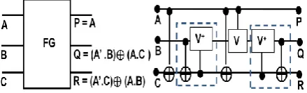
R = A⊕ CRLM Gate
P = A A
C
[image:3.595.63.282.436.713.2] [image:3.595.327.549.497.690.2]3.4
Proposed Universal Barrel Shifter
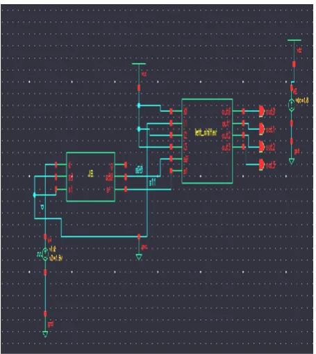
The proposed barrel shifter shown in Figure 6 can shift and rotate in both the directions. This enhancement is due to the new additional gate named as RLM gate (instantiated as JB in Figure 7) which manipulates the control bits „s0‟ and „s11‟ depending upon the value of direction control bit „d‟.
Figure 6: Proposed universal Reversible Barrel Shifter
4.
IMPLEMENTATION AND RESULTS
The proposed design is functionally verified and the results are compared with existing [4], [5] (as indicated in Figures 8 through 14).
[image:4.595.56.272.144.311.2]The area, average power and timing report was obtained after obtaining the netlist for the structural model of the digital implementation. The transistor cost was found in analog flow. Functionality was verified in both analog and digital flow. The universal barrel shifter is built by adding the RLM reversible gate and the verification results are as follows.
Figure 7: Schematic of proposed Reversible Barrel Shifter, s=00
4.1
Design implementation and simulation
in cadence virtuoso.
The schematic shown in the Figure 7 is a test circuit for input combination S=00, a square wave is applied to„d‟ to test for both the directions. Similar test circuits were built for other combinations and the results were verified for its functionality.
4.2
Design implementation and simulation
in cadence digital design
[image:4.595.314.542.244.649.2]For the HDL structural design, the test vectors for excitation has been provided, and the response is as shown in Figure 8. Here the input reference vector is i=1101.
Figure 8: A 4-bit bi-directional barrel shifter simulation result for s= {00, 01,10, 11} and d={0,1}
4.2.1 Synthesis
[image:4.595.55.283.468.723.2]Figure 9: Synthesized block of Proposed Reversible Barrel Shifter
4.3 Area report
The Area report for the existing design [5] and the proposed designs are generated and listed in Tables 2 and 3.
4.3.1 Area Report of existing design.
Generated by: Encounter(R) RTL Compiler v08.10-s121_1 (Oct 6 2008)
Generated on: Dec 24 2011 11:39:59
Module: reversible_barrel_shifter
Technology library: gscl45nm
Operating conditions: typical (balanced_tree)
Wireload mode: enclosed
Table 2: Area (um2) of Existing design
Instance Cells Cell
Area Net Area
Total Area
reversible_barre_shifter 46 163.91 0.00 163.91
reversible_barre_shifter/fe1 1 3.81 0.00 3.81
reversible_barre_shifter/fe2 1 3.81 0.00 3.81
reversible_barre_shifter/fe3 1 3.81 0.00 3.81
reversible_barre_shifter/fe4 1 3.81 0.00 3.81
Instance Cells Cell
Area Net Area
Total Area
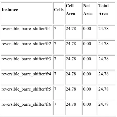
reversible_barre_shifter/fr1 7 24.78 0.00 24.78
reversible_barre_shifter/fr2 7 24.78 0.00 24.78
reversible_barre_shifter/fr3 7 24.78 0.00 24.78
reversible_barre_shifter/fr4 7 24.78 0.00 24.78
reversible_barre_shifter/fr5 7 24.78 0.00 24.78
reversible_barre_shifter/fr6 7 24.78 0.00 24.78
4.3.2 Area Report of proposed design
Generated by: Encounter(R) RTL Compiler v08.10-s121_1 (Oct 6 2008)
[image:5.595.313.546.70.302.2] Generated on: Dec 24 2011 11:59:05
Table 3: Area (µm2) of proposed design
Instance Cells Cell Area Net Area Total Area
reversible_barrel_shifter 52 184.88 0.00 184.88
reversible_barrel_shifter/fe1 1 3.81 0.00 3.81
reversible_barrel_shifter/fe2 1 3.81 0.00 3.81
reversible_barrel_shifter/fe3 1 3.81 0.00 3.81
reversible_barrel_shifter/fe4 1 3.81 0.00 3.81
reversible_barrel_shifter/fr1 7 24.78 0.00 24.78
reversible_barrel_shifter/fr2 7 24.78 0.00 24.78
reversible_barrel_shifter/fr3 7 24.78 0.00 24.78
reversible_barrel_shifter/fr4 7 24.78 0.00 24.78
reversible_barrel_shifter/fr5 7 24.78 0.00 24.78
reversible_barrel_shifter/fr6 7 24.78 0.00 24.78
Module: reversible_Bi_direcitonal_barrel_shifter
Technology library: gscl45nm
Operating conditions: typical (balanced_tree)
Wireload mode: enclosed
4.4 Power report
The power report for the existing design [5] and the proposed designs are generated and listed in Tables 4 and 5.
4.4.1 Power Report of existing design
Generated by: Encounter(R) RTL Compiler v08.10-s121_1 (Oct 6 2008)
Generated on: Dec 24 2011 11:39:47
[image:6.595.53.284.319.752.2] Module: reversible_barrel_shifter
Table 4: Power of Existing design
Instance Cells Leaka ge (nW) Intern al (nW) Net (nW) Switchi ng (nW) reversible_barrel_shift
er 46
243.7 3
3150. 19
2919.
12 6069.32
reversible_barrel_shift
er/fe1 1 12.04 185.1
6 0.00 185.16
reversible_barrel_shift
er/fe2 1 12.04 185.16 60.50 245.66
reversible_barrel_shift
er/fe3 1 12.04 185.16 60.50 245.66
reversible_barrel_shift
er/fe4 1 12.04 185.1
6 60.50 245.66
reversible_barrel_shift
er/fr1 7 32.60 375.6 8
302.5
0 678.18
reversible_barrel_shift
er/fr2 7 32.60 388.1 1
294.9
4 683.04
reversible_barrel_shift
er/fr3 7 32.60 374.00 264.69 638.68
reversible_barrel_shift
er/fr4 7 32.60 361.57 257.12 618.69
reversible_barrel_shift
er/fr5 7 32.60 431.1 0
302.5
0 733.60
reversible_barrel_shift
er/fr6 7 32.60 479.1 3
347.8
8 827.01
Technology library: gscl45nm
Operating conditions: typical (balanced_tree)
Wireload mode: enclosed
4.4.2 Power Report of proposed design
Generated by: Encounter(R) RTL Compiler v08.10-s121_1 (Oct 6 2008)
Generated on: Dec 24 2011 12:00:01
Module: reversible_bi_direcitonal_barrel_shifter
Technology library: gscl45nm
Operating conditions: typical (balanced_tree)
Wireload mode: enclosed
Table 5: Power of Proposed design
Instance Cells Leakage (nW) Intern al (nW) Net (nW) Switchi ng (nW) reversible_barrel_shift
er 52 284.98 4390. 76
3682.
94 8073.69
reversible_barrel_shift
er/fe1 1 12.04 185.16 0.00 185.16
reversible_barrel_shift
er/fe2 1 12.04 185.16 60.50 245.66
reversible_barrel_shift
er/fe3 1 12.04 185.1
6 60.50 245.66
reversible_barrel_shift
er/fe4 1 12.04 185.1
6 60.50 245.66
reversible_barrel_shift
er/fr1 7 32.60 375.6 8
302.5
0 678.18
reversible_barrel_shift
er/fr2 7 32.60 388.11 294.94 683.04
reversible_barrel_shift
er/fr3 7 32.60 374.00 264.69 638.68
reversible_barrel_shift
er/fr4 7 32.60 361.5 7
257.1
2 618.69
reversible_barrel_shift
er/fr5 7 32.60 573.4 9
400.8
1 974.30
reversible_barrel_shift
er/fr6 7 32.60 619.68 453.75 1073.43
reversible_barrel_shift
4.5 Timing report
[image:7.595.57.288.124.337.2]The Timing report for the existing design [5] and the proposed designs are generated and shown in Figures 10 and 11.
[image:7.595.313.549.310.470.2]Figure 10: Timing report of the Existing Reversible Barrel Shifter [5]
Figure 11: Timing report of the proposed Reversible universal Barrel Shifter
The maximum, which is the worst case delay from input to the output pin, is shown in the Figures 10 and 11. The Figure 10 and 11 show only the pins in the critical path.
4.6 Summary of the results
The performance contrast of the prior and the proposed barrel shifter design is tabulated as in table 6. From the table 6 it is evident that that the proposed design offers additional functionality of bidirectional shifting and rotation with
[image:7.595.58.280.376.604.2]16.55% increased delay, 24.47% increased power consumption and with 11.34% increased area.
Table 6: Performance contrasts of Existing and Proposed Barrel Shifter designs
Existing Design2 Proposed Design
Average Power 12.38 µw 16.39 µw
Area 163.91 µm2 184.88 µm2
Delay(critical path)
256.1 ps 306.9 ps
[image:7.595.316.538.543.691.2]The reversible parameter contrast of the prior and the proposed barrel shifter designs is shown in Table 7.
Table 7: Reversible logic parameter contrasts of Existing designs and proposed design
Summarizing, the bi-directional functionality has been realized with reduced costs. Only at a marginal increase in the costs, both performance and universality are realized; this is indicated in Figure 12.
Figure 12: Cost comparison between existing and proposed designs
0 50 100 150 200 250 300 350
400 Design in[4]
Design in [5]
Proposed Design
Existing Designs (Unidirectional)
Proposed Design
(Universal) ED-1:[4] ED-2:[5]
Gate count 24 10 11
Garbage outputs 14 6 7
Quantum cost 72 34 53
Transistor cost 376 276 306
5.
RLM ALGORITHM FOR N-BIT
REVERSIBLE
BIDIRECTIONAL
BARREL SHIFTER
A new algorithm for design an N-bit barrel shifter that offers a unique advantage of only one Garbage Output (GO) for all N values is proposed here. This not only offers constant GO of one, but also offers area and power optimization.
i.
Design an N-bit barrel shifter for left or right shift and rotate.N-bit (4, 8, 16, 32...) Barrel shifter with inputs i0, i1...iN-1 and
shifted outputs o0,o1,……oN-1requires”n”shift control bits
c0,c1,….cn-1where „n‟ is given by Eq. 5.1.
n = log2N ………. Eq. 5.1
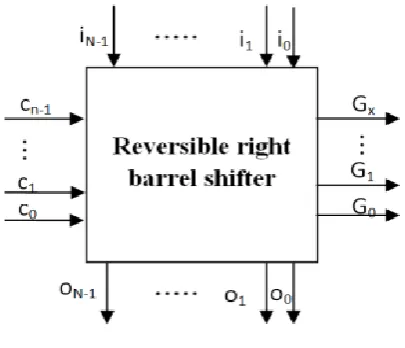
These shift control bits decide number of shifts for the data. This Reversible circuit produces more number of garbage outputsG0, G1,…..Gx.For instance consider a reversible right
[image:8.595.372.506.75.176.2]barrel shifter Figure 13.
Figure 13: Reversible right barrel shifter
In order to optimize the performance of the circuit, the number of garbage outputs need to be reduced; this in turn reduces the area, power dissipation of the circuit.
ii. The number of garbage outputs may be reduced to 1 always irrespective of the size of the Shifter. In order to achieve this, a new control gate called as RLMn gate is proposed as shown in Figure 14. Design the RLMn Gate reversible control gate, by adding another control signal „D„ for direction control (left/right). The RLMn Gate maps the inputs d, sn-1...s1, s0to
outputs G, cn-1...c1, c0as shown in Figure 14.Here, G is the
only garbage output and cn-1...c1, c0 are the new control
[image:8.595.70.273.335.509.2]outputs.
Figure 14: Reversible RLM Gate shift control gate.
Let d= 0 for right circular shift. S0
1 for left circular shift.
The garbage output G is given by Eq. 5.2 for all the sizes of shift register. The garbage output is used to make the RLMn Gate bijective (one to one mapping). RLMn Gate hence produces only one garbage output for all the cases irrespective of size of the shift register.
G = d ⊕S0 ………. Eq. 5.2
The truth table formulation: For d=0, (cn-1...c1, c0) = (s n-1...s1, s0). For d=1 i.e for opposite direction, mirror the
input control sequence around the N+(N/2)+1 vector as shown in Table 8.
[image:8.595.338.543.437.723.2]Hence, determine the input output relationship by using the CAD tool or manually using Eq. 5.3.x
c0= f(d, sn-1...s1, s0) …………. Eq. 5.3.1
c1= f(d, sn-1...s1, s0) …………. Eq. 5.3.2
.
.
cn-1= f(d, sn-1...s1, s0) …………. Eq. 5.3.n
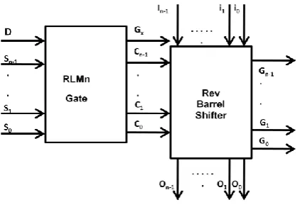
[image:9.595.64.277.295.441.2]iii. Finally, integrate the reversible N-bit reversible shifter with designed RLM gate as in Figure 15.
Figure 15: Final integrated reversible N-bit barrel shifter.
6.
CONCLUSIONS
AND
FUTURE
WORK
The existing unidirectional and new bi-directional reversible barrel shifter designs have been designed and verified for its functionality in cadence digital flow (using gscl45nm
technology library) and also in cadence analog flow (using
gpdk180 technology library). The proposed barrel shifter can shift and rotate in both left and right directions. The additional new RLM gate offers bi-directional functionality with only a marginal increase in the overheads such as quantum cost, garbage outputs, gate count and delay. The present design is of 4-bit size, similar design methodology can be used to design 8-bit and higher reversible barrel shifters. Many barrel shifter designs have been produced but nevertheless the designs are not impeccable. Hence there is always a scope to enhance the design; further optimization can be achieved by reducing the overheads.
7.
REFERENCES
[1] Rolf Landauer, "Irreversibility and Heat Generation in the Computing Process," IBM Journal of Research and Development, vol. 5, July-1961, pp. 183-191.
[2] C.H. Bennett , “Logical Reversibility of Computation”,
IBM Journal of Research and Development, pp. 525-532, November 1973
[3] C.H. Bennett, "Notes on the History of Reversible Computation", IBM Journal of Research and Development, vol. 32, No.1, Jan-1998, pp. 16-23. [4] Gorgin S, Kaivani A, “Reversible Barrel Shifters,”
IEEE/ACS International Conference on Computer System and applications, Vol.07, Issue, 13-16 May 2007, pp. 479 – 483.
[5] Irina Hashmi and Hafiz Md. Hasan Babu, “An Efficient Design of a Reversible Barrel Shifter,” 23rd International Conference on VLSI Design, 2010, pp.93-98.
[6] Sabyasachi Das and Sunil P. Khatri, “A Timing-Driven Approach to Synthesize Fast Barrel Shifters”, IEEE Transactions on circuits and systems—ii: express briefs, vol. 55, no. 1, January 2008, pp. 31-35.
[7] Horacio C. Neto and Mario P. Vestias, “Architectural trade-offs in the design of Barrel Shifters for reconfigurable computing”, IEEE Explore, 2008, pp.31-36.
[8] Mathew R. Pillmeier, Michael J. Schulte and E. GeorgeWaltersIII, “Design alternatives for barrel shifters”, Computer Architecture and Arithmetic Laboratory, Computer Science and Engineering Department, Lehigh University, Bethlehem, PA 18015,USA.
[9] Saurabh Kotiyal, Himanshu Thapliyal and Nagarajan Ranganathan, “Design of a Ternary Barrel Shifter Using Multiple-Valued Reversible Logic”, 10th IEEE
international conference on Nanotechnology, Seoul, Korea, August 2010, pp.1104-1108.
[10] Saurabh Kotiyal, Himanshu Thapliyal and Nagarajan Ranganathan, “Design of a Reversible bidirectional Barrel Shifter”, 11th IEEE international conference on
Nanotechnology, Portland, Oregon, August 2011, pp.463-468.
[11] Prasad D Khandekar, Shaila Subbaraman and Venkat Raman Vinjamoori, “Quasi-Adiabatic 2X2 f Shifter”, 4th
international conference on Industrial and Information systems ICIIS-2009, 28-31 December 2009, pp.321-324. [12] Peter A. Beerel, Sangyun Kim, Pei-Chuan Yeh,
Kyeounsoo Kimt, “Statistically Optimized Asynchronous Barrel Shifters for Variable Length Codecs”, ACM Journal, 1999, pp. 261-263.
![table for input combination i[3:0] =1101 is as given in the](https://thumb-us.123doks.com/thumbv2/123dok_us/8124111.795024/3.595.63.282.436.713/table-input-combination-i-given.webp)