© 2018, IRJET | Impact Factor value: 6.171 | ISO 9001:2008 Certified Journal | Page 3173
POWER QUALITY IMPROVEMENT IN GRID CONNECTED WIND ENERGY
SYSTEMS USING STATCOM
Anagha Suresh M
1, Anjali VC
2, Arathi P
31,2,3 Student, Dept. of Electrical and Electronics Engineering, Mar Athanasius college of Engineering,
Kothamangalam, Kerala, India
---***---Abstract
–
The demand for energy have been increasingday by day, so the need for energy generating systems. Conventional methods are becoming threat to the environment and could not replenish quickly. So the use of renewable energy resources is trending nowadays. Wind energy systems are used in remote areas where electricity is hard to establish with conventional methods. But there are some power quality issues related with the wind energy systems. So in order to reduce these, Flexible Alternate Current Transmission System (FACTS) devices are used. Of that, the most efficient one is STATCOM. FACTS devices provide smooth and proper integration of wind energy system to the grid.
Furthermore, the detailed investigations using
MATLAB/SIMULINK is explored in this project for the enhancement of power quality using STATCOM, integrated with battery energy storage system. The STATCOM model is tested using a hardware setup.
Key Words: Wind turbines, FACTS, STATCOM, Voltage flicker, Harmonics, Arduino, Pulse Width Modulated inverter
1.INTRODUCTION
Wind is the natural movement of air across the land or sea. Wind is caused by uneven heating and cooling of the earth's surface and by the earth's rotation. Land and water areas absorb and release different amount of heat received from the sun. As warm air rises, cooler air rushes in to take its place, causing local winds. The rotation of the earth changes the direction of the flow of air. Wind power is the fastest growing source of energy in the world. If you have enough wind resource in your area and the situation is right, small wind electric systems are one of the most cost-effective home-based renewable energy systems with zero emissions and pollution. A country like India or any region where energy production is based on imported coal or oil will become more self-sufficient by using alternatives such as wind power. Electricity produced from the wind produces no
CO2 emissions and therefore does not contribute to the
greenhouse effect. Wind energy is relatively labor intensive and thus creates many jobs. In remote areas or areas with a weak grid, wind energy can be used for charging batteries or can be combined with a diesel engine to save fuel whenever wind is available. At windy sites the price of electricity, measured in Rs/kWh, is competitive with the production price from more conventional methods, for example coal fired power plants.his document is template.
1.1 Wind Farms
A wind farm is a group of wind turbines in the same location used to produce electricity. A large wind farm may consist of several hundred individual wind turbines and cover an extended area of hundreds of square miles, but the land between the turbines may be used for agricultural or other purposes. A wind farm can also be located offshore. Usually sites are screened on the basis of a wind atlas and validated with wind measurements. Meteorological wind data alone is usually not sufficient for accurate siting of a large wind power project. Collection of site specific data for wind speed and direction is crucial to determining site potential in order to finance the project. Local winds are often monitored for a year or more, and detailed wind maps constructed before wind generators are installed
1.2 Power Quality Issues
The term "power quality" refers to the voltage stability, frequency stability, and the absence of various forms of electrical noise (e.g. flicker or harmonic distortion) on the electrical grid. More broadly speaking, power companies (and their customers) prefer an alternating current with a nice sinusoidal shape.
Flicker is an engineering expression for short lived voltage variations in the electrical grid which may cause light bulbs to flicker. This phenomenon may be relevant if a wind turbine is connected to a weak grid, since short-lived wind variations will cause variations in power output. There are various ways of dealing with this issue in the design of the turbine, mechanically, electrically, and using power electronics.
Islanding is a situation which may occur if a section of the electrical grid becomes disconnected from the main electrical grid, e.g. because of accidental or intended tripping of a large circuit breaker in the grid (e.g. due to lightning strikes or short circuits in the grid). If wind turbines keep on running in the isolated part of the grid, then it is very likely that the two separate grids will not be in phase after a short while.
© 2018, IRJET | Impact Factor value: 6.171 | ISO 9001:2008 Certified Journal | Page 3174
box and the rotor of the wind turbine) much like "hard switching" the turbine generator onto the grid would do.
If a turbine is connected to a weak electrical grid, (i.e. it is very far away in a remote corner of the electrical grid with a low power-carrying ability), there may be some brownout / power surge problems of the sort mentioned above. In such cases it may be necessary to reinforce the grid, in order to carry the fluctuating current from the wind turbine.
Harmonics are the most common power quality issues presented by large Wind power plants because of the high switching frequency of the power converters and the possible nonlinear behavior from electric machines
(generator, transformer, reactors) within a power plant.
1.3 Power Quality Improvement
The FACTS controllers are mainly based on power electronic controllers that enhances the transferring ability of the line. The power electronic controllers are fast in response and increases the stability limits of the power transmission systems when their associated controllers are properly controlled. The FACTS controllers are mainly used to normalize terminal voltage and control power flow through the transmission lines. In STATCOM by connecting power electronic switches and switching them at exact angles within each 50 Hz cycle an accurate sinusoidal waveform is developed. If the generated voltage in this method is higher than terminal voltage the compensator will supply reactive power as that of synchronous condenser and improve the voltage level and conversely, if lower, it will remove reactive power from the system. The proposed STATCOM has the potential to maintain its reactive current at low voltage since it has constant current characteristics while a thyristor SVC is constant impedance. The STATCOM proposed here can provide fast capacitive and inductive compensation. STATCOM has the ability to control its output current independent of the network voltage.
Fig - 1: Voltage Fluctuation Mitigation with STATCOM
Figure-1 shows the location of STATCOM to reduce voltage sag. Generally, STATCOM is effective shunt compensator used to maintain voltage profile constant. Here the compensator is connected between source and power transformer. The STATCOM regulates voltage at its terminal by controlling the amount of reactive power injected into or absorbed from the power system. When system voltage is low, the STATCOM generates reactive power (STATCOM
capacitive). When system voltage is high, it absorbs reactive power (STATCOM inductive).
2. BLOCK DIAGRAM
Fig - 2: Block diagram of STATCOM
Figure-2 represents the block diagram of static compensator with nonlinear load. Normally induction generator is used in wind energy generating units.
The basic blocks are described below:
1.Voltage source converter:
The voltage-source converter is used to convert the DC input voltage to an AC output voltage. Two of the common VSC types are as below.
a) Square-wave Inverters using Gate Turn-Off Thyristors :
In this type of VSC, output AC voltage is controlled by changing the DC capacitor input voltage, as the fundamental component of the converter output voltage is proportional to the DC voltage.
b) PWM Inverters using Insulated Gate Bipolar Transistors:
It uses Pulse Width Modulation (PWM) technique to create a sinusoidal waveform from a DC voltage source with a typical chopping frequency of a few kHz. In contrast to the GTO-based type, the IGBT-GTO-based VSC utilizes a fixed DC voltage and varies its output AC voltage by changing the modulation index of the PWM modulator.
2. Harmonic filter:
Harmonic Filter attenuates the harmonics and other high frequency components due to the VSC.
3.Transformer:
[image:2.595.307.555.114.297.2] [image:2.595.47.274.557.634.2]© 2018, IRJET | Impact Factor value: 6.171 | ISO 9001:2008 Certified Journal | Page 3175
medium. In addition, Transformer neutralizes harmonics contained in the square waves produced by VSC.
3. CIRCUIT DIAGRAM
Fig - 3: Circuit diagram
Figure-3 shows the circuit diagram of PWM sine wave inverter. It clearly reveals various connections to the Arduino board from various components such as PWM inverter, LCD display, potential divider. 7805IC acts as the voltage regulator and supplies 5V to Arduino microcontroller and LCD display. The input to the microcontroller is varied with potential divider.
Atmega 328p has been used for generating PWM switching sequence for the inverter where MOSFET plays the role of switching device. The output of PWM inverter is 12V AC which is stepped up using transformer. The transformer output is constant even if input is varied.
4.OBSERVATIONS AND RESULTS
4.1 Simulation Results
The simulation was done by using SIMULINK in MATLAB. Figure-4 depicts the SIMULINK model for a wind energy system using STATCOM. A distribution static synchronous compensator(D-STATCOM) is used to regulate voltage on a 25KV distribution network. Feeders(30km) transmit power to loads.
Fig - 4: Simulink model using STATCOM
Fig - 5: Effect on voltage for grid connected system with
STATCOM
Fig - 6:Effect on active and reactive power for grid
connected system with STATCOM
The reaction of the lively electricity injected into the network is low without STATCOM because no reactive energy assists in the community, because of insufficient reactive power reimbursement, WTIG machine stability is lost. The active electricity injected to the distribution network reduces considerably when a 3 phase fault is applied at t=3sec and cleared at 3.1sec. The reaction of the WTIG speed will increase, while a three segment fault is carried out. The system losses balance and the velocity of the WTIG maintains to growth. For the machine with STATCOM,
Active power
[image:3.595.305.556.58.396.2] [image:3.595.303.553.87.229.2] [image:3.595.46.278.140.332.2] [image:3.595.307.560.253.415.2] [image:3.595.308.562.462.607.2]© 2018, IRJET | Impact Factor value: 6.171 | ISO 9001:2008 Certified Journal | Page 3176
the steadiness of the system is maintained after the fault clearance due to reactive energy help, the WTIG terminal voltage is slightly accelerated at once after the fault clearance. So the system maintains stability and finally the WTIG terminal voltage recovers. So in order to increase the voltage the reactive power gets injected as a part of compensation by the STATCOM. Figure-5 and Figure-6 shows the output waveform of voltage and power when a fault was introduced and compensated.
4.2 Hardware Implementation
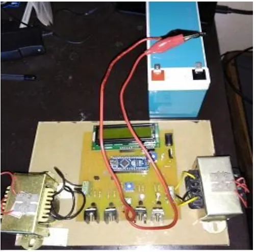
Figure-7 shows the hardware setup of a PWM sine wave inverter and output transformer. The components used in the hardware setup are Atmega 328p microcontroller, center tapped transformer 12-0-12, IRF640 MOSFET, LCM 162a LCD display, CTPN2222A BJT and 7805 voltage regulator IC.
Fig - 7: Hardware setup
The distortion caused by the nonlinear load and wind generator due to wind speed fluctuations are suppressed by the three phase injected currents. The required reactive power for compensation and the compensated current for nonlinear load are provided by the inverter. Whenever there happens a change in voltage at the input side, the output voltage remains constant. The input voltage is varied between 6V to 9V using a potential divider. Here we use PWM inverter in order to get constant output voltage with varying loads. The output gets compensated based on the change in the switching pulses width, this explains the principle of pulse width modulation. Due to practical limitations of using wind energy system from the grid, we are only presenting a part of the system, which includes only making the output voltage constant. As a purpose for further
enhancement we can provide a feedback network in order to enable compensation.
4.3 Results
Pulse Width Modulated sine wave inverter is implemented in hardware, which is shown in Figure-7. The required reactive power for compensation and the compensated current for nonlinear load are provided by the inverter.
The switching pulses for PWM inverter were provided by the microcontroller ATMEGA 328p. These pulses are shown in fig 4.5 and fig 4.6. The D10 pin gives the output as shown in fig 4.5 and D9 pin gives the output as shown in fig 4.6. Using these square pulses, inverter generates an output of 220V AC voltage from an input of DC. The input voltage is varied between 6V to 9V using a potential divider and it is observed that the output voltage remains constant at 220V.
Fig - 4.5: D10 pin output Fig - 4.6: D10 pin output
waveform waveform
5.CONCLUSIONS
In this project, STATCOM based control scheme for power quality improvement in grid connected wind generating system and with nonlinear load was studied. The power quality issues and its consequences on the consumer and electric utility were analyzed. The operation of the STATCOM in MATLAB/SIMULINK for maintaining the power quality is simulated. When fault was introduced in the system, it was observed that there was a fall in voltage but within seconds the change in voltage was compensated by the STATCOM. It has the capability to maintain the source voltage and current in phase and supports the reactive power demand for the wind generator and load at PCC in the grid system, thus it enhances the utilization factor of the transmission line. Due to certain limitations and matter of risk, the grid connected wind energy system and its compensation was beyond our limits to establish. Hence, a PWM inverter was implemented in the hardware part. Whenever there is a change in voltage at the input side, the output voltage remains constant.
ACKNOWLEDGEMENT
[image:4.595.37.288.294.541.2] [image:4.595.311.562.320.446.2]© 2018, IRJET | Impact Factor value: 6.171 | ISO 9001:2008 Certified Journal | Page 3177
First of all, we thank God Almighty for his blessings as it is only through his grace that we were able to complete our project successfully.
We take this opportunity to extend our sincere thanks to our project guide Dr.Siny Paul, and all the members of the Department of Electrical & Electronics Engineering for sharing their valuable comments during the preparation of the project.
We also extend our deep sense of gratitude to our Faculty Advisor Prof. Neena Mani, Assistant Professor, Electrical & Electronics Engineering Department for her creative suggestions during the preparation of the project.
We express our deep sense of gratitude to Prof. Acy M Kottalil, Head of Electrical & Electronics Engineering Department.
We are deeply indebted to Dr. Solly George, Principal, Mar Athanasius College of Engineering for her encouragement and support.
We whole - heartedly thank all our classmates, for their valuable suggestions and for the spirit of healthy competition that existed between us.
REFERENCES
[1] Sharad W.Mohod and Mohan V.Anware "A ST ATCOM
control scheme for grid connected wind energy system for power quality Improvement,"IEEE systems
journal,Vol.4,No.3 Sep.
[2] H.R. Naja_. "Transient Stability Evaluation of Wind
farms Implimented with Induction Generators",
International Universities Power Engineering
Conference
[3] Mohod.S.W and M. V. Aware, "Power quality issues & it's
mitigation technique in wind energy conversion," in Proc. of IEEE Int. Conf. Quality Power & Harmonic, Wollongong, Australia, 2008.
[4] Liu Lianguang."Simulation and Analysis of voltage sag
mitigation using active series voltage Injection",Power Conference 2000,lnternational Conference of Power