Mathematical Modelling of Roll Motion for a Floating
Body in Regular Waves Using Frequency Based Analysis
with Speed
Masoud Baghfalaki
1,
Samir K.
Das
2,*1Department of mathematics, Kermanshah branch, Islamic Azad University, Kermanshah, Iran 2Department of Applied Mathematics, Defence Institute of Advanced Technology (DIAT)
Deemed University, Girinagar, Pune-411025, India *Corresponding Author: [email protected]
Copyright © 2013 Horizon Research Publishing All rights reserved.
Abstract
This paper deals with the mathematical modelling and frequency-based analysis for uncoupled roll motions of a floating body in regular waves with the variation of speed. First we compute hydrodynamic coefficients by using strip theory formulation. Considering sinusoidal wave with frequency (
ω
) varying between 0.3 to 1.2 acts on beam to the floating body for zero and non-zero forward speed (U =0 and 12 m/s) governing equation is obtained. Using the normalization procedure and frequency based analysis; group based equations are formulated for each case. Based on relative importance of the hydrodynamic coefficients, analytical solutions are derived for zero and non-zero forward speed. The sensitivity analysis with respect to the effect of damping is also investigated. This study could be useful to understand the effect of waves on roll motion due to the variation of speed for various frequencies.Keywords
Roll, Hydrodynamic Coefficient, Froude-Krylov Force, Added Mass, Damping1. Introduction
Computation of ship motions and wave-induced loads assumes enormous importance in terms of initial stage of ship design, seaworthiness, stability and safety. Understanding roll and associated motion is important for efficient cargo-handling operation and passenger’s comfort. Cummins [1] first reported motion analysis in time domain using the impulse response function.Holappa and Falzarano [2] considered frequency dependent hydrodynamic coefficients for roll motions in time domain. Here, added mass and damping coefficients of the equations of motion is frequency dependent and the equations are solved for a discrete set of frequencies. In this paper, roll motion for single degree of freedom is modeled for obtaining the
behaviour of floating body in regular wave assuming the system is linear. Using the strip theory approach illustrated by Salvesen et al. [3] in concurrence with Tick’s [4] analysis, the sectional added mass and damping coefficients are integrated by applying the close fit method of Frank and Salvesen [5] based on the experimental results of Vugts [6]. Das and Das [7-10] developed analytical and numerical models in time domain corresponding to sway-roll-yaw (3-DOF) by considering zero or non-zero forward speed. Baghfalaki et al. [11] developed analytical models in frequency domain corresponding to roll-yaw motions (2-DOF) and obtained response amplitude operator (RAO). Subsequently, Baghfalaki and Das [12] developed RAO for roll motion in frequency domain and established analogy with free damped vibration. In this paper, we consider governing equation for roll motion in time domain and derive analytical solution for three cases and classify them for various frequencies.
2. Mathematical Formulation
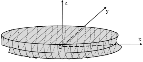
We consider a right-handed Cartesian system co-ordinate system (x, y and z) fixed with respect to the mean position of the floating body with origin O at the still water level and the z-axis is positive in vertical upward direction [Fig.1]. The floating body is assumed to be rigid and slender, symmetric about x-z plane and rests on undisturbed free surface. A floating body can exhibit motions of six degrees of freedom (6-DOF) under the action of waves. The wave induced motions of the body can be described as (i) translatory displacements along x, y and z directions, which are known as surge
(
η
1)
, sway(
η
2)
and heave(
η
3)
respectively, and (ii) angular displacements about the same set of axes are known as roll(
η
4)
, pitch(
η
5)
and yaw(
η
6)
equations: (i) the responses are linear and harmonic (ii) the floating body has lateral symmetry (iii) incident wave is sinusoidal in form (iv) force components generated by the propeller, wind and current are not considered. The equation of motion in frequency domain representing linearly coupled condition can be described as (Tick [4])
Figure 1. Schematic diagram of a floating body with sign convention
{
}
2 ( ) ( ) ( ) ( )i t
jk jk jk jk k
M A i B C X eω
ω ω ω ω ω ω
− + + +
( )
i tj j
D F
ω
e
ω
=
;j,k = 1,2 ,..,6 (1)where
M
jk , A
jk( )
ω
, B
jk( )
ω
, C
jk( )
ω
and( )
j
F
ω
are the matrix representation of the coefficients for
mass, added-mass, damping, restoring and wave force/moment respectively and
D
j is the wave amplitude for j th mode of motion. The added-mass and damping are determined by integrating the respective two-dimensional sectional coefficients along the length of the body, using new strip theory approach of Salvesan et al. [3]. The schematic diagram of strips is shown in Fig. 2. From (1), the governing equation for roll motion can be written asFigure 2. Schematic diagram of strips of a floating body 2
44 44 44 44 4 4 4
[−ω (M +A ( ))ω +i Bω ( )ω +C ( )] ( )ω X ω =D ( ) ( )ω F ω (2)
where
44 44 2 44
44 44 44
U A
A U
A a d b
B b d a
ζ
ω
ζ
= − = +∫
∫
(3)Here
a
44andb
44are the sectional added mass anddamping coefficients and the integrations are over the length of the ship. The roll restoring coefficient,
C
44
is given by44
C
=
ρ
g GM
∇
(4)where
∇
is the displaced volume of the floating body in calm water,GM
is the meta-centric height andρ
is the mass density of water. The wave exciting momentF
4( )
ω
can be expressed as (Salvesen et al. [3])
4 4 4 4 4 4
( )
(
)
(
)
A A AF
F sin t
U
F
f
h d
i
h
ω
ω ε
αρ
ξ αρ
ω
=
+
=
∫
+
+
(5)where
F
4A is the amplitude of the roll exciting moment corresponding to the wave encountering frequencyω
and phase angleε
. The integration has been performed over the length of the body;α
is the amplitude of the incident wave;4
f
and 4h
represent the sectional Froud-Krylov force and sectional diffraction force respectively corresponding to the wave encountering frequency (ω
). For zero forward speed, the terms containing U in (4) and (5) does not appear.3. Frequency Based Analysis
We define
x t
4( )
=
X
4( )
ω
e
i tω and f t4( )=F4( )ω
ei tω and substitute in (2), one can get4 4 44 44 4 44 4 44 4 ( )
(M +A ( )) ( )ω x t +B ( ) ( )ω x t C + ( ) ( )ω x t =D f t (6) Here the motion variables
x t
4( )
, exciting forcef t
4( )
and wave frequency (ω) described in (6) are complex quantities. However, we consider only the real part of motion response and exciting moment for a given wave frequency. After dividing by their corresponding leading coefficients (added mass / moment), the following equation for roll motion is obtained.
4
44 4
44 4
4 4
x
+
b x
+
c x
=
D f
(7)Where
44 44
/ (
44 44);
44 44/ (
44 44);
b
=
B
M
+
A
c
=
C
M
+
A
4 4
/ (
44 44)
f
=
f
M
+
A
(8) [image:2.595.64.294.495.595.2]Table 1. Normalized hydrodynamic coefficients
V=
0
ω 0.30 0.40 0.50 0.56 0.60 0.70 0.74 0.80 0.90 1.0 1.10 1.20
Case A (HC>1.0)
44
b Abs Abs Abs Abs Abs Abs Abs Abs Abs Abs Abs Abs
44
c Abs Abs Abs Abs Abs Abs Abs Abs Abs Abs Abs Abs
Case B (HC>0.1)
44
b Abs Abs Abs Abs Abs 0.11 0.15 0.16 0.17 0.18 0.15 0.14
44
c 0.43 0.42 0.42 0.42 0.43 0.45 0.48 0.50 0.53 0.55 0.56 0.56
Case C (HC>0.01)
44
b 0.07 0.06 0.05 0.08 0.09 0.11 0.15 0.16 0.17 0.18 0.15 0.14
44
c 0.43 0.42 0.42 0.42 0.43 0.45 0.48 0.50 0.53 0.55 0.56 0.56
4
f 0.01 0.02 0.03 0.04 0.04 0.04 0.04 0.05 0.05 0.04 0.04 0.03
== == == == == == == == == == == == == == == == == == == == == == == == == == == == == == == == == == == == == == == == == == == == == == == == == == == == == == == == == == == == == == == == ==
V
=1
2
ω 0.30 0.40 0.50 0.56 0.60 0.70 0.74 0.80 0.90 1.0 1.10 1.20
Case A (HC>1.0)
44
b Abs Abs Abs Abs Abs Abs Abs Abs Abs Abs Abs Abs
44
c Abs Abs Abs Abs Abs Abs Abs Abs Abs Abs Abs Abs
Case B (HC>0.1)
44
b Abs 0.10 Abs 0.12 0.13 0.15 0.19 0.20 0.21 0.19 0.18 0.17
44
c 0.43 0.42 0.42 0.42 0.43 0.45 0.48 0.50 0.53 0.55 0.56 0.56
Case C (HC>0.01)
44
b 0.08 0.10 0.09 0.12 0.13 0.15 0.19 0.20 0.21 0.19 0.18 0.17
44
c 0.44 0.44 0.42 0.43 0.44 0.46 0.49 0.51 0.53 0.49 0.56 0.57
Real part of f4 0.01 0.02 0.03 0.04 0.04 0.04 0.04 0.05 0.05 0.04 0.04 0.03
Frequency (ω), Damping (b44), Restoring (c44) and Roll exciting moment ( f4)
Case-A: HC > 1.0
Group-I:ω
= 0.3 - 1.2:4
4 4
x
=
D f sin t
ω
(9)Case-B: HC > 0.1
Case-B-I: Zero forward speed Group-I:
ω
= 0.3 - 0.6:4
44 4
4 4
x c x
+
=
D f sin t
ω
(10)Group-II:
ω
= 0.7, …, 1.2:4
44
44 4
4 4
x
+
b x c x
+
=
D f sin t
ω
(11)Case-B-II: Non-zero forward speed Group-I:
ω
= 0.3, 0.5:4
44 4
4 4
x c x
+
=
D f sin t
ω
(12)Group-II:
ω
= 0.4, 0.6, 0.7, …, 1.2:4
44
44 4
4 4
x
+
b x c x
+
=
D f sin t
ω
(13)Case-C: HC > 0.01
Group-I:ω
= 0.3, … , 1.2:4
44
44 4
4 4
x
+
b x c x
+
=
D f sin t
ω
(14)Let us, consider initial condition a
4
(0)
0
x
=
p
andx
4
(0)
=
p
1
(15) then the solution of (9) can be obtained as4 4 4 4
4
D f
2 sin(
1D f
)
0x
ω
t
p
ω
t
p
ω
= −
+
+
+
(16) The solution of (11) can be obtained as
44
(
/2)
4
1
2
3
4
[
]
b
t
x
e
c cos t c sin t
c cos t c sin t
ϕ
ϕ
ω
ω
−
=
+
+
+
(17)where
1 0 3 2 1 44 1 4
2
44 4 4 44 4 4
3 2 2 2 2 4 2 2 2 2
44 44 44 44
;
(
/ 2
) / ;
(
)
;
;
(
)
(
)
c
p
c c
p b c
c
b
D f
c
D f
c
c
c
b
c
b
ω
ϕ
ω
ω
ω
ω
ω
ω
=
−
=
+
−
−
−
=
=
−
+
−
+
2 44 441 4
2
c
b
ϕ
=
−
(18)The solution of (10) and (12) can be obtained by putting
44
0
be obtained from (17).
5. Results and Discussions
A floating body of length 150 m, beam 20.06 m, draught 9.88 m and mass of 19190 tons for which beam-draught ratio is nearly equal to two, has been considered. The z-coordinate of ship’s center of gravity (Zc) and meta-centric height (
GM
) is considered at -3.83m and 4.0m respectively. A monochromatic sinusoidal waves of frequencies 0.30 rad/s to 1.20 rad/s with 1.0 m wave height act perpendicular to the longitudinal axis of the floating body. Hydrodynamics coefficients (added mass, damping) and wave force of the floating body has been computed using strip theory formulation of Salvesen et al. [3]. The coefficients related to sectional added mass, sectional damping, and sectional wave exciting force were used from the experimental results of Vugts [6] and close-fit curve of Frank and Salvesen [5]. To carry out frequency based analysis and study relative importance of the HC based on normalization procedure, we primarily consider three cases; (i) Case-A, HC > 1.0 (ii) Case-B, HC > 0.1 and (iii) Case-C, HC > 0.01. The frequency range is considered between 0.3-1.2 rad/sec and we classify them under two groups based on HC values. Case-C indicates the full form of the governing equation. The Case-B also has classified under two groups corresponding to zero forward speed (U=0 m/s) and non-zero forward speed (U=12 m/s). Using the initial conditions4
(0) 0.5
x
=
and 4x
(0) 0.5
=
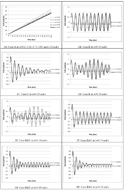
, we solve for Case-B andCase-C to understand the roll behaviour at four frequencies which include smallest to largest frequency, i.e. 0.3, 0.56, 0.74 and 1.2 rad /sec, respectively. The profiles of roll amplitude for Case-A is shown in Fig.3A for various frequencies (
ω
= 0.3, 0.56, 0.74 and 1.2 rad /sec) and the roll amplitude deceases with increase of frequency as obtained from (16). Apart from the frequencyω
= 0.3 rad/sec, other profiles are show linear behavior. For Case-B [Fig. 3B], it can be observed that forω
= 0.3 rad /sec the roll amplitude does not change with variation of speed and manifest sinusoidal behaviour. Case-C shows that for the same frequency minor change in the amplitude is noticed due to the variation of speed with damping, and zero forward shows higher roll amplitude [Fig.3C]. This can be attributed due to the presence of restoring term in roll equation for all groups considered under Case-B and C, and the roll amplitude is maximum for the frequency 0.3 rad/sec. Fig. 3D shows that forω
= 0.56 both the roll amplitudes are same for zero and non-zero forward speed and after time t = 66s, phase shift is noticed when (b44=0). From Case-B and C,6. Conclusions
The objective of the present study is to develop generalized mathematical determination of roll motion and frequency-based analysis in the time domain. The time domain analysis shows the relative importance of the hydrodynamics coefficients through the group based classification. This group-based classification signifies under what conditions which model equations are to be applied. This modeling approach could be useful could be useful to understand the effect of waves on roll motion due to the variation of speed for various frequencies.
REFERENCES
[1] W.E. Cummins, The impulse response function and ship motions, Schiffstechnik, (9):102-109, 1962.
[2] K. W. Holappa, and J. M. Falzarano, Application of extended state space to nonlinear ship rolling, Ocean Engineering, 26, 227, 1988.
[3] N. Salvesen, E. O. Tuck, and O. M. Faltinsen, Ship motions and sea loads, Trans. Society of Naval Architects and Marine Engineering, 78, 250-287, 1970.
[4] L. J. Tick, Differential equations with frequency-dependent coefficients, Journal of Ship Research, 3, 45-46, 1959. [5] W. Frank and N. Salvesen, The frank close-fit ship-motion
computer program, Report 3289, NSRDC, Washington, DC, 1970.
[6] J. H. Vugts, The hydrodynamic coefficients for swaying, heaving and rolling cylinders in a free surface, Report 194, Laboratorium voor Scheepsbouwkunde, Technische Hogeschool Delft, 1968.
[7] S. N. Das and S. K. Das, Mathematical model for coupled roll and yaw motions of a floating body in regular waves under resonant and non-resonant conditions, Appli Math. Modelling, 29, 19-34, DOI: 10.1016 /j.apm. 2004 .0 7.006, 2005.
[8] S. K. Das and S. N. Das, Modelling and analysis of coupled nonlinear oscillations of a floating body in two-degrees of freedom, Acta Mechanica, 181, 1-2, 31-42, DOI: 10.1007/s00707-005-0277-4, 2006
[9] S. K. Das, S. N. Das and P. K. Sahoo, Determination of motion characteristics of a floating body with respect to the variations in degrees of freedom: Analytical study, Ship and Offshore Structures, 3(3), 255-262. DOI: 10.1080/17445300801990939, 2008.
[10] S. N. Das, S. Shiraishi and S. K. Das, Mathematical modelling of sway, roll and yaw motions: order-wise analysis to determine coupled characteristics and numerical simulation for restoring moment’s sensitivity analysis, Acta Mechanica, 213, 305-322, DOI: 10.1007/s00707-009-0278-9 2010
[11] M. Baghfalaki, S. K. Das and S. N. Das, Analytical model to determine response amplitude operator of a floating body for coupled roll and yaw motions and frequency based analysis, Journal of Applied Mechanics, Vol. 4, No. 4. 1-21, 2012. [12] M. Baghfalaki, and S. K. Das, Mathematical Modelling of