International Journal of Emerging Technology and Advanced Engineering
Website: www.ijetae.com (ISSN 2250-2459, Volume 2, Issue 11, November 2012)612
Modeling Of Electrical Response of Illuminated Crystalline
Photovoltaic Modules Using Four- And Five-Parameter
Models
Sakaros Bogning Dongue
1, Donatien Njomo
2, Jean Gaston Tamba
3, Lessly Ebengai
41, 2, 3, 4 Environmental Energy Technologies Laboratory (EETL)/ Faculty of Sciences/ University of Yaoundé 1/ P.O. Box 812
Yaounde/ Cameroon 3
Department of Thermal and Energy Engineering, University Institute of Technology, University of Douala/ PO Box 8698, Douala, Cameroon
Abstract – This paper presents the modeling of electrical response of illuminated crystalline photovoltaic modules using four- and parameter models. The four- and five-parameter models are based on the conventional single-diode equivalent electrical circuit drawn from a light generated current source shunted by a diode and shunt resistance, all in series with series resistance. The simplified four-parameter model neglects shunt resistance assuming it as infinite value and analytically evaluated other parameters; whereas the five-parameter model combined an algebraic simultaneous calculation of the reference parameters with analytical transformation of them for various operating conditions. We succeeded, in this work, to predict with great accuracy the I-V characteristics of mono-crystalline SHELL SP75 and polymono-crystalline GESOLAR GE-P70 photovoltaic modules. The good comparison of our calculated results to experimental data provided by the manufacturers of the modules makes it possible to appreciate the contribution of the shunt resistance and the simultaneous calculation of electrical parameters of photovoltaic modules.
Keywords – Algebraic calculation of parameters, Electrical response, Four- and five-parameter models, I-V and P-V characteristics, Photovoltaic module.
I. INTRODUCTION
Solar energy represents an inexhaustible clean energy source that allows for local energy independence. Photovoltaic (PV) is one of the technologies which make electric power available to anyone virtually anywhere on the planet. Solar energy is indeed the energy that sustains life on Earth for all plants and animals. The miraculous position of the earth’s orbit round the sun gives it the possibility to sustain life and it is essentially a giant solar collector that receives radiant energy from the Sun in the form of electromagnetic radiation [1]. The solar radiation received by a collector lying on the surface of the Earth is a function at the same time of its geographical position, the composition of the atmosphere from the top to the place considered, the orientation of the collector [2] and all shadings such as relief, flora and the human artifices.
Photovoltaic devices illuminated on the surface of the Earth give out an electrical response which depends primarily on the quality, the intensity of the radiation received and the temperature of the illuminated photovoltaic cells. This response consists of the whole electrical parameters and performances of the photovoltaic generator. Since designers select different photovoltaic modules options to obtain the best one before sizing the photovoltaic generator [3] in one hand and a reasonable estimate for the size of a PV system required to supply the energy needed can be made [1] in another hand. Predictions of electrical response of PV devices that led to the determination of the electrical behavior of PV generators in any operating conditions constitute an important element in the processes of the photovoltaic energy exploitation.
The electric behavior of a photovoltaic device under given operating conditions is characterized by its electrical parameters and the current-voltage (I-V) curves describing its operation. Continuous research is performed to improve the accuracy of PV devices, electrical parameters and I-V curves predictions. The overview of different methods commonly used can be gotten from [4 - 6]. These studies are generally based on the calculations of the unknown parameters of the equation of the I-V characteristic and the representation of the I-V curves describing the operation of the device. One can distinguish the analytical methods, which make it possible to calculate independently each parameter according to given limiting conditions [7 - 8], and those based on simultaneous determination of a part or all the set of parameters based on algebraic calculations [9]. Iterative calculations have been carried out recently using artificial intelligence (AI) techniques such as fuzzy logic (FL) [10] and artificial neural network (ANN) [11 – 16].
International Journal of Emerging Technology and Advanced Engineering
Website: www.ijetae.com (ISSN 2250-2459, Volume 2, Issue 11, November 2012)613
The four-parameter model used in this work evaluates individually each parameter of the nonlinear equation of I-V characteristic at STC and any other operating condition from analytical calculations. Whereas the 5-parameter model uses the algebraic resolution to determine the parameters at STC and their calculations in other operating conditions is analytical. The main purpose of this work is to point out the advantages offered by taking into account the shunt resistance and the simultaneous determination of all the parameters based on the algebraic calculations to analytical calculations in the analysis of the electrical response of illuminated crystalline PV modules.
II. PVMODULE MODELS
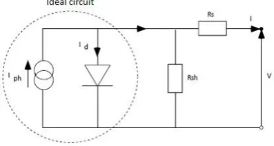
[image:2.595.70.269.579.685.2]An ideal PV device consists to a light generating current source in parallel with one or many diode modeling P-N junction without resistances. Representation with one diode consists of a conventional single-diode model. It is reported that conventional single-diode model cannot adequately reproduces the behavior of PV devices. A modification of this model was proposed by several authors by adding extra diodes [17 – 18] [5].Two-diode model yields more accurate results than single-diode model even though its modifications can be found in literature [19 – 20]. Furthermore, series and shunt electrical resistances are usually included in the aforementioned models to represent internal losses caused by the interconnections of cells to form arrays [21] [4].
In general, multi-diode representations modeling P-N junctions of PV devices offer accurate results at the expense of long computational time. For simplicity, the single-diode model of Fig. 1 is used in this paper. This model offers a good compromise between simplicity and accuracy [3] [21], and has been used by numerous authors.
Fig. 1: equivalent electrical circuit for the one-diode model
An output current equation of I-V characteristic using this model can be written as:
[ (
) ]
, , and are the photo-current, the diode
saturation current, the series resistance and shunt resistance respectively. The modified ideality factor of the junction is given as:
Where is the normal ideality factor, and are the number of cells in series, the Boltzmann constant, the temperature of the cells and elementary charge respectively.
III. FOUR-PARAMETER MODEL
The four-parameter model studied in this work has been used elsewhere [7 – 8]. Assuming as infinite and neglecting it in Equation (1), the four-parameter model is obtained as follows:
( ( ) )
The unknown parameters are denoted at STC as
and ; where the “ref” subscript
refers to the reference operating conditions. The short-circuit current can be found when V=0
The following equations are used to calculate the other parameters at STC [7].
(
)
(
)
Where is the band gap of the material and is the
number of cells in series in the module. The parameters can be found at any other operating conditions by using following equations:
* ( )+
International Journal of Emerging Technology and Advanced Engineering
Website: www.ijetae.com (ISSN 2250-2459, Volume 2, Issue 11, November 2012)614
*
+ *
( )+
IV. FIVE-PARAMETER MODEL
Contrary to the four-parameter model, the shunt resistance is assumed finite in the five-parameter
model. The equation of PV module I-V characteristic at STC is given by:
* (
) +
The five-parameter use here is adjusted from those of [22] [9]. The five parameters are evaluated using correlations for the current and the voltage around key operational points: the short circuit point, the open circuit point and the maximum power point. These correlations give five independent pieces of information resulting to equations (13) through (17)
At short-circuit point:
* (
) +
(13)
At the open circuit point:
* (
) +
(14)
At maximum power point MPP:
* (
) +
At MPP the derivative of the power with respect to the voltage is zero
*
+ (16)
At the short-circuit point, the slope of the I-V curve at short circuit is given by:
(
) (17)
An algebraic method is used for simultaneous resolution of equations (13) - (17) yielding the five reference parameters and then the I-V curve for STC is built using equation (12).
In order to use these parameters for any other operating conditions, it is necessary to obtain expressions for their temperature and irradiance dependence. The parameters: photocurrent , saturation current , ideality factor and series resistance are corrected for new environmental weather using equations (8) to (11) respectively.
The shunt resistance effects have been studied in various operating conditions in [9]. This shows that the shunt resistance appears to change with the absorbed solar radiation for all of the cells, although the effect is most noticeable for cell types that have a relatively small shunt resistance at STC. Equation (18) has been proposed to describe this effect.
( )
V. RESULTS AND DISCUSSION
International Journal of Emerging Technology and Advanced Engineering
Website: www.ijetae.com (ISSN 2250-2459, Volume 2, Issue 11, November 2012)615
Table iThe data of the photovoltaic modules used
Parameters of Modules at STC Shell SP75 GES-P70
Short-circuit current 4,8 A 4,28 A
Open circuit voltage 21,7 V 21,8 V
Maximum power point current 4,4 A 3,98 A
Maximum power point voltage 17 V 17,6 V
Temperature coefficient of 0,002 A/°C 0,0017 A/°C
Temperature coefficient of -0,076 V/°C -0,069 V/°C
Number of cells 36 36
Maximum power 75 W 70 W
Manufacturers usually provide only limited operational data for PV modules. As it can be seen in table (I), data issued including currents and voltages in key operational points are: short-circuit current ( ),
open circuit voltage ( ), current ( ), voltage ( ) at
maximum power point supplemented by the temperature coefficients at open circuit voltage and short circuit current ( and , respectively). These data are
available at STC and sometimes under Nominal Operating Cell Temperature (NOCT) conditions, i.e., irradiance of 800 W/m2, temperature of 45 or 47°C (depending on the manufacturer), ambient temperature of 20°C, wind speed of 1 m/s and AM 1.5 spectrum.
Utilization of available data aforementioned from the sets of equations (4) to (7) and (13) to (17) for the four- and five-parameter models respectively, yields modelled parameters of the I-V characteristic at reference operating conditions for both modules used as it is shown in table (II).
Table ii
Parameters of the modules at stc
Para-meters
Shell SP75 GES-P70
4-Parameter
Model
5-Parameter
Model
4-Parameter
Model
5-Parameter
Model
1,373 1,235 1,287 1,399
4,8 4,85 4,49 4,5
(A) 6,94E-06 1,18E-07 2,98E-07 1,13E-06
0,2747 0,3142 0,2254 0,1648
332,7 333,2
Computed parameters in table (II) are as expected. Except for the infinite value of the shunt resistance for the four-parameter model which is undoubtedly a source of inaccuracy, the values of the parameters calculated using four- or five-parameter models considering STC are consistent with literature [6 – 7] [25 – 26].
[image:4.595.309.554.234.382.2](a) (b)
[image:4.595.60.555.494.705.2]International Journal of Emerging Technology and Advanced Engineering
Website: www.ijetae.com (ISSN 2250-2459, Volume 2, Issue 11, November 2012)616
[image:5.595.53.555.118.335.2](a) (b)
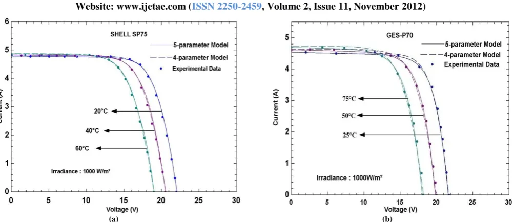
Fig. 3: I-V curves for different temperature levels (a) Shell SP75 (mono-crystalline), (b) GE-P70 (multi-crystalline)
However, the relevance of these values is insufficient, but that of a set of the calculated parameters is relevant. To verify the relevance these set of values, it is necessary to observe the curves resulting from these parameters as shown on figs.
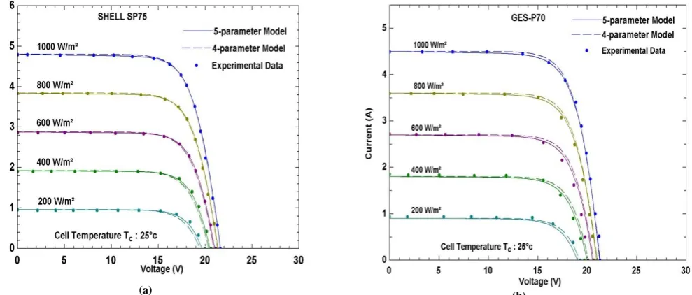
Fig (2) shows the I-V curves for modules Shell SP75 and GES-P70 respectively for different levels of irradiance. It can be seen that, despite the modeling curves do not match experimental data in all points, the five-parameter model strongly agrees to experimental data than the four-parameter model for both types of modules, except for the multi-crystalline module at low irradiance of about 200 W/m² where the four-parameter modeled curve is closer to the experimental data than five-parameter model.
The I-V curves of both modules have been realized by both mathematical models use in this work when subjected to the variation of temperature as it is shown in fig (3). The accuracy of both models was tested for different levels of temperature. All measurements were performed at 1000 W/m².
It can be seen that both models accurately predicted I-V curves of both modules technologies for various temperature levels. However, prediction is better for mono-crystalline than the multi-crystalline technologies.
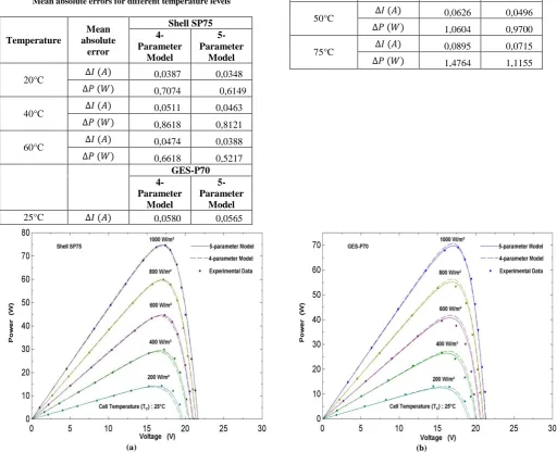
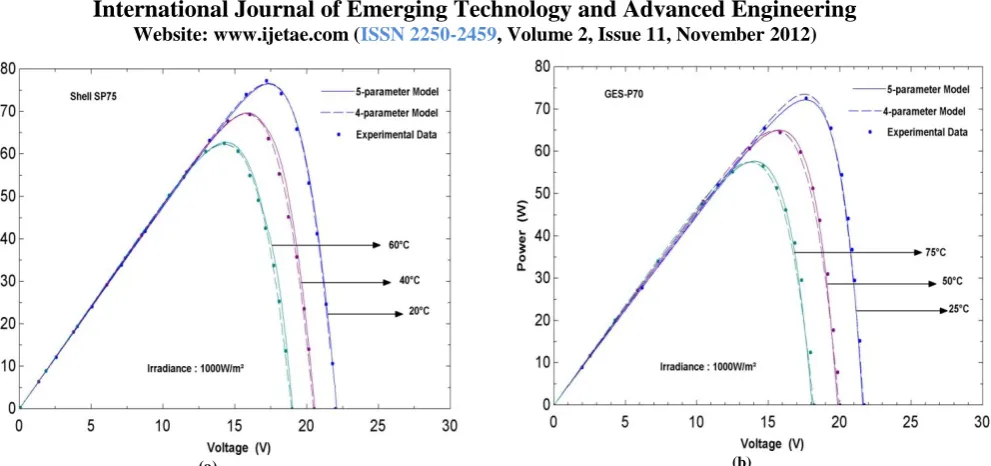
Besides, verifying the accuracy of the PV models to fit the I-V curves of both modules with different levels of solar irradiance and temperature of PV cells, it is important to analyze their capabilities to reproduce power-voltage (P-V) curves of the same PV modules. Figs (4) and (5) show predicted and experimental P-V curves of both modules used in this work for various weather configurations.
As well as it is seen on I-V curves, both models used in this study show that the predicted P-V curves very close to experimental data at STC, and the predicted P-V curves are unfastened to the experimental data when irradiance decreases from 1000 W/m². Whereas, the performances of the models seems to be less affected when subjected to the variation of temperature. The later observation is due to the superposition of the I-V and P-V curves at their horizontal and increasing slopes respectively which could hide inaccuracies especially for multi-crystalline module.
To further investigate the performance of the four- and five-parameter models to reproduce I-V and P-V curves of the analyzed PV modules at various operating conditions, inaccuracies on prediction of these curves are quantified as shown on table (III) and (IV) below.
Table iii:
Mean absolute errors for different irradiation levels
Irrad- iance
Mean abso- lute error
Shell SP75 GES-P70 4-Para-
meter Model
5-Para- meter Model
4-Para- meter Model
5-Para- meter Model
1000 W/m²
0,0323 0,0223 0,0580 0,0565 0,5553 0,4223 1,1100 1,0748
800 W/m²
0,0402 0,0351 0,1117 0,0774 0,7724 0,6652 2,1687 1,5054
600 W/m²
0,0610 0,0238 0,2005 0,1603 1,1549 0,4627 3,7868 2,9797
400 W/m²
0,0781 0,0384 0,1163 0,0808 1,4537 0,7060 1,9330 1,2208
200 W/m²
[image:5.595.305.553.579.780.2]International Journal of Emerging Technology and Advanced Engineering
Website: www.ijetae.com (ISSN 2250-2459, Volume 2, Issue 11, November 2012) [image:6.595.43.556.149.565.2]617
Table ivMean absolute errors for different temperature levels
Temperature
Mean absolute
error
Shell SP75
4-Parameter Model
5-Parameter
Model
20°C 0,0387 0,0348
0,7074 0,6149
40°C 0,0511 0,0463
0,8618 0,8121
60°C 0,0474 0,0388
0,6618 0,5217
GES-P70
4-Parameter Model
5-Parameter
Model
25°C 0,0580 0,0565
1,1100 1,0748
50°C 0,0626 0,0496
1,0604 0,9700
75°C 0,0895 0,0715
1,4764 1,1155
(a) (b)
International Journal of Emerging Technology and Advanced Engineering
Website: www.ijetae.com (ISSN 2250-2459, Volume 2, Issue 11, November 2012)618
[image:7.595.60.556.107.340.2](a) (b)
Fig. 5: P-V curves for different temperature levels (a) Shell SP75 (mono-crystalline), (b) GE-P70 (multi-crystalline)
In any real cell, and , which results in some power losses [27]. The series resistance ( ) represents structural resistances of the photovoltaic panel and the shunt resistance ( ) accounts for current
leakage in the P–N junction [21]. The parasitic resistances affect strongly the slope of the I-V curves; the effects of the series resistances occur at high currents of voltage-source region of the characteristic whereas, the effect of the shunt resistance occurs at small voltage such that the diode current become small compared to the shunt current. Neglecting the shunt resistance results to an overestimated current as it can be notice on figs (2) – (5) where the I-V curves modelled using the four-parameter model are slightly unfastened from those of the five-parameter model and experimental data in current-source region of the characteristics. Moreover, this effect is less remarkable at low irradiance. This can be explained by the increasing shunt resistance at low irradiance [26] [28]. In fact, shunt resistance increase and reaches very significant values at low irradiance, thus four- and five-parameter models curves become very close.
Mean absolute error (MAE) is defined as the mean absolute difference between the experimental and computed current values of the I-V curves for given voltage points. It is carried out for various irradiance and temperature levels for the four- and five-parameter models as shown in table (III) – (IV). For both PV modules used in this work, minor MAE occurs at STC and for the five-parameter model that is undoubtedly ascribable to simultaneous evaluation of parameters that yields the accurate modeling of PV module [6] [21]. In addition, some parameters are kept constant for the four- and five-parameter models when subjected to either irradiance or temperature variations.
It is obvious that the use of constant parameters determined under STC conditions must bring about inaccuracies in others operating conditions [4] [26].
In general, MAEs for the five-parameter model are lesser than those of the four-parameter model for various operating conditions analyzed and for both PV modules studied. The maximum errors occur at the voltage-source region of I-V and P-V curves as it can be notice on figs (2) – (5). It is to be expected because series resistance plays the dominant role in determining the shape of I-V and P-V curves in the voltage-source region and is kept constant for both models. When irradiance and temperature varies, the fixed values of will yield inaccuracies in this region of the I-V and P-V curves [6].
VI. CONCLUSION
The investigation of the performance of both four- and five-parameter models used to predict the electrical response of illuminated mono-crystalline Shell SP75 and multi-crystalline GES-P70 PV modules for various operating conditions is done in this paper. The main conclusions from the analysis of the evaluation of electrical parameters and fitting of the I-V and P-V curves of both modules are:
- plays an important role when PV device operates as current-source generator. It was seen that the four-parameter model that neglects the effects of was inadequate to fit experimental I-V and P-V data in current-source operation. - Most parameters depend on both the cell
International Journal of Emerging Technology and Advanced Engineering
Website: www.ijetae.com (ISSN 2250-2459, Volume 2, Issue 11, November 2012)619
- The main conclusion is that, as was indicated by the MAE values, both the four- and five-parameter models accurately fit experimental data of both PV modules used for various operating conditions analyzed. However, completed five-parameter model with algebraic calculation of parameters yield more accurate current and power predictions than the simplified four-parameter model.
Acknowlegment
The Authors are grateful to Dr. Obounou and Dr. Akana for their efforts in the realization of this work
REFERENCES
[1] Foster, R., Ghassemi, M. and Cota, A. (2010) Solar Energy:
Renewable Energy and the Environment. CRC Press and Taylor & Francis Group.
[2] Kumra, A., Kumar, Gaur M. and Malvi, C. “Sizing of a
standalone photovoltaic system for small scale industry”, International Journal of Emerging Technology and Advanced Engineering 2, n° 8 (2012): 65 - 69.
[3] Carrero, C., Amador, J. and Analtes, S. “A single procedure for
helping PV designers to select silicon PV modules and evaluate the loss resistances”, Renewable Energy 32 (2007): 2579–2589.
[4] Saloux, E., Teyssedou, A. and Sorin M. “Explicit model of
photovoltaic panels to determine voltages and currents at the maximum power point”, Solar Energy 85 (2011): 713–722.
[5] Ishaque, K., Salam, Z., Taheri, H. and Shamsudin, A. “A critical
evaluation of EA computational methods for Photovoltaic cell parameter extraction based on two diode model” Solar Energy 85 (2011): 1768–1779.
[6] Ishaque, K. and Salam, Z. “An improved modeling method to
determine the model parameters of photovoltaic (PV) modules using differential evolution (DE)”, Solar Energy 85 (2011): 2349– 2359.
[7] Celik, A. N. and Acikgoz, N. “Modelling and experimental
verification of the operating current of mono-crystalline photovoltaic modules using four- and five-parameter models”, Applied Energy 84 (2007): 1–15.
[8] Arab, A. H., Chenlo, F., Benghanem, M.,. “Loss- of-load
probability of photovoltaic water pumping systems”, Solar Energy 76 (2004): 713–723.
[9] De Soto, W., Klein, S.A. and Beckman W.A. “Improvement and
validation of a model for photovoltaic array performance”, Solar Energy 80 (2006): 78–88.
[10] Elshatter, T. F., Elhagree, M. E., Aboueldahab and Elkousry A.
A. “Fuzzy modeling and simulation of photovoltaic system” Proceedings of the 14th European Photovoltaic Solar Energy Conference. 1997.
[11] Balzani, M. and Reatti, A. Neural network based model of a PV
array for the optimum performance of PV system. Research in Microelectronics, 2005 Ph.D.
[12] Karatepe, E., Boztepe, M. and Colak, M. “Neural network based
solar cell model” Energy Conversion Management 47 (2006): 1159–1178.
[13] Mellit, A., Benghanem, M., Kalogirou, S. A. “Modeling and
simulation of a standalone photovoltaic system using an adaptive artificial neural network”, Renewable Energy (Elsevier) 32 (2007): 285–313.
[14] Almonacid, F., Rus, C., Hontoria, L., Fuentes, M. and Nofuentes,
G. “Characterization of Si-Crystalline PV module by artificial neural networks”, Renewable Energy 34 (2009): 941–949.
[15] Almonacid, F., Rus, C., Hontoria, L., Munoz, F. J.
“Characterization of PV CIS module by artificial neural networks. A comparative study with other methods”, Renewable Energy 35 (2010): 973–980.
[16] Syafaruddin, E., Karatepe, E. and Hiyama, T. “Development of
real-time simulator based on intelligent techniques for maximum power point controller of PV modules”, The Int. J. Innovative Comput. Inf. Control (IJICIC) 6 (2010): 1623-1642.
[17] Gow, J. A. and Manning, C. D. “Development of a photovoltaic
array model for use in power-electronics simulation studies”, IEE Proceedings – Electric Power Applications 146 , n° 2 (1999): 193–200.
[18] Kassis, A. and Saad M. “Analysis of multi-crystalline silicon
solar cells at low illumination levels using a modified two-diode model”, Solar Energy Materials and Solar Cells 94 (2010): 2108– 2112.
[19] Nishioka, K., Sakitani, N and Uraoka, Y and Fuyuki, T.
“Analysis of multicrystalline silicon solar cells by modified 3-diode equivalent circuit model taking leakage current through periphery into consideration”, Solar Energy Materials & Solar Cells 91 (2007): 1222–1227.
[20] Azab, M. “Improved Circuit Model of Photovoltaic Array”,
International Journal of Electrical and Electronics Engineering 3, n° 11 (2009).
[21] Villalva, M. G., Gazoli, J. R. and Filho, E. R. “Comprehensive
Approach to Modeling and Simulation of Photovoltaic Arrays”, IEEE TRANSACTIONS ON POWER ELECTRONICS 24, n° 5 (2009): 1198 - 1208.
[22] De Soto, W. Improvement and validation of a model for
photovoltaic array performance. MS Thesis, Solar Energy Laboratory, University of Wisconsin, Madison, 2004.
[23] Solar Shell (2002) SP75 Product information Sheet.
www.shell.com/renewables.
[24] GESOLAR. (2010) GES-P70 Polycrystalline Photovoltaic
Module.
[25] Antonio, L., Hegedus, S. (2003) Handbook of Photovoltaic
Science and Engineering. London: John Wiley & Sons Ltd.
[26] Eikelboom, J. A. and Reinders, A. H. M. E. (1997) Determination
of the irradiation dependent efficiency of multicrystalline Si PV modules on basis of IV curve fitting and its influence on the annual performance.» 14-th European PV Solar Energy Conference. Barcelona, Spain, June 30–July 4. 293–296.
[27] Fahrenbruch, A. L. and Bube, R. H. (1983) Fundamentals of
Solar Cells. Academic Press.
[28] Bätzner, D. L., Romeo, A., Zogg H. and Tiwari, A. N.