www.ijsrp.org
Reverse Engineering of Object Oriented System
Abhijeet Gade, Sagar Patil, Shalaka Patil, Divya Pore
Undergrads, Dept. of Computer Engineering, Pune Institute of Computer Technology,
Pune, India
Abstract: In today’s world, every aspect of business is driven by IT. Jobs in IT Industry are never static. They are most dynamic and people keep on switching from one industry to other. So this result in lack of continuity of same people working on same project tills its completion and hence at any time there is need to add new people to the project. So the most important thing for the new comers to any project is to understand the flow of entire project. Reverse engineering is the study of an application's code and behaviour, in order to better understand the system and its design. There are many existing tools that will assist the developer with this undertaking, such as Rational Rose®, jGRASP®, and Eclipse®.So there is necessity to provide a framework which would convert the given code into UML diagrams. So, our project idea is to develop a tool which would convert the given code into UML diagrams. Although, there are certain tools available in the market as given above which do this work, but all these tools are paid application and other which are open source lack behind in certain aspects which would be overcome by our tool.
Index Terms (Ref ACM Keywords):
D.2.2 Design Tools and Techniques- Object-oriented design method
Software Engineering– Design Tools and Techniques- Computer Aided Software Engineering(CASE), Object oriented modelling, Software libraries, Reverse engineering, Modules and Interfaces.
I. INTRODUCTION
n the world of computing applications, approximately 30-35% of the overall total lifecycle costs are devoted to helping the programmer understand the functionality of existing code. This is a necessary task, in order to correctly make required changes in response to new requirements, to resolve errors, or perform other changes [12]. Reverse engineering, analyses a system's code, documentation and behaviour to create system abstractions and design information [13]. Reverse Engineering is, essentially, the practice of examining existing systems, at any stage, to identify elements and dependencies. This information is then used to gain more knowledge about the design, the structure, system code, and functionality. The main objective of our project is to overcome the problem of code tracing. This can be achieved through a project code tracing software, which will give project flow in diagrammatic form by using standard UML notations which results in easy and quick understanding of the flow. Our project will accept the source code files and check if they are compliable. If yes then this files will go through a light weight
parser developed by us. The parser will now extract the information necessary from our point of view to draw the uml diagrams and will store in it proper format in sqlite database. Then the mapping function will convert this information into class diagram and activity diagram.
II. LITERATURESURVEY
A. Multiplicity analysis of association:
Let us outline the approach for the associations:
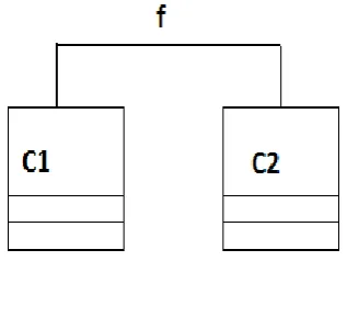
[image:1.595.340.499.382.532.2]1. Prior to the analysis, we have to interpret the notion of UML association and its multiplicity in a precise way:
Fig. 1
An association f as shown in fig. 1 represents a field f in the definition of C1, defined either as C2 f; or as an array, C2 f[ ]; .The C2-end multiplicity of m::n is interpreted as the number of C2 objects f can reference during the lifetime of a C1 object.
2. We then make a key observation, which will be the underlying idea for the multiplicity analysis:
Every assignment to f, f = X, implies a local multiplicity. E.g., the intuition for f = new C2 would be a local multiplicity of 1::1.
3. Local cardinalities depend on where they are encountered. A constructor, called at most once, differs fundamentally from other methods which can be called an arbitrary number of times. Thus, local cardinalities have to be fine tuned" - in our example, f = new C2 would imply a local multiplicity of 0::* if encountered in an ordinary method, since we do not know how often that method might be called.
www.ijsrp.org
4. We store the data regarding association in the database and again show the association relationship in the class diagram where it exists.[14]
B. Reverse Engineering
Related Areas and Sub-Topics in Reverse Engineering
Reverse engineering is a broad subject area, which includes a variety of sub-topics and components. Many terms are used when discussing reverse engineering. Some of these terms include [15]:
• Forward Engineering - the process of starting at the gathering of requirements and then following through to design and finally to the implementation of the application.
• Design Recovery - gathering additional information, like domain knowledge, outside information, and deductive information for inclusion with other observations, to assist the professional in better understanding the system being studied. • Restructuring - the movement from one form to another form at the same level of abstraction without changing the system's output. Essentially, it is changing code to put it in a more structured format.
Reverse Engineering Defined
With society's dependence on the Internet, many businesses need to modify their current applications, to make them web-based and move towards an electronic way of doing business. This trend has created more of an interest in code maintenance and evolution than in the past [15]. Thus, there is now a need for experts in older systems, as software maintenance and evolution is becoming more necessary. Roughly, one third of total life-cycle costs are used for the programmer to understandthe functionality of the existing code [15]. Reverse engineering is the act of recognizing systems elements, along with their corresponding dependencies, to generate a variety of application abstractions and design data from these system elements
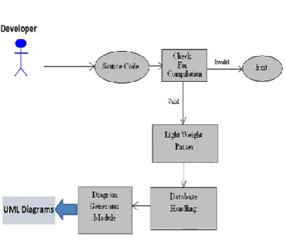
[image:2.595.82.287.549.722.2]III. SYSTEMOVERVIEW
Fig. 2 System Architecture
The system overall consists of four major components. They are stated below in the order in which they will appear in the program structure:
-A Module ―Check for compilation‖ that takes java source file as input and checks whether they are compliable.
-A Module ―Light Weight Parser‖ that will take the valid files as input and extract information necessary for generation of class and activity diagram.
-A Module ―Database Handling‖ that will store the retrieved data in the appropriate format in SQlite database.
-A Module ―Diagram Generator‖ that will draw the class and activity diagram.
IV. DESIGN
Research for this thesis included examining various reverse engineering tools, such as those found in Rational Rose®, Eclipse®, NetBeans®, and jGRASP®, followed by comparing and analyzing the their outputs and methodologies. Our project includes accepting Java programs as input and determining the structural characteristics of the program. Our project includes creation of class diagram and activity diagram (flow diagram and object diagram).
A. Class Diagram
Our main objective while drawing the class diagram is to include the following relationships in the diagram:
1. Generalization 2. Association 3. Dependency
I. Generalization
[image:2.595.342.561.644.736.2]The UML graphical representation of a Generalization is a hollow triangle shape on the superclass end of the line (or tree of lines) that connects it to one or more subtypes. The generalization relationship is also known as the inheritance or "is a" relationship. The superclass (base class) in the generalization relationship is also known as the "parent", superclass, base class, or base type. The subtype in the specialization relationship is also known as the "child", subclass, derived class, derived type, inheriting class, or inheriting type.
www.ijsrp.org
In fig. 3 the classes student and professor are the base classes and the class person is the superclass.
1. An inheritance relationship exists within two classes of a given code when we encounter two keywords in the class definition :
1.Extends 2. Implements
2. So our project includes a parser which consists of such regular expressions which identify these key words in the class definition and retrieves the needed data in our database.
3. Our database consists of following tables that are used to store information needed to draw class diagram. The tables with the column names are given below :
I. Classes(class_id, class_name, static, final, abstract, access, parent)
II. Interface(class_id, interface_id, string)
III. Function(class_id, function_id, type, name, access, static, final, constant)
IV. Parameter(function_id, par_id, type, name)
V. Variable(class_id, var_id, type, name, access, static, final, abstract, const)
VI. Mapping(map_id, s_class, s_func, d_class, d_func)
4. The data from table Classes is used to provide class name and type, the table Variable provide the list and type of variables used within the class and Function provide the functions included in the class.
5. The column parent from table classes and Interface table provide the data required for showing generalisation relationship in the class diagram.
6. Finally, data is interpreteded by drawing a hollow triangle shaped arrow pointing from the base to the superclass.
ALGORITHM:
1. Provide the parser with the source files whose class diagram is to be created.
2. Store the retrieved data in the necessary format in the database.
3. Use the the stored data to draw the class diagram.
II. Association
[image:3.595.309.496.168.203.2]An association represents a family of links. Binary associations (with two ends) are normally represented as a line. An association can be named, and the ends of an association can be adorned with role names, ownership indicators, multiplicity, visibility, and other properties.
Fig. 4 Class diagram example of association between two classes
Our project uses the idea explained in literature survey 3.4 to find out multiplicity in association relation. The parser stores whether a instance variable of any class is defined within a class in the table Variable whose structure is as shown below:
Variable(class_id, var_id, type, name, access, static, final, abstract, const)
III. Dependency
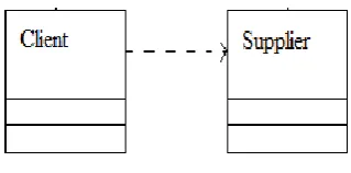
In UML, a dependency relationship is a relationship in which one element, the client, uses or depends on another element, the supplier. We can use dependency relationships in class diagrams, component diagrams, deployment diagrams, and use-case diagrams to indicate that a change to the supplier might require a change to the client.
As the following figure illustrates, a dependency is displayed in the diagram editor as a dashed line with an open arrow that points from the client to the supplier.
Fig. 5 Dependency
The dependency relationship indicates that the client class performs one of the following functions:
1. Temporarily uses a supplier class that has global scope
[image:3.595.337.497.529.608.2]www.ijsrp.org
3. Temporarily uses a supplier class as a local variable for one of its operations
4. Sends a message to a supplier class
A dependency is used when the referenced class is not directly used inside the referencing class, but only passes through the class. For example:
A customerDAO would have a dependency to a customerTO, since the DAO uses to TOto store it in database, but it has no direct association with the TO (the TO is not a instance variable of the DAO).
The difference between dependency and association can be explained by the following example:
Ex:1
public class Flat {
void rent(); }
public class Person {
flat f1; void name();
} Ex:2
public class Flat {
void rent(); }
public class Person {
void name(Flat f1) {
f1.rent(); }
}
Ex:1 shows association whereas ex:2 shows dependency. The difference is that in Ex:1 a instance of class Flat is made in the class Person whereas in Ex:2 an instance is used to call a method of class Flat.
ALGORITHM:
1. Provide the parser with input files.
2. The classes in which only instance variables are created as per ex:1 are stored in table Variable.
3. Whereas the classes in which instances variables are used as per ex:2 are in separate dependency table in the database.
4. With this data retrieved data we can show dependency and association relationship in the class diagram.
B. Activity Diagram
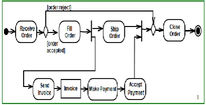
Activity diagrams are graphical representations of workflows of stepwise activities and actions with support for choice, iteration and concurrency. In the Unified Modeling Language, activity diagrams can be used to describe the business and operational step-by-step workflows of components in a system. An activity diagram shows the overall flow of control.
[image:4.595.312.517.198.303.2]Based on data flow models – a graphical representation (with a Directed Graph) of how data move around an information system
Fig. 6 Example of activity diagram
In our approach, the data which is retrieved from the java code and stored in the table Mapping is used to draw the activity diagram. The structure of the mapping table is as shown
Mapping (map_id, s_class, s_func, d_class, d_func )
Consider the following example,
public class Flat {
void rent( ) {
Person P1=new Person(); Apartment A1=new Apartment(); P1.name();
A1.address();
} }
public class Person {
void name( ) {
//Content of function }
} public class Apartment {
void address( ) {
//Content of function }
www.ijsrp.org
So when the above code is traced by the parser the following data is added in the mapping table
Now from this we come to know that from the function rent from class Flat we are calling two functions namely
1. name from class Person 2. address from class Apartment
1. Now our application will first draw the source class Flat.
2. As two functions are been called from class Flat so those two called functions will be displayed in another window when you click on Flat.
3. Now as no other function has been called in name and address the functions would be displayed as action.
V. MATHEMATICALMODEL
Let S be the system that creates class diagram and activity diagram for source code.
S={I,O,F,Sc,Fc | Фs } Where,
I Input O Output F Functions Sc Success case Fc Failure case Фs Set of Rules I = {J,Jg}
J={J1,J2,…….,Jn | Ji {valid java files for desktop applications} }
Jg={T1,T2,...Tn | Ti {Valid java tokens} } n {{method, class, interface} ε Java element }
O={Dm,Dg | Фs }
Dm={Dm1,Dm2,…..,Dmn | Dmi is mapping file} Dg={Dg1,Dg2,……,Dgn | Dgi is actual graphical representation}
Where,
Dgi={U}
U={U1,U2,……,Un } Where,
Uiis UML notation.
F={F1, F2,F3}
F1: checkForCompilation() F1 :ji bi
bi ε B jJ
B={True, False} map_id s_class s_func d_class d_func
www.ijsrp.org
F2: javaPareser() F2 :jiDB jJ
DB= SQLite Database
F3: mapping_to_class_diagram() F3 : (DB) Dgc
DB Database File Dgc Class diagram
F4: mapping_to_act_diagram() F4 : (DB) Dga
DB Database file Dga activity diagram
Initial Condition : I ≠{ф}
SuccessCases: Sc={Sc1∧Sc2∧Sc3∧ Sc4}
Sc1 Class diagram generated correctly Sc2 Sequence diagram generated correctly. Sc3 Successful parsing
Sc4Successful database creation Failure Cases:
Fc={Fc1,Fc2,Fc3, Fc4}, O= ф
Fc1 Input file is not java file
Fc2 Input file is not for java desktop application Fc3 Java code having errors.
Fc4 Unhandled Java cases
VI. FUTURESCOPE
Our future scope is to handle concurrency in activity diagram. Also this project can be used to support various OOP languages other than java.
VII. CONCLUSION
It is clear that our tool provides a clear view of class diagram and activity diagram. Our class diagram also includes dependency relation between various class which is not shown by various other tools. Our approaches analysis various suggested approach and implements a new approach for drawing class diagram and activity diagram.
REFERENCES
[1] Toward the Reverse Engineering of UML Sequence Diagrams for Distributed Java Software,By Lionel C. Briand, Senior Member, IEEE, YvanLabiche, Member, IEEE, and Johanne Leduc
[2] Extending the Sugiyama Algorithm for Drawing UML Class Diagrams: Towards Automatic Layout of Object-Oriented Software Diagrams By: Jochen Seemann
[3] Static Control-Flow Analysis for Reverse Engineering of UML Sequence Diagrams. By: AtanasRountev Ohio State University, Olga Volgin University of Michigan
MiriamReddoch , Hewlett Packard
[4] W. De Pauw, E. Jensen, N. Mitchell, G. Sevitsky, J. Vlissides, and J. Yang, ―Visualizing the Execution of Java Programs,‖ Proc. Software Visualization, pp. 151-162, 2002.
[5] E. Gamma, R. Helm, R. Johnson, and J. Vlissides, Design Patterns—Elements of Reusable Object-Oriented Software. Addison- Wesley, 1995.
[6] IBM:Rational Test Real-Time,
http://www306.ibm.com/software/awdtools/test/realtime/,
www.ijsrp.org
[7] R. Kollmann and M. Gogolla, ―Capturing Dynamic Program Behavior with UML Collaboration Diagrams,‖ Proc. IEEE European Conf. Software Maintenance and Reeng., pp. 58-67, 2001.
[8] R. Kollmann, P. Selonen, E. Stroulia, T. Systa, and A. Zundorf, ―A Study on the Current State of the Art in Tool-Supported UMLBased Static Reverse Engineering,‖ Proc. IEEE Working Conf. Reverse Eng., pp. 22-32, 2002.
[9]Reverse Engineering of UML Specifications from Java Programs. By: Martin Keschenau Chair for Computer Science II Programming Languages and Program Analysis RWTH Aachen University
[10] ―UML 2.0 Superstructure Specification,‖ Final Adopted Specificationptc/03-08-02, Object Management Group, 2003.
[11] ―Reverse Engineering of UML Specifications from Java Programs ‖, Martin Keschenau Chair for Computer Science II Programming Languages and Program Analysis RWTH Aachen University
[12] Tomic, Marijana, "A Possible Approach to Object-Oriented Reengineering of Cobol Programs," ACM SIGSOFT Software Engineering Notes, Volume 19, Issue 2, pp. 1-6, April 1994.
[13] Ali, Muhammad Raza, "Why Teach Reverse