http://dx.doi.org/10.4236/ojce.2016.63030
Investigating Effect of Tunnel Gate
Shapes with Similar Cross Section on
Inserted Forces on Its Coverage and
Soil Surface Settlement
Arash Rostami1, Nima Asghari2, Morteza Askari Ziarati1, Saman Jahani3, Bahman Shahi4
1Department of Civil Engineering, Central Tehran Branch, Islamic Azad University, Tehran, Iran 2Department of Civil Engineering, Noshiravani University of Technology, Babol, Iran
3Department of Civil Engineering, UAE Branch, Islamic Azad University, Dubai, UAE
4Railway Engineering Department, Faculty of Civil Engineering, Isfihan University, Isfihan, Iran
Received 28 December 2015; accepted 24 May 2016; published 27 May 2016
Copyright © 2016 by authors and Scientific Research Publishing Inc.
This work is licensed under the Creative Commons Attribution International License (CC BY).
http://creativecommons.org/licenses/by/4.0/
Abstract
According to technology development and relative facilitation in digging and underground struc-tures, ways, highways, all types of tunnels, underground train network, and other underground settle, storage are number of structure built and developed in advanced countries. In most situa-tion, tunnel digging operations are done years after its construction or are not recorded in new structures regulations; therefore, this research investigates soil settlement and inserting force to tunnel coverage by limiting studies about effects of tunnel shapes on soil settlement using Plaxis, Seismo Signal, and Seismo Aspect. This study shows that rectangular tunnel has the most settle-ment in soil surface and circular tunnel has the least settlesettle-ment but horseshoe tunnel has similar behavior to circular tunnel; however, earth subsidence level by digging this tunnel is more than circular tunnel. In addition, sectional shape has direct effect on inserting forces on tunnel cover-age.
Keywords
1. Introduction
Most buildings have been built based on earthquake standards before building each tunnel beneath it. On the other hand, sometimes reaction effects of structure-soil are considered in designing buildings but effects of tun-nel digging are not considered. Yet, buildings designed and executed before considering tuntun-nel digging with tunnel built under them definitely will be influenced by factors such as earth level movement and consequently structure movement. Another effective and important parameter in soil settlement is tunnel shape. Tunnels are usually built in rectangular, circular, and horseshoe shapes. Studies in this field include works of authors such as Park et al. (2009) [1], Hue et al., (2006) [2], Sanchez et al., (2009) [3] that each one individually evaluates effect of seismic loads of earthquake made on tunnel coverage. In addition, Wang et al., (2012) [4] state that tunnels above settlement have unpenetrated coverage more than tunnels with penetrated coverage. Heydari et al. (2003)
[5] investigate ground level slope, external load, and cross section of tunnel on settlement by tunnel digging us-ing Plaxis software and state that ground level slope doesn’t influence on ground level settlement by tunnel dig-ging. Moreover, section shape change and external load increase ground level settlement. Mohammad Ali Nez-had and Pakbaz (2011) [6] investigate effect of seismic effect on shallow rectangular and circular tunnels and state that seismic effect on rectangular tunnel is more than circular tunnels. Nikzad and Taebi (2011) [7] inves-tigate surficial settlement control originated from tunneling in urbans using injection, congestion, jet, irrigation, and freezing methods and state that injection is the best method of optimizing soil and controlling soil settlement.
Mirhabibi and Sorush (2012) [8] investigate case study of twice tunnel effects in Shiraz by adjacent structures. He investigate tunnel-structure reaction by considering structure, height of tunnel digging, distance of two tun-nels and claim that structure increases vertical settlement. Increase in structure width reduces earth vertical set-tlement level. Azadi et al. (2013) [9] by investigating reaction of tunnel and adjacent structure conclude that in-crease in tunnel distance reduces structure settlement and inin-crease in tunnel digging height inin-creases structure settlement. Musivand and AskariZiyarati (2014) [10] investigate earth level settlement of tunnel digging by in-serting harmonic loads with various frequencies and state that right and left side of settlement curve changes from sloppy to horizontal state by increase in frequency. Rostami et al. (2016) [11] investigate the effect of tun-nel maintenance on surface settlement. Rostami et al. [11] (2016) evaluated the effect of tunnel maintenances on surface and concluded that an umbrella method had significant effect on surface. Rostami et al. [12] (2016) evaluated effect of tunnels with different shapes on ground acceleration and conducted that the rectangular tun-nel have a significant effect on ground responses. Alielahi et al. (2014) studied the use of boundary element method on time-domain for seismic response of buried cylindrical holes in soil. As a result of this research; the numerical results suggested that in a random SV wave with buried hole, horizontal component at the top of the cavity is reduced in comparison with displacement of the empty earth [13]. Also Alielahi et al. [14] (2015) worked on seismic ground amplification by unlined tunnels and concluded that The effect of the tunnel on the seismic ground surface response is gradually decreased or becomes insignificant with increasing the buried depth of the tunnel.
2. Methodology
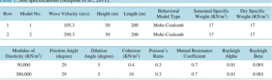
[image:2.595.89.539.589.722.2]In present research, 2 types of soil with recorded specifications in Table 1 have been used so that it can be claimed that soil type (2) is harder than soil type (1). Each soil has a layer and don’t have underground water.
Table 1. Soil specifications (Afifpour et al., 2011).
Row Model No. Wave Velocity (m/s) Height (m) Length (m) Behavioral Model Type
Saturated Specific Weight (KN/m3)
Dry Specific Weight (KN/m3)
1 1 105.3 50 200 Mohr-Coulomb 17 17
2 2 290.3 50 200 Mohr-Coulomb 17 17
Modulus of Elasticity (KN/m2)
Friction Angle (degree)
Dilation Angle (degree)
Cohesion (KN/m2)
Poisson’s Ratio Mutual Resistance Coefficient Rayleigh Alpha Rayleigh Beta
50,000 29 5 0.4 0.3 0.7 0.01 0.001
The mentioned soil is homogeneous and has elastic-perfectly plastic behavior with Mohr-Coulomb criterion and includes of 5 elastic module equations such as internal friction ɸ, dilation angle ψ, CohesionC, soil Poisson’s ra-tio v,behavioral model equations. Shear modulus G can shear wave velocity VS can be calculated based on rela-tions using the mentioned parameters and soil specific weight γ. In addition, interface resistance coefficient has been considered 0.7.
3. Tunnel Specifications
Tunnels have been dug in circular in various height placement, horseshoe, and rectangular forms by similar cross sections and constant height placement were dug in soil and concrete coverage was used for tunnel wall based on Table 2. Tunnel wall was modelled using flexural element which has elastic behavior. In addition, axi-al rigidity (EA) and flexural rigidity (EI) and coverage weight (w) can be obtained by coverage thickness (d) and concrete specific weight (γ).
Soil layer and tunnel were modelled by Plaxis software. In mentioned software, the mentioned soils in Table 1 were modelled then tunnels with different cross sections and height will be dug. Tunnel concrete coverage and structure foundation were also modelled by flexural element and elastic behavior and materials parameters are attributed to them. In order to define interface of elements (such as structure mutual foundation and adjacent soil, etc.), interface element was used. Meshing is the next step in software, then model was dynamically analyzed by inserting side forces as harmonic sine (with different frequencies) and seismic real records. Then needed res-ponses such as seismic acceleration record in soil level will be extracted.
Tunnel Modelling
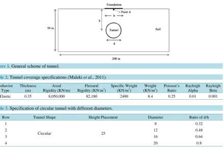
Figure 1 shows the general scheme of model. In the mentioned figure, d is tunnel diameter, h is placement height of tunnel (distance of tunnel enter from ground level) and b is structure foundation width. The dug tun-nels in model is regarding to the following tables. In Table 3, tunnel shape and placement height is constant but tunnel diameter is varied. In this state, the ratio of diameter to height (d/h) will be considered varied. In Table 4, tunnel shape and diameter is constant and height placement is varied, so the ratio of h/d is varied in this table. In
Table 5, tunnel shape is varied and other parameters are constant. The aim to say height placement is distance of tunnel center from ground level.
[image:3.595.101.541.432.727.2]Figure 1. General scheme of tunnel.
Table 2. Tunnel coverage specifications (Maleki et al., 2011).
Behavior Type Thickness (m) Axial Rigidity (KN/m) Flexural
Rigidity (KN/m3) Specific Weight (KN/m3) (KN/mWeight 2) Poisson’s Ratio Rayleigh Alpha Rayleigh Beta
[image:3.595.86.541.652.719.2]Elastic 0.35 8,050,000 82,180 2400 8.4 0.25 0.01 0.001
Table 3. Specification of circular tunnel with different diameters.
Row Tunnel Shape Height Placement Diameter Ratio of d/h
1
Circular 25
8 0.32
2 12 0.48
3 16 0.64
Table 4. Tunnel specifications with different heights.
Row Tunnel Shape Diameter Height Placement Ration of h/d
1
Circular 16
12 0.75
2 18 1.125
3 24 1.5
4 30 1.875
5 36 2.25
6 42 2.625
Table 5. Tunnel specifications with different shapes.
Row Tunnel Shape Diameter (m) Height Placement (m)
1 Circular
16 25
2 Horseshoe
3 Rectangular
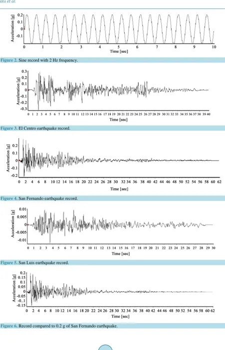
To define boundary conditions, constant and energy absorber boundaries are used. In constant boundary, roll-er support is considroll-ered for vroll-ertical lines, joint support is considroll-ered for horizontal line of soil and horizontal line above soil is without any support. In this way, it has movement in vertical direction and don’t have any movement in horizontal direction. While inserting dynamic loads, waves reflect on model boundaries for turbu-lence. To prevent from intensive reflections, energy absorber boundaries in low part, left, and right sides are used. Analysis software meshes model to 6 or 15 dots triangles that are called meshing. In Plaxis software, av-erage meshing is used. In addition, more sensitive areas meshing such as smaller tunnel walls are considered. Inserted records in this research are harmonic sine and real earthquake accelerograms. Table 6 shows sine record with different frequencies. In the mentioned table, p is record range and its value is 0.2. Moreover, the relationship between rotational frequency (ω) and natural frequency (f) is as following. Record duration of each sine record is 30 second.
Figure 2 shows sine records with 0.2 range and 2 Hz frequency. In addition, real seismic records are shown in
Figures 3-5. These records are all compared to maximum 0.2 gr acceleration in Figures 6-8. =2 f Angular frequency
ω π ω
4. Dynamic Analysis in Model in Plaxis
In this research, analysis time was 30 second with 0.03 second interval. In addition, equations were solved by numerical methods of Newmark design.
5. Discussion and Results
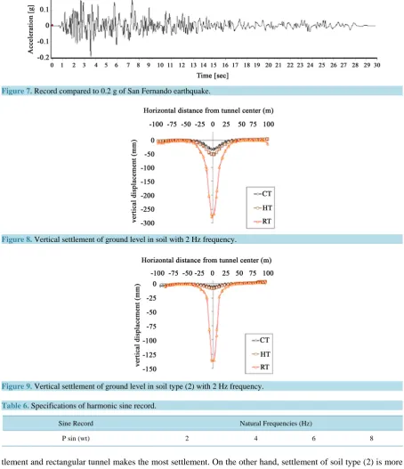
Investigating Vertical Settlement of Ground Level. Vertical settlement of ground level for soil type (1) and (2) are considered under sine records with 2 settlement frequencies under tunnel effects with different crosses (but with similar cross sections). Finally, obtained results in soils (1) and (2) will be compared with each other.
Tunnel cross shape is another variable which effects on soil vertical level settlement will be investigated. In this state, three circular, rectangular, and horseshoe crosses will be used with similar cross sections in constant height. Figure 8 shows cross section in frequency (2). In figures CT, HT, RT indicate tunnel with circular, rec-tangular, and horseshoe sections, respectively. As it is seen from figures, tunnels with rectangular section make more vertical settlement in ground level. Of course, its reason is directly related to tunnel sections. Circular tun-nels make the least settlement.
Figure 2. Sine record with 2 Hz frequency.
Figure 3. El Centro earthquake record.
[image:5.595.92.540.84.171.2]Figure 4. San Fernando earthquake record.
Figure 5. San Luis earthquake record.
[image:5.595.92.535.346.705.2]Figure 7.Record compared to 0.2 g of San Fernando earthquake.
[image:6.595.85.540.92.620.2]Figure 8. Vertical settlement of ground level in soil with 2 Hz frequency.
Figure 9. Vertical settlement of ground level in soil type (2) with 2 Hz frequency.
Table 6. Specifications of harmonic sine record.
Sine Record Natural Frequencies (Hz)
P sin (wt) 2 4 6 8
tlement and rectangular tunnel makes the most settlement. On the other hand, settlement of soil type (2) is more than soil type (1) for being stiffer.
Therefore, sections have direct relation with soil level settlement. On the other hand, soil stiffness reduces movement but in both soil types, rectangular section has the most and circular section has the least settlement.
5.1. Inserted Forces on Tunnel Coverage
5.2. Inserted Forces on Tunnel Coverage with Different Sections under Sine Records with (2) Hz Frequency in Soil Type (1)
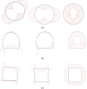
Figures 10 shows general scheme of inserted forces on tunnel walls with circular, rectangular, and horseshoe sections with similar areas in constant height. It is concluded by examining these figures that forces distribution in more homogenous in circular tunnel than other tunnels. In addition, the most shear force and flexural anchor happen for horseshoe tunnel in its low part and for rectangular tunnels on the corners. Inserted forces values on tunnel walls are shown in Table 7 and Table 8. As it is seen in table, inserted forces on tunnel coverage in cir-cular tunnels are less but the most value is made in rectangular tunnels.
(a)
(b)
(c)
Figure 10. (a) General scheme of inserted forces on circular tunnel walls from right side includes axial force, flexural anchor, and shear force; (b) General scheme of inserted forces on horseshoe tunnel walls from right side includes axial force, flexural anchor, and shear force; (c) General scheme of inserted forces on rectangular tunnel walls from right side includes axial force, flexural anchor, and shear force.
Table 7. Inserted forces on tunnel walls with different cross sections in soil type (1) with 2 Hz frequency.
Row Cross Section Axial Force (KN/m) Flexural Anchor (KN/m) Shear Force (KN/m)
1 Circular 1860 80.71 23.5
2 Horseshoe 1460 807.16 855.77
[image:7.595.174.458.203.492.2]3 Rectangular 1860 3440 1760
Table 8. Inserted force on tunnel walls with different cross sections in soil type (1) in (2) Hz.
Row Cross Section Axial Force (KN/m) Flexural Anchor (KN/m) Shear Force (KN/m)
1 Circular 1590 13.51 5.75
2 Horseshoe 1250 412.06 454.24
Inserted forces on tunnel walls with different cross sections under sine records with 2 Hz frequency in soil type (2). Table 8 shows inserted forces on circular, horseshoe, and rectangular tunnel walls in soil type (2) with 2 Hz frequency. As it is seen. Inserted forces on circular tunnels coverage is less than other tunnels for different cross sections but rectangular tunnels make the most force.
5.3. Comparing Inserted Forces on Tunnel Coverage with Different Cross Sections under Sine Record with 2 Hz in Soil Types (1) and (2)
Cross sections have direct effect on inserted forces on tunnel coverage. Examining registered numbers in the mentioned table showed that inserted forces on circular tunnels coverage was less than other tunnels but rectan-gular tunnels made the most force in both soil types. Soil becoming stiff reduces forces. Moreover, it is con-cluded that forces distribution in circular tunnels is more homogeneous than other tunnels. The most value of shear force and flexural anchor happens for horseshoe tunnel in low part and for rectangular tunnel in corners.
5.4. Investigating Vertical Settlement of Ground Level
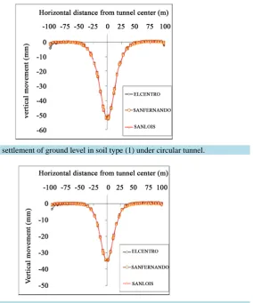
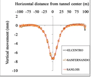
[image:8.595.207.492.370.712.2]Figures 11-13 show vertical settlement of ground level by digging tunnels with different section in oil type (2). As it is indicated, the least ground level settlement was made by digging circular tunnels and the most made by digging rectangular tunnel. Moreover, for homogeneity, the maximum related acceleration to three records was 0.2 g settlement made by them in each relatively similar tunnel. Vertical settlement of ground level was shown in Figures 14-16 by digging tunnels with different sections in soil type (2). As it is seen, the most settlement is made by digging rectangular tunnel and the least settlement is made by circular tunnels. In addition, settlement made by them in each tunnel was relatively similar in both soil types for similarity of maximum related accele-ration to three, 0.2 g records.
Figure 11. Vertical settlement of ground level in soil type (1) under circular tunnel.
[image:8.595.223.401.377.528.2]
Figure 13. Vertical settlement of ground level in soil type (1) under rectangular tunnel.
Figure 14. Vertical settlement of ground level in soil type (21) under circular tunnel.
Figure 15. Vertical settlement of ground level in soil type (2) under horseshoe tunnel.
[image:9.595.237.392.412.541.2] [image:9.595.235.394.572.704.2]5.5. Verification of Modelling
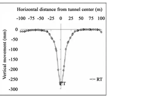
[image:10.595.219.491.163.714.2]In order to verify model, obtained results of sine record with 2 Hz frequency was compared with San Fernando earthquake (with dominant frequency of 1.83 Hz) in soil type (1). It is expected to obtain similar results for nearing of 2 records frequencies. In this part, rectangular and circular tunnels are used based on Table 5. Fig-ures 17-20 show vertical settlement of ground level by digging circular and rectangular tunnels under 2 Hz fre-quency and San Fernando earthquake. As it is observed, results of 2 different records are similar.
[image:10.595.219.488.424.703.2]Figure 17. Vertical settlement of ground level by sine record of 2 Hz.
[image:10.595.223.466.549.705.2]Figure 18. Vertical settlement of ground level by sine record of San Fernando.
Figure 20. Vertical settleme t of ground level by sine record of San Fernando.
6. Conclusion
Digging tunnel in any diameter, placement height and shape make settlement in ground level. As much stiffer soil is, ground vertical settlement is less for soft soil. As much diameter or placement height of tunnel increases, vertical settlement of ground level increases. In tunnels with different cross sections shapes (with similar cross section), rectangular tunnel makes the most settlement in soil level, and circular tunnel makes the least settle-ment, but horseshoe tunnel has similar behavior to circular tunnel; however, ground level settlement made by digging this tunnel is more than what is made by digging circular tunnel and section shape has direct effect on inserted forces loads on tunnel coverage. Investigations show that inserted forces on circular tunnel walls cov-erage are less than others for its cross sections shape but rectangular tunnels insert the most forces and soil stiff-ness reduces forces. Moreover, it is concluded that forces distribution in circular tunnels is steadier than other tunnels. The most shear force and flexural anchor for horseshoe tunnel are in its low part and for rectangular tunnel is on its corners.
References
[1] Peck, R.B. (1969) Deep Excavation and Tunneling in Soft Ground. State-of-the-Art Report. Proceedings of the 7th In-ternational Conference on Soil Mechanics and Foundation Engineering, Mexico, 1969, 225-290.
[2] Huo, H., Bobet, A., Fernandez, G. and Ramirez, J. (1996) Analytical Solution for Deep Rectangular Structures Sub-jected to Far Field Shear Stresses. Tunneling and underground space Technology, 21, 613-625.
http://dx.doi.org/10.1016/j.tust.2005.12.135
[3] Sánchez-Merino, A.L., Fernández-Sáez, J. and Navarro. C. (2009) Simplified Longitudinal Seismic Response of Tun-nel Lining to Surface Wave. Soil Dynamics and Earthquake Engineering, 29, 579-582.
http://dx.doi.org/10.1016/j.soildyn.2008.06.003
[4] Sun, C. and Wang, Q. (2012) Effects of Underground Structure on Acceleration Response of Site. Advanced Materials Research, 368-373, 2791-2794.
[5] Heydari, M.R., et al. (2003) Effect of Ground Slope, External Load, and Tunnel Cross-Sectional Shape of Earth Sub-sidence by Digging Soil Tunnels. 6th Conference of the Tunnel, College Civil, Iran Industry and Science University, Tehran, 27-29 January 2004.
[6] Mohamamd, A., Pakbaz, R. and Sirus, M. (2011) Seismic Effect on Shallow Rectangular Tunnels. The 6th National Conference of Civil Engineering, 26-27 April 2011, Semnan University, Semnan.
[7] Mahdi, N. and Vahid, T. (2011) Controlling Surficial Settlement in Tunneling in Urban Area Using Improvement of Earth Specification. 1st National Conference of Zibakenar Civil and Development, Zibakenar, March 2014.
[8] Mirhabibi, A. and Soroush, A. (2012) Effects of Surface Buildings on Twin Tunnelling-Induced Ground Settlements.
Tunnelling and Underground Space Technology, 29, 40-51. http://dx.doi.org/10.1016/j.tust.2011.12.009
[9] Azadi, M., Pourakbar, S. and Kashfi, A. (2013) Assessment of Optimum Settlement of Structure Adjacent Urban Tun-nel by Using Neural Network Methods. Tunnelling and Underground Space Technology, 37, 1-9.
[10] Mohsen, M. and Meysam, B. (2013) Investigating Effect of Earth Sloppy Effect on Ground Level Settlement by Dig-ging Tunnel. 1th National Conference on Engineering and Technology, Aredil, 20 May-23 October 2013.
[11] Rostami, A., Kamali-Dehkordi, P., Askari-Ziarati, M., Jahani, S. and Lotfi, K. (2016) The Types of Tunnel Mainten-ance in Umbrella Arch Method. Open Journal of Civil Engineering, 6, 156-162.
http://dx.doi.org/10.4236/ojce.2016.62014
[12] Rostami, A., Askari-Ziarati, M., Shahi, B. and Jahani, S. (2016) Evaluation of Seismic Behavior and Earth’s Surface Acceleration, by Interaction of Tunnels with Different Shapes and Different Types of Soils. Open Journal of Civil En-gineering, 6, 242-253. http://dx.doi.org/10.4236/ojce.2016.62022
[13] Hamid, A. (2012) Applying a Time-Domain Boundary Element Method for Study of Seismic Ground Response in the Vicinity of Embedded Cylindrical Cavity. International Journal of Civil Engineering, 11.