A FUZZY APPROACH FOR REPRESENTATIVE NODE
SELECTION IN CROSS LAYER TCP
1A. CHANDRASEKAR, 2 Dr. S. ARUMUGAM 1
S.N.S College of Technology, Department of Computer Science and Engineering, Coimbatore, INDIA 2
Principal, Nandha Engineering College, Erode, INDIA
E-mail: [email protected]
ABSTRACT
A cross-layer based improved Transmission Control Protocol (TCP) protocol ensuring fair throughput and reliability was proposed in the previous investigations. In this protocol, data path was segmented, and representative nodes are maintained in every segment for any TCP connection. A Transmission Controller Module (TCM) is used by the representative node to determine bandwidth and delay in transmission and a Local Acknowledgement (LACK) message is sent to the source. Each LACK’s reception source calculates congestion window’s desired size, based on the forward path bandwidth, and Round Trip Time (RTT) values on forward path thereby avoiding congestion for larger extents, and increasing network data transmission rate. This study proposes to extend TCP. Representative nodes use fuzzy logic concept, dynamically. A node becomes a representative node when its two hop neighbours have poor link quality, high mobility and reduced bandwidth. The fuzzy rule generated in this study ensures increased throughput and reduced delay compared to conventional TCP.
Keywords: Transmission Control Protocol (TCP), Local Acknowledgement (LACK) message, Fuzzy Logic,
Fuzzy Rule
1. INTRODUCTION
Mobile Ad-Hoc Networks (MANETs) are dynamic networks without fixed infrastructure because of their wireless nature, deployed as multi-hop packet networks. It has dynamic topology due to node mobility [1]. MANETs are known for self-organizing capabilities, and rapid deployment ensuring that MANETs are used for rescue forces in emergencies [2]. MANETs are a collection of many mobile nodes forming temporary networks without any central access point. MANET’s characteristics like dynamic topology, node mobility, ensure more freedom and self-organizing capability differentiating it from other networks. MANET applications are diverse and range from large, mobile, dynamic networks, to small, static networks constrained by power sources. In addition to legacy applications that change from traditional infrastructure environment to an ad hoc context, many new services can and are generated for new environments. It includes military battlefield, sensor networks, commercial sector, medical service, personal area network [3].
Transmission Control Protocol (TCP) is a transport protocol guaranteeing reliable data packets over wired networks. Tough tuned for wired networks, TCP performance is wanting in MANETs because TCP's assumption of congestion being responsible for packet loss is invalid in MANETs where wireless channel errors, link contention, mobility and multipath routing can corrupt packet delivery. When TCP misinterprets losses as congestion invoking congestion control procedures, it results in performance degradation and unfairness [4].
1. Slow-start
2. Congestion avoidance
3. Fast Retransmit.
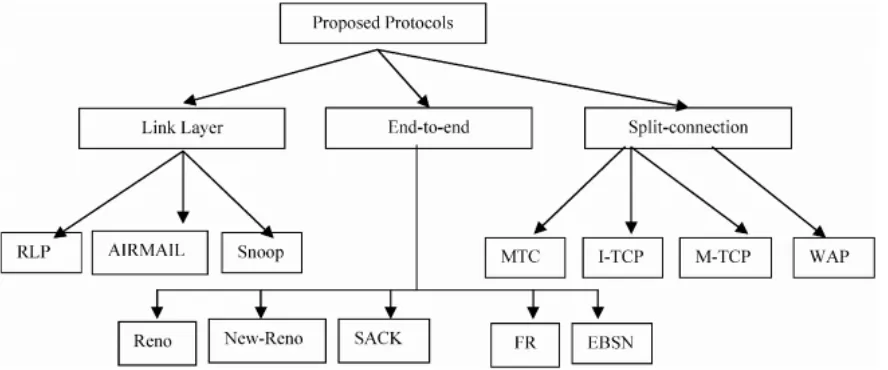
Regular TCP was not designed for mobile hosts and so regular TCP cannot be expected to perform well in mobile networks. Figure 1 shows the
[image:2.595.90.534.248.433.2]taxonomy of Protocols to improve the performance of TCP on mobile networks. A reason for this is that wired links have low Bit Error Rates (BER), in contrast to wireless links which suffer from high bit error rates [5].
Figure 1: Protocols to improve the performance of TCP on mobile networks.
The TCP protocol was extensively tuned for good performance at the transport layer in conventional wired networks. However, TCP in its present form does not suit MANETs where broken routes related packet loss results in the counterproductive call of TCP’s congestion control mechanisms. Though many studies are conducted and protocol modifications suggested, improving TCP performance in MANETs is still under study. Performance studies have focused either on specific protocols or are restricted to single TCP connection [6].
Link Quality algorithms are classified through various criteria, one being the type of input that the algorithm’s use for prediction. Inputs can be
location measurements, signal-power
measurements or other measurements like the ratio of transmitted to received packets in a time interval. Input type is an important criterion by which to classify LQP algorithms as it represents algorithms
focus. Signal-power measurements based
predictions focus on radio propagation model while
predictions based on location measurements focus on mobility model. Another criterion which classifies existing algorithms is LQP output. If the output is a finite set of states subset, the prediction is classified as deterministic. Usually, deterministic prediction algorithms have two possible output states; packets are predicted as either lost or received for some time in the future. If LQP algorithm output is an infinite set of states subset, the prediction is classified as stochastic as output is such cases is usually a probability. Another
classification criterion is LQP application.
Successful applications are found in routing, multicast communication, group communication and clustering. A final classification criterion is radio propagation model based on LQP algorithm. As link quality is dependent on radio propagation
model, algorithms focusing on location
measurements and mobility models are
In this research, the extension of TCP is proposed. The representative nodes are dynamically selected using fuzzy logic concept. A node can become representative node if its two hop neighbours have poor link quality, low bandwidth and high mobility. The rest of the paper includes literature survey of related works, materials and methods used and results.
2. RELATED WORKS
A cross-layer design for TCP throughput optimization in cooperative relaying networks was proposed by Wei, et al., [8]. The authors investigated TCP throughput in cooperative relaying networks and resorted to a cross layer design approach when selecting a relay for TCP
throughput optimization. Compared to the
suggested scheme under different physical layer and link-layer parameter simulations it was revealed that TCP throughput improved greatly through the use of optimal relay selection scheme.
TCP congestion control using fuzzy regulation approach was proposed by Lian, et al., [9] which included a Takagi-Sugeno (T-S) fuzzy controller for Active Queue Management (AQM) with Explicit Congestion Notification (ECN) for improving Internet communications performance. Compared to other AQM schemes, experiments showed that suggested AQM had improved performance regarding packet loss, throughput and queue length fluctuation.
A fuzzy logic congestion control in TCP-IP differentiated service networks for quality of
service provisioning was proposed by
Chrysostomou, et al., [10]. A brand new AQM scheme ensuring congestion control in TCP-IP networks using a fuzzy logic control approach was presented. The fuzzy control method offered major improvements to control congestion in TCP-IP Diff-Server networks providing quality of service.
A delay-based approach using fuzzy logic for improving TCP error detection in ad hoc networks was proposed by Oliveira and Braun [11].The authors investigated fuzzy logic theory to assist TCP error detection mechanism in networks. An elementary fuzzy logic engine was an intelligent technique to discriminate packet loss caused by congestion due to wireless induced errors packet loss.
An energy efficient cross-layer routing protocol in WSN based on fuzzy logic was proposed by Jaradat, et al., [12] which suggested an energy aware routing scheme based on a cross-layer
approach for WSNs aimed at minimizing overall consumed energy and thereby increasing network
life. The proposed cross-layer algorithm’s
performance was evaluated using discrete event simulation
A new cross layer TCP pacing protocol for multi-hop wireless networks was proposed by Xie [13]. The authors proposed a cross layer TCP pacing protocol through control of contention window’s lower bound for optimization of overall
TCP throughput on multi-hop topology.
Comparison of simulations was done to verify the proposed protocol’s improvement.
The impact of hidden node collisions on multi-hop TCP flows performance was focused on by Valletta, et al., [14] which traced the issue of collisions between RTS frames from starved flow and long data frames from active flow. Such collisions result in rapid MAC contention window increase at TCP sender of starved flow; this along with TCP’s congestion control algorithm allows running flow to hold channel for long till the situation is reversed. They revealed that a multi-channel MAC can ease flows competition.
A Div-TCP solution running ordinary TCP algorithm with two extra operations regarding the handoff process was proposed by Assaf [15]. The operations are triggered by Div-TCP when the handoff is anticipated. Retransmission Time Out (RTO) is concerned with ensuring a suitable RTO at every node in end-to-end connection to prevent triggering congestion algorithms where Buffer Division (BufDiv) maintains sender’s throughput by creating a TCP connection before the occurrence of handoff.
A cross layer approach enhancing TCP performance over wireless networks was proposed by Priya and Murugan [16]. A new cross-layer approach (Link Layer CLAMP) which avoided TCP Acknowledgement (ACK) packet transmission over a wireless channel was proposed, saving time which can be used by nodes for data packet delivery.
A cross-layer mechanism for TCP connection over wireless uplink in cellular networks was proposed by Yu and Yin [18]. It controlled the retransmission timer startup in TCP layer at MH according to information from radio link control (RLC) layer, enabling TCP protocol to operate over uplink without suffering packet losses due to fading channel and mobility. Additionally, implementation
of the proposed mechanism only needed
modifications of MH protocol stack.
The problem of transport layer protocols performance degradation due to of wireless local area networks congestion was presented by Kliazovich and Granelli [19]. After analysis of available solutions, a cross-layer congestion avoidance scheme (C3TCP) capable of higher performance by gathering capacity information like bandwidth and at the link layer delay was presented.
3. METHODOLOGY
This work proposed to improve LACK protocol by proposing QOS parameter estimation and selection of representative node using fuzzy logic. Detailed discussion of each technique is discussed.
3.1 Overview
Delay and bandwidth estimation is performed at destination and transmitted to the source to reveal successful data reception. When node number which is to traverse network increases it leads to increased network delay caused by the fact that path length to be traversed is proportional to delay in
data transmission. Hence, acknowledgement
message reception at source consumes much time and increases network delay problem resulting in network congestion.
This research develops an improved TCP protocol to offset the above problems. The data transmission path is split into segments initially in this protocol. A representative node is maintained for bandwidth and delay calculation for every segment. On receipt of data packet, the
representative node generates a Local
Acknowledgement (LACK) message and forwards it to source with calculated bandwidth and delay value. The representative node transfers it to next representative node in the destination path. The source on receipt of LACK message determines bandwidth and delay value and estimates congestion window accordingly. Thus, in this protocol, Delay and bandwidth involved in data
transmission are estimated faster thereby
maximizing network efficiency.
3.2 Bandwidth and Delay Estimation 3.2.1 Bandwidth estimation
Bandwidth B available for transmission of certain data is got by knowing the size of data D and time T taken for transmission of data over specific link.
Bandwidth is calculated by
B D
T
= (1)
where
T
=
T
in−
T
out+
T
tr(2)
T is the time required for transmission of a single data packet using CSMA/CA.
Tin-Tout includes data queuing delay that
corresponds to time a node was waiting for all nodes to finalize pending transmissions and also channel to channel access delay using random back off and optional RTS/CTS exchange.
Ttr is the time required for data frame
transmission and corresponding acknowledgement.
It is necessary to consider the framework used by the physical layer. According to physical and link layer specifications, time required for data packet delivery (including data frame and corresponding ACK) is calculated as follows:
tr data ack
T
=
T
+
SIFS
+
T
+
DIFS
(3). . . . . data
PLCP preamble PLCP header
T
Basic rate
MAC header FCS Data
Data Rate Data Rate
+ = + + (4)
.
.
.
.
ackPLCP preamble
PLCP header
T
Basic rate
ACK header
FCS
Data Rate
+
=
+
+
(5)The bandwidth measurement algorithm is the following:
1. Store timestamp Tin for data arrived at the link
layer for further transmission. Data can arrive from other nodes for forwarding or it can be generated by upper layers of the protocol locally.
2. Prior data frame transmission, at time Tout
queuing and packet transmission time Ttr using Equation (3).
3. Calculate bandwidth experienced by packet using Equation (1).
3.2.2 Delay estimation
In proposed delay estimation technique forward and backward delays are differentiated. Forward delay has data pipe length between the sender and receiver nodes while backward delay measures time needed for TCP ACK packets delivery.
1. Forward delay: A data burst’s single-hop forward delay includes channel access delay; time needed for data delivery to the physical layer including related physical and link layer overhead. It excludes link layer queuing delay.
Forward delay is calculated using Equation (2) setting Tin to be equal to time packet leaves queue preparing for actual transmission on link layer. Such estimation avoids insertion of link layer
queuing delay to the Tin - Tout component.
forward tr
D
=
T
(6)
2. Backward delay. TCP reliability is achieved by implementing a positive acknowledgement scheme. The receiver acknowledges successful data delivery with TCP ACK packets going back to sender.
Contrary to forward delay measurement
technique described, TCP ACK delay includes transmission and queuing delays, i.e. equal to the difference between time TCP ACK packet was generated by receiver node and reception by TCP sender. Single link backward path delay is calculated using Equation (2).
–
backward in out tr
D
=
T
T
+
T
(7)
Total delay
D
D
forwardD
backward+
=
(8)
3.3 Link Quality
The link quality is estimated on the basis of Expected Transmission Count (ETX) [20] in this study. The route with least expected number of transmission is found using ETX metric. It finds routes with high throughput regardless of loss in packets [20]. The predicted number of transmission required to send a packet through a link gives the ETX of a link and sum of link ETX in a route gives the route ETX. The ETX of a link is computed
based on forward delivery ratio, df, and reverse
delivery ratio, dr, of the link. The probability of a
packet arriving successfully to the destination is df
and the probability of the ACK packet successful
received is dr and df×dr gives the expected
probability of a transmission that is successfully received and acknowledged. Retransmission from a sender occurs only when packet is not successfully
acknowledged. The expected number of
transmissions is:
1
*
f rETX
d
d
=
(9)3.4 Protocol Functionalities
1] The path involved in TCP data packet transmission from source S to destination D is divided into segments with each segment having a node called as representative node R being maintained for delay estimation and bandwidth.
2] The path is divided into predetermined hop count based segments.
3] Representative node selection is based on maximum bandwidth capability i.e., node within predetermined hop count supporting maximum bandwidth and reduced delay is chosen as representative node.
4] A Transmission Controller Module (TCM) is inserted in each representative node below transport layer to avoid changes at protocol stack’s transport layer.
5] When data packet is transmitted from source S to first representative node R1, TCM asks for bandwidth required and transmission if any from the link layer. This is delivered with TCP data packet.
6] R1 sends a LACK message with MAC header to source.
7] TCM traces outgoing LACKs having access to TCP data packet headers. If produced LACK acknowledges received TCP data packet, TCM forwards request to link layer to include stored bandwidth–delay information into MAC-layer header of outgoing TCP data packet.
separation encapsulated in the frame from MAC header.
9] At source’s side, TCM requests end-to-end measurements from link layer on receipt of LACK message and then calculates the congestion window’s desired size based on the forward path’s bandwidth and RTT values.
10] Source S transfers next data packet to the destination.
11] Meanwhile representative node R1 forwards data packet to destination through remaining intermediate and representative nodes.
12] Representative node R2, on receipt of data packet calculates delay and bandwidth involved and sends LACK message to R1.
13] R1 on receipt of LACK message calculates congestion window based on bandwidth and delay values delivered.
14] Representative node R1 forwards next data packet to representative node R2.
15] Data packets are also transferred through
intermediate and representative nodes till
destination is reached.
16] On receipt of data packet at destination, an end to end acknowledgement (ACK) message is generated along with LACK message at destination D. LACK message is forwarded to previous
representative node and ACK message to the source.
Transport layer functionalities are divided into congestion control and end-to-end reliability. Correspondingly, the transmission window at source is also split into congestion window and end-to-end window. The congestion window is always a sub-window to the end-to-end window. While congestion window changes with rate of arrival of LACKs from next proxy, end-to-end window changes with rate of arrival of end-to-end ACKs from destination.
3.5 Protocol Architecture & Flowchart
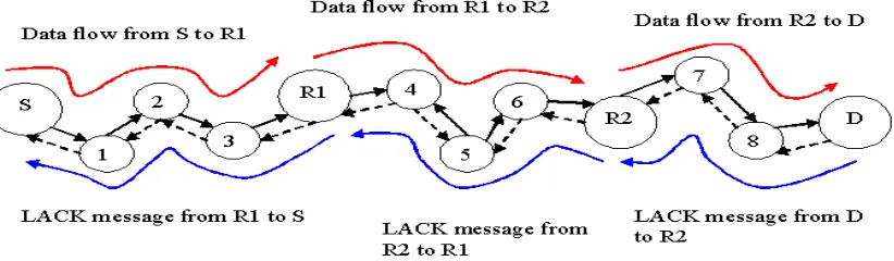
[image:6.595.103.514.496.616.2]Data packet transmission from source to destination is shown in figure 2. It is assumed that predetermined hop count is four. Representative nodes are R1 and R2. On receipt of data packet at representative node R1, a LACK message is generated and forwarded to source by R1 includes estimated bandwidth and delay value. R1 forwards data packet to R2. On receipt of LACK message at source, it transmits next data packet to R1. When R2 receives data packet, it transmits LACK message to R1 and forwards data packet to the destination node, D. The latter on receipt of data packet, generates LACK and end to end acknowledgment message, ACK. Destination node, D forwards LACK message to R2 and ACK message to the source.
The suggested protocol has following advantages:
•It handles congestion control and end to end
reliability separately reducing control
overhead.
•It uses cross-layer interactions with MAC
•It adapts to changes in topology.
•It ensures improved throughput for contesting
flows.
3.6 Fuzzy Logic Control
The fuzzy logic control model includes fuzzy rules, fuzzifier, fuzzy inference engine, and defuzzifier. The common fuzzy inference technique called Mamdani Method [21] is used as it is simple. The process has four steps:
•Fuzzification of input variables energy,
concentration and centrality - taking crisp inputs from these and determining the degree to which inputs belong to appropriate fuzzy sets.
•Rule evaluation - taking the fuzzified inputs
and applying them to fuzzy rule antecedents. It is applied to consequent membership function (Table 1).
•Aggregation of rule outputs - process of
unification of rules outputs.
•Defuzzification - input for defuzzification
process is aggregate output fuzzy set chance and output is one crisp number.
During defuzzification, it locates the point where a vertical line slices aggregate set chance into two equal masses. The Centre of Gravity (COG) is calculated over points sample on aggregate output membership function using the following formula:
( )
( )
(
* /)
A A
COG=
∑
µ x x∑
µ x (10)where, is membership function of set A.
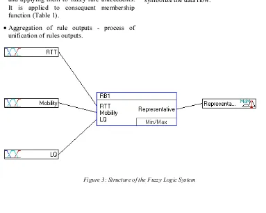
The system structure identifies the fuzzy logic inference flow from the input variables to the output variables. The fuzzification in the input interfaces translates analog inputs into fuzzy values. The fuzzy inference takes place in rule blocks which contain the linguistic control rules. The output of these rule blocks is linguistic variables. The defuzzification in the output interfaces translates them into analog variables.
[image:7.595.97.480.419.725.2]The following figure 3 shows the whole structure of this fuzzy system including input interfaces, rule blocks and output interfaces. The connecting lines symbolize the data flow.
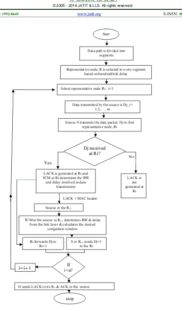
Figure 4:Flowchart of Proposed Method
S or Ri-1 sends Dj+1 to the Ri Ri forwards Dj to
Ri+1
i=i+1
i<n? IfD sends LACK to its Ri-1& ACK to the source
stop
Data path is divided into segments
Representative node, R is selected in every segment based on bandwidth & delay
Source S transmits the data packet, Dj to first representative node, Ri
Dj received at Ri?
Yes
No
LACK is generated at Ri and TCM at Ri determines the BW
and delay involved in data transmission
LACK is not generated at
Ri Select representative node Ri , i=1
Data transmitted by the source is Dj; j= 1,2,…., m
Start
Source or the Ri-1
LACK + MAC header
TCM at the source or Ri-1 determines BW & delay from the link layer & calculates the desired
Variables Inputs
Table 1: Variables of Group "Inputs"
# Variable Name Type Unit Min Max Default Term Names
1 LQ Units 0 1 0.5 low
medium high
2 Mobility Units 0 1 0.5 decrease
steady increase
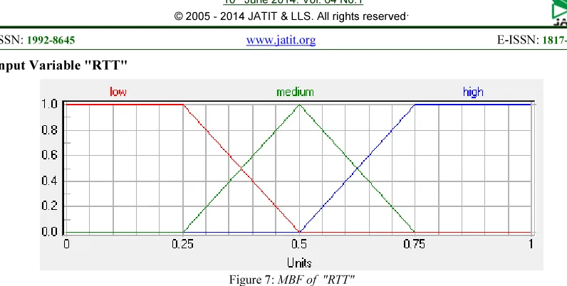
3 RTT Units 0 1 0.5 low
medium high
Outputs
Table 2: Variables of Group "Outputs"
# Variable Name Type Unit Min Max Default Term Names
4 Representative Units 0 1 0.5 negative
zero positive
Input Variable "LQ"
Table 3: Definition Points of MBF "LQ"
Term Name Shape/Par. Definition Points (x, y)
low linear (0, 1) (0.25, 1) (0.5, 0)
(1, 0)
medium linear (0, 0) (0.25, 0) (0.5, 1)
(0.75, 0) (1, 0)
high linear (0, 0) (0.5, 0) (0.75, 1)
(1, 1)
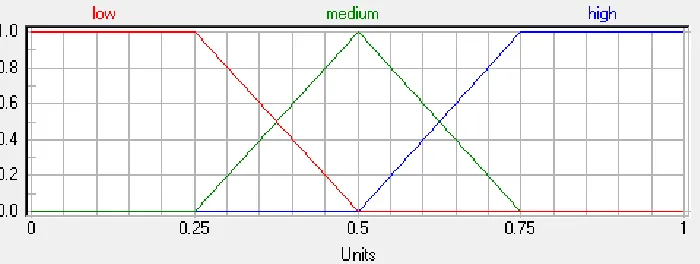
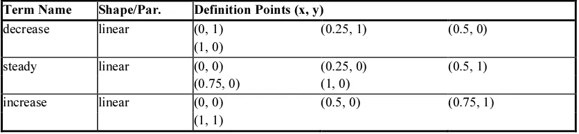
[image:10.595.121.478.327.461.2]Input Variable "Mobility"
Figure 6: MBF of "Mobility"
Table 4: Definition Points of MBF "Mobility"
Term Name Shape/Par. Definition Points (x, y)
decrease linear (0, 1) (0.25, 1) (0.5, 0)
(1, 0)
steady linear (0, 0) (0.25, 0) (0.5, 1)
(0.75, 0) (1, 0)
increase linear (0, 0) (0.5, 0) (0.75, 1)
[image:10.595.100.518.522.619.2]Input Variable "RTT"
[image:11.595.97.518.326.422.2]Figure 7: MBF of "RTT" Table 5: Definition Points of MBF "RTT"
Term Name Shape/Par. Definition Points (x, y)
low linear (0, 1) (0.25, 1) (0.5, 0)
(1, 0)
medium linear (0, 0) (0.25, 0) (0.5, 1)
(0.75, 0) (1, 0)
high linear (0, 0) (0.5, 0) (0.75, 1)
(1, 1)
Output Variable "Representative"
Figure 8: MBF of "Representative"
Table 6: Definition Points of MBF "Representative"
Term Name Shape/Par. Definition Points (x, y)
negative linear (0, 0) (0.25, 1) (0.5, 0)
(1, 0)
zero linear (0, 0) (0.25, 0) (0.5, 1)
(0.75, 0) (1, 0)
positive linear (0, 0) (0.5, 0) (0.75, 1)
[image:11.595.120.479.462.599.2] [image:11.595.100.517.637.734.2]Rule Blocks Parameter
Aggregation: MINMAX
Parameter: 0.00
Result Aggregation: MAX
Number of Inputs: 3
[image:12.595.111.488.253.463.2]Number of Outputs: 1
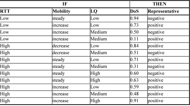
Table 7: Rules of the Rule Block "RB1"
IF THEN
RTT Mobility LQ DoS Representative
Low steady Low 0.94 negative
Low increase Low 0.73 positive
Low increase Medium 0.50 negative
Low increase Medium 0.11 positive
High decrease Low 0.84 positive
High decrease Medium 0.51 negative
High steady Low 0.71 positive
High steady Medium 0.31 negative
High steady High 0.60 negative
High steady High 0.63 positive
High increase Low 0.59 positive
High increase Medium 0.48 positive
High increase High 0.91 positive
4. RESULTS AND DISCUSSION
In this study, the extension of TCP is proposed. The representative nodes are dynamically selected using fuzzy logic concept. A node can become representative node if its two hop neighbours have poor link quality, low bandwidth and high mobility. The fuzzy rule generated in this research provide increased throughput with reduced delay, when compared with traditional TCP.
Figure 9: Average Data Dropped
From figure 9, it is shown that proposed fuzzy cross layer TCP provide low average data drop compared to TCP.
[image:12.595.92.524.550.729.2]
Figure 10: Average Retransmission Attempt
Figure 11: Throughput in bits/seconds
From the figure 11, it is obtained that the proposed fuzzy Cross Layer TCP throughput
increases at 11.1 % from TCP and 2.3% from CLTCP respectively 0 0.0002 0.0004 0.0006 0.0008 0.001 0.0012 0.0014 0.0016 0.0018 0.002 4 8 8 4 1 2 0 1 5 6 1 9 2 2 2 8 2 6 4 3 0 0 3 3 6 3 7 2 4 0 8 4 4 4 4 8 0 5 1 6 5 5 2 5 8 8 E n d t o E n d d e la y i n s e c o n d s
stimulation time in seconds
TCP
CLTCP
Fuzzy CLTCP
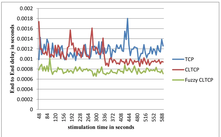
Figure 12: End to End delay in seconds
From the figure 12 it is obtained that the proposed fuzzy Cross Layer TCP End to End Delay decreases at 34.24 % from TCP and 27.94% from CLTCP respectively.
5. CONCLUSION
[image:13.595.99.474.425.658.2]fair throughput and reliability. The path selected for data packet transmission in this technique is divided into segments based on a predetermined hop count. In each segment, a representative node calculates bandwidth and delay involved. A congestion window is estimated from LACK message transmitted by representative nodes to the source or previous representative node on receipt of data packets. On receipt of LACK message, source sends next data packet. Data packets are thus transmitted to destination through representative nodes. On receipt of data packets at the destination, it generates LACK message with normal ACK message to be transmitted to source assuring end to end reliability. Hence this technique ensures congestion control with reliability and improved throughput. Simulation results revealed that the suggested protocol achieves, increased throughput with reduced delay when compared to conventional TCP and CLTCP.
REFRENCES:
[1] Ismail, Z., & Hassan, R. (2011, September).
Effects of packet size on AODV routing protocol implementation in homogeneous and
heterogeneous MANET. In Computational
Intelligence, Modelling and Simulation (CIMSiM), 2011 Third International Conference on (pp. 351-356). IEEE.
[2] Benmoshe, B., Berliner, E., & Dvir, A. (2013,
April). Performance monitoring framework for
Wi-Fi MANET. In Wireless Communications
and Networking Conference (WCNC), 2013
IEEE (pp. 4463-4468). IEEE.
[3] Sharma, K., & Khandelwal, N. (2010).
Prabhakar. M,“An Overview Of security
Problems in MANET”. In Proceedings of the
International Conference on Network Protocols (ICNP).
[4] Chen, X., Zhai, H., Wang, J., & Fang, Y.
(2004). TCP performance over mobile ad hoc
networks. Electrical and Computer
Engineering, Canadian Journal of,29(1/2), 129-134.
[5] Elaarag, H. (2002). Improving TCP
performance over mobile networks. ACM
Computing Surveys (CSUR), 34(3), 357-374.
[6] Dyer, T. D., & Boppana, R. V. (2001,
October). A comparison of TCP performance over three routing protocols for mobile ad hoc
networks. InProceedings of the 2nd ACM
international symposium on Mobile ad hoc networking & computing (pp. 56-66). ACM.
[7] Gaertner, G., & O'Nuallain, E. (2007). Link
Quality Prediction in Mobile Ad Hoc Networks (Doctoral dissertation, Trinity College Dublin.
[8] Wei, Y., Song, M., & Yu, F. R. (2012, June). TCP performance improvement in wireless networks with cooperative communications
and network coding. In Communications
(ICC), 2012 IEEE International Conference
on(pp. 5031-5035). IEEE.
[9] Lian, K. Y., Ouyang, Y. L., & Liu, Y. H.
(2006, October). TCP Congestion Control
Using Fuzzy Regulation Approach. In Systems,
Man and Cybernetics, 2006. SMC'06. IEEE International Conference on (Vol. 3, pp. 2092-2097). IEEE.
[10]Chrysostomou, C., Pitsillides, A., &
Sekercioglu, Y. A. (2009). Fuzzy explicit marking: A unified congestion controller for
Best-Effort and Diff-Serv networks. Computer
Networks, 53(5), 650-667.
[11]De Oliveira, R., & Braun, T. (2004, March). A
delay-based approach using fuzzy logic to improve TCP error detection in ad hoc
networks. In Wireless Communications and
Networking Conference, 2004. WCNC. 2004
IEEE(Vol. 3, pp. 1666-1671). IEEE.
[12]Jaradat, T., Benhaddou, D., Balakrishnan, M.,
& Al-Fuqaha, A. (2013, July). Energy efficient cross-layer routing protocol in Wireless Sensor
Networks based on fuzzy logic. In Wireless
Communications and Mobile Computing
Conference (IWCMC), 2013 9th
International (pp. 177-182). IEEE.
[13]Xie, H., Boukerche, A., & Almulla, M. (2013,
April). A novel cross layer TCP pacing protocol for multi-hop wireless networks. In Wireless Communications and Networking Conference (WCNC), 2013 IEEE (pp. 1428-1433). IEEE.
[14]Andrea valletta , alfredo todini , Andrea
baiocchi “On the unfairness among tcp flows in ieee 802.11 multi-hop ad-hoc networks” IEEE 2008.
[15] Maen Mahmoud Al Assaf “An Improved TCP
Connection Protocol over Wireless Mobile Networks with Mobile Nodes Handoff” Journal of Computer Science 4 (8): 680-692, 2008 ISSN 1549-3636 © 2008 Science Publications
[16]Priya, S. S., & Murugan, K. (2010, April).
Cross layer approach to enhance TCP
performance over wireless networks.
[17]Mahmoodi, T., Friderikos, V., Holland, O., & Aghvami, H. (2008, November). Cross-layer optimization to maximize fairness among TCP
flows of different TCP flavors. In Global
Telecommunications Conference, 2008. IEEE GLOBECOM 2008. IEEE (pp. 1-6). IEEE.
[18]Yu, Y., & Yin, C. (2005). A cross-layer
mechanism for TCP connection over wireless
uplink in cellular networks. In Vehicular
Technology Conference, 2005. VTC 2005-Spring. 2005 IEEE 61st (Vol. 4, pp. 2250-2254). IEEE.
[19]Dzmitry Kliazovich, Fabrizio Granelli,
“Cross-layer congestion control in ad hoc wireless networks”, Elsevier, Science Direct, Ad Hoc Networks 4 (2006) 687–708.
[20] De Couto, D. S., Aguayo, D., Bicket, J., & Morris, R. (2005). A high-throughput path
metric for multi-hop wireless routing. Wireless
Networks, 11(4), 419-434.
[21]M. Negnevitsky, Artificial intelligence: A