[)ELQA User's Guide
Order Number: EK-DELQA-UG-002Prepared !by Educational Services of
The information in this document is subject to change without notice and should not be construed as a commitment by Digital Equipment Corporation. Digital Equipment Corporation assumes no responsibility for any errors that may appear in this document.
The software described in this document is furnished under a license and may be used or copied only in accordance with the terms of such license.
No responsibility is assumed for the use or reliability of software on equipment that is not supplied by Digital Equipment Corporation or its affiliated companies.
Copyright © 1988 by Digital Equipment Corporation All Rights Reserved.
Printed in U.S.A.
The postpaid READER'S COMMENTS form on the last page
of
this document requests the user's critical evaluation to assist in preparing future documentation.The following are trademarks of Digital Equipment Corporation:
DEC DIBOL UNIBUS
DEC/CMS EduSystem VAX
DEC/MMS lAS VAXc1uster
DECnet MASSBUS VMS
DECsyste:m-l0 PDP VT
DECSYSTEM-20 PDT
DEeus RSTS
DECwriter RSX
CON/TENTS
Preface . . . ..
ixCHA:PTER 1 INTRODUCTION
1.1 SCOPE.. . . 1-1 1.2 ETHERNET OVERVIEW . . . " 1-1 1.2.1 General Description. . . .. 1-1 1.2.2 Ethernet Layers . . . .. 1-5 1.2.3 Data Encapsulation . . . .. 1-6 1.3 DELQA OVERVIEW . . . .. 1-8 1.3.1 General Description. . . .. 1-8 1.3.2 Physical Description . . . '.' . . . . .. 1-9 1.3.3 Order Codes . . . .. 1-9 1.3.4 Q-bus Addresses . . . ' 1-9 1.3.5 Ethernet Connection . . . 1-11 1.4 S P E C I F I C A T I O N S . . . 1-12 1.5 THE DELQA MODULE FUNCTIONAL DESCRIPTION. . . .. 1-14 1.5.1 General Description . . . .. 1-14 1.5.2 Operating Modes . . . . . . .. 1-14 1.5.3 Host Programming .. . . . .. 1-15 1.5.4 Module Components . . . .. 1-15 1.5.5 Processor Subsystem . . . .. 1-16 1.5.6 LANCE/SIA Subsystem . . . .. 1-17 1.5.7 QIC Subsystem . . . .. 1-17 1.5.8 QNA2 Subsystem . . . " 1-17 1.5.9 Memory Subsystem. . . .. 1-18 1.5.10 Q-bus Interfaces. . . .. 1-18 1.5.11 Q-bus Timers . . . 1-18 1.6
1.6.1 1.6.2 1.6.3 1.6.4
MODULE INTEGRITY . . . . Self-Test . . . . Maintenance Operations Protocol (MOP) . . . . IEEE 802.2 Link-layer Service Access Point (LSAP) Messages . . . . Host System Diagnostics . . . .
CONTENTS
CHAPTER 2 installation
2.1 2.2 2.3 2.3.1 2.3.2 2.4 2.4.1 2.4.2 2.4.3 2.4.4SCOPE . . . .
UNPACKING AND INSPECTION . . . . ..
CHECKING INSTALLATION REQUIREMENTS. . . . Fuses . . . .
Backplane Positioning . . . . INSTALLING THE MODULE .. . Switch Settings . . . . Ethernet Address . . . .
Inserting in System Backplane Slot . . . .. Cabinet Kit . . . .
2-1 2-3 2-4 2-5 2-5 2-5 2-6 2-9 2-9 2-11 2.5 2.5.1 2.5.2
DIAGNOSTIC ACCEPTANCE TESTS . . . .. 2-12
2.6
Installation Tests on MicroPDP-ll Systems Testing in MicroVAX II Systems .
Connection to Ethernet. . . .
CHAPTER:3 Programming
3.1 3.2 3.2.1 3.2.2 3.3 3.3.1 3.3.2 3.3.2.1 3.3.3 3.3.3.1 3.3.4 3.3.5 3.4 3.4.1 3.4.2 3.4.3 3.4.3.1 3.4.3.2 3.4.3.3 3.4.3.4 3.4.3.5 3.5 3.5.1 3.5.2 3.5.3 3.5.4 3.5.5 3.5.6SCOPE . . . .
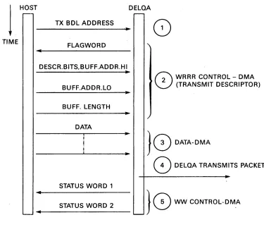
O'VERVIEW . . . . Transmit-Host to Ethernet Data Transmission .
Receive--Data Reception from Ethernet to Host REGISTER DEFINITIONS . . . .
Control and Status Transfers . . . .
Control and Status Registers . . . . Control and Status Register (CSR) Definitions . . . . Vector Addresses . . . .
Vector Address Register (VAR) Definitions . . . . BDL Start Address Registers (BDL SARs) . . . . . . Station Address Registers (SA ROM) . . . . HOST MEMORY DATA STRUCTURES . . . .
Receive and Transmit Buffers ..
Buffer Descriptor Lists (BDLs) . . . . Buffer Descriptor Bit Definitions . . . .
Flag Word . . . . Address Descriptor Bits. . . . . . . .
Buffer Address. . . . . . . Buffer Length (Word Count) . . . .
Status Words. . . . . . . DATA TRANSFER PROCEDURES
Transmit Packet . . . . Transmit Programming . . . . Transmission Errors . . . . . " . . Receive Packet . . . . .
Receive Programming . . . . Receive Errors . . . .
3.6 CONFIGURATION AND CONTROL PROCEDURES
3.6.1 Boot/Diagnostic Load. . . .
3.6.2 3.6.2.1 3.6.2.2 3.6.2.3 3.6.2.4 3.6.3 3.6.4 3.6.5 3.6.6 CONTENTS
Setup . . . .. 3-29 Setup Packets . . . 3-29 Setup Information . . . .. 3-29 Setup Packet Buffer Descriptor . . . .. 3-30 Setup Packet Format . . . 3-31 Reset . . . .. 3-34 Interrupt Handling . . . , . . . .. 3-35 Loopback. . . .. 3-35 Sanity 'rimer . . . .. 3-36 3.7 MAINTENANCE OPERATIONS PROTOCOL (MOP): MODULE SUPPORT . . . 3-36 3.7.1 Internal Loopback . . . .. 3-37 3.7.2 MOP Element Blocks (MEBs). . . .. 3-37 3.7.3 MOP Element Type 0: MOP Termination. . . .. 3-38 3.7.4 MOP Element Type 1: Read Ethernet Address. . . .. 3-38 3.7.5 MOP Element Type 2: Reset System ID. . . .. 3-41 3.7.6 MOP Element Type 3: Read Last MOP Boot. . . .. 3-41 3.7.7 MOP Element Types 4, 5: Read, Write Boot Password . . . .. 3-41 3.7.8 MOP Element Type 6, 7: ReadIWrite System ID . . . .. 3-41 3.7.9 MOP Element Types 8, 9: Read, Read/Clear Counters . . . 3-45
CHA~PTER
4 MAINTENANCE
4.1 4.2 4.2.1 4.2.2 4.2.3 4.2.4 4.3 4.3.1 4.3.2 4.3.2.1 4.3.2.2 4.4 4.4.1 4.4.2 4.4.3 4.4.3.1 4.4.4 4.5 4.5.1 4.5.2 4.6 4.6.1 4.6.2 4.7 4.7.1 4.7.2 4.7.3SCOPE . . . " ..
MAINTENANCE PHILOSOPHY . . . . Preventive Maintenance . . . " . . . Corrective Maintenance . . . . Field Replaceable Units (FRUs) . . . . Diagnostic Procedure . . . . SELF-TEST . . . . Extended Primary Bootstrap . . . . Citizenship Test . . . . Citizenship Test Descriptions . . . . Citizenship Test Results . . . .
4-1 4-3 4-3 4-3 4-3 4-4 4-5 4-5 4-6 4-6 4-8 MAINTENANCE OPERATIONS PROTOCOL (MOP): NETWORK SUPPORT . . . . .. 4-11 MOP Remote Console Message: Request System ID . . . .. 4-11 MOP Remote Console Message: System ID . . . 4-12 MOP Remote Console Boot Message . . . 4-15 Processing a Remote Message . . . .. 4-17 Ethernet Channel Loopback Protocol Support. . . .. 4-18 IEEE 802.3 NETWORK SUPPORT: NULL LINK-LAYER SERVICE ACCESS
CONTENTS
Appendix A
VECTOR ASSIGNMENTS
A.l A.2
The Floating Vector Assignment . . . . FLOATING VECTORS
Appendix B Diagnostics
lB.l lB.2 lB.2.1 lB.2.1.1 lB.2.1.2 lB.2.1.3 1B.2.2 13.3 13.4 B.5 13.5.1 13.5.1.1 13.5.1.2 B.5.1.3 13.5.1.4 13.5.2 B.6 B.7 B.7.1 B.7.1.1 B.7.1.2 B.7.2 B.S B.S.l B.S.1.1 B.S.I.2 B.S.1.3 B.S.2 B.9 B.9.1 B.9.2 B.9.3 B.I0 B.IO.l B.I0.2 B.I0.2.1 B.I0.2.2 B.IO.2.3 B.IO.3 B.ll B.I1.1 Rl1.2SCC)PE . . . . OPERATING ENVIRONMENTS . . . . PDP-ll Diagnostic Runtime Services (DRS) . . . . DRS Commands. . . . . . . DRS Switches . . . . DRS Flags . . . . Micro VAX Diagnostic Monitor (MDM) . . . . NETWORK INTERCONNECT EXERCISER (NIE) . . . . INTRODUCTION . . . . OPERATING MODES. . . . Unattended Mode . . . . Build Node Table . . . . Direct Loop Message Test. . . . Pattern Test . . . . Multiple Message Activity Test . . . . Operator Directed Mode . . . . SYSTEM REQUIREMENTS
COMMAND DESCRIPTION
DRS Commands . . . . Switches . . . . :Plags . . . . NIE Commands . . . . ERRORS . . . .
I~rror Messages . . . . General . . . . Basic . . . :. Extended . . . . Other Error Messages . . . . PDP-II FUNCTIONAL DIAGNOSTIC (ZQNA??) . . . . ZQNA?? Environment . . . . ZQNA?? Test Descriptions . . . . ZQNA?? Error Reports . . . . MicroVAX DIAGNOSTIC MONITOR (MDM) . . . . MDM Environment . . . . MDM Service Test Descriptions . . . . Verify Mode Tests. . .' . . . . Field Service Functional Tests . . . . Field Service Exerciser . . . . MDM Utilities. . . .. DEC/Xll EXERCISER . . . .
Environment . . . . Command Descriptions . . . .
vi A-I A-I B-1 B-1 B-1 B-2 B-2 B-3 B-4 B-5 B-5 B-5 B-5 B-6 B-6 B-6 B-6 B-6 B-7 B-7 B-7 B-S B-9 B-ll B-20 B-20 B-20 B-20 B-20 B-21
, B-21
App~endix (~
PROGRAMMING EXAMPLES FOR PDP-11
SYSTEMS
C.l C.2 C.3 C.4 C.5 C.6 C.7 C.8INDl8:X
1-1 1-2 1-3 1-41-5
1-6 1-7 2-1 2-2 2-3 3-1 3-2 3-3 3-4 3-5 3-6 3-7 3-8 3-9 3-10 4-1 4-2 4-3 4-4 4-5 A-I B-1 B-2 B-3 B-4Data Definitions
Resetting the DELQA . . . . Configuring the DELQA . . . . A Simple Interrupt Handler . . . . .
Data transmission. . . . Data reception . . . . Executing on-board diagnostics. .
BUFFER DESCRIPTOR MANAGEMENT ALGORITHM . . . .
Typical Ethernet Configuration . . . . Warnings . . . . Warnings . . . .' .. Ethernet Connectivity . . . . Ethernet Packet (Frame) Format . . . . DELQA Functional Block Diagram . . . : DELQA Module Board Layout. . . . DELQA Switches in Default Position and LEDs. . . . . . . Rear Panel, Bulkhead, Blanking Panel, and Modules . . . . DELQA Cabinet Kits . . . . Transmit Sequence (No Chaining) . . . .
Host I/O Page Map. . . . Control and Status Register (CSR) . . . . Vector Address Register (VAR) . . . . BDL Start Address Registers . . . .
Buffer Descriptor Format . . . .. . . . . . Ethernet Packet Format . . . . Setup Packet Format (Bytes) . . . . MOP Element Block Buffers in the Setup Packet . . . . MOP Element Block Types 1 to 9 . . . . Field Replaceable Units (FRUs) . . . . Request ID Message Format .. . . . System ID Message Format. . . . . . . . Boot ID Message Format .' . . . . Loop Message Format . . . . Q-bus Address Map . . . . Loop Direct Messages Test Path . . . .
Transmit Assist Loopback Message Test Path Full Assist Loopback Message Test Path . . . Receive Assist Loopback Message Test Path .
CONTENTS TABL]~S 1·-1 1·-2 }'-3 1·-4
1·-5
1·-6 2·-1 2·-22·-3
J-l J-2 3·-3 3·-4 J-5 3·-63·-7
J-8 3·-9 3·-103·-11
J-12 4-1 4-2 4-3 4-4 4-5 4-6 A-IB-1
B-2 B-3B-4
B-5
B-6B-7
B-8 B-9 B-I0 C-lField Sizes in an Ethernet Packet DELQA Ordering Options . . . . Module Addresses . . . .
BNE3x-nn Transceiver Cable Options. DELQA Cabinet Kit Connections DELQA Specifications . . . .
DELQA Installation Parts List .. Module Address and Vectors . . . Module LED Sequences . . . . DELQA Unit I/O Base Addresses .
Control and Status Register (CSR) Normal Mode Usage . . . . . Vector Address Register (VAR) . . . . Setup Packet: Information Group Combinations . . . . Setup Packet Buffer Descriptor: Address Mode Bits . . . . Effects of Reset on Setup Packet Data . . . . . . . MOP Functions . . . .
MOP Element Type 1 . . . MOP Element Types 4, 5 . MOP Element Types 6, 7 .
Infonnation Value Descriptions . . . .
MOP Elements Type 8, 9 MEBB Format . . . . Citizenship Test: Error Bit Definitions . . . . Maintenance Operation Protocol (MOP) Messages . Request ID Message Format
System ID Message Format. Boot ID Message Format . .
Loop Message Format . . .. . . . . Floating Vector Address Assignments . . . . Diagnostic Runtime Services (DRS) Commands. Command Switches .
Switch Application . . . . Flags Application . . . . DRS Commands . . . . . DRS Command Switches Switch Application . . . .
DRS Command Flags . . . . NIE Commands. . . .
DELQA DEC/X 11 Exerciser Software Register Bits Data Definitions for Sample Programs. . . .
PREF1\CE
INTRO][)UCTION
The DELQA module is a communications option which connects the Q-bus to an Ethernet local area network (LAN).
This manual describes how to install, program, and maintain the DELQA. It contains information for first-time servicing and field-service support, and for customer engineers and programmers.
The chapters are as follows.
Chapter 1 introduces the Ethernet LAN and the DELQA module.
Chapter 2 describes how to install a DELQA module.
Chapter 3 describes how to program the DELQA.
Chapter 4 describes how to use the diagnostic utilities to maintain the module
Appendix A details the DELQA vector address and assignments.
Appendix B summarizes commands and facilities for the DELQA diagnostics.
Appendix C gives examples of host software programming of the DELQA.
Appendix D gives details of DELQA responses to undesired events.
Appendix E is a glossary.
This revision of the manual contains new information and Chapter 3 has been expanded to contain additional programming notes.
Notes alild Warnings
NOTES and WARNINGS are defined as follows. A NOTE contains general information.
A VVARNING is designed to prevent personal injury. Related Publications
Communications Options Mini-Reference Manual: Volume IV (Ethernet) (EK-CMIV4-RM)
DECnet Maintenance Operations Protocol (MOP) Functional Specification V3.0.0 (AA-X436A-TK)
DECnet·RSX System Manager's Guide (AA-H224C-TC)
DECnet--ULTRIX Guide to Network Management (AA-EE38A-TE)
DECnet--VAX System Manager's Guide (AA-H803C-TE)
Preface
DELQA Field Maintenance Print Set (MP-02379)
DELQA Technical Description (EK-DELQA-TD-OOl)
Ethernet: A Local Area Network, Data Link Layer, and Physical Layer Specifications (AA-K759B-TK)
Ethernet Installation Guide (EK-ETHER-IN)
H4000 Ethernet Transceiver Technical Manual (H4000-TM)
Introduction to Local Area Networks (EB-22714-18)
MicoPDP-ll Systems Service Maintenance Guide (EK-MICll-SG)
MicroVAX 11 System Maintenance Guide (AZ-GM3AA-MN)
Network Interconnect Exerciser Diagnostic (AC-T585A-MC)
XXDP+ISUPR User's Manual (AC-P348A-MC)
NOTE
When installed in a Micro-PDPll or a MicroVAX, this equipment has been tested with a Class A computing device and has been found to comply with part 15 of FCC Rules. Operation in a
residential area may cause unacceptable interference to radio and TV reception requiring the operator to take whatever steps are necessary to correct the interference.
CHAPTER!
INTRODUCTION
1.1 SCOPE
This chapter introduces the M7516 module, which is a DIGITAL Ethernet Local-Area-Network to Q-bus Adapter (DELQA). The sections are as follows.
Section ll.2 Ethernet Overview
Section ll.3 DELQA Overview
Section ll.4 Specification
Section ll.5 Interfaces
Section 1l.6 Functional Description
1.2 ETHERNET OVERVIEW 1.2.1 General Description
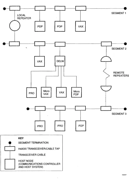
Ethernet employs a branching-bus topology, with all nodes granted equal access rights. Using repeaters, the main bus can be extended up to 2.8 kilometers (1.74 miles) between the two furthest nodes of the network. Along this length, up to 1024 nodes can be tapped into the network.
Each node is a single addressable entity, comprising a controller and a transceiver. The transceiver is connected to the Ethernet cable by a cable tap. The cable that connects the transceiver to the controller can be up to 50 meters long. The transceiver itself is not always necessary; for example, the connection to the Ethernet may be made using a DELNI multiplexer.
INTRODUCTION
-R
PDP
VAX
PRO
PRO
KEY
1
I
I
1
Micro VAX
SEGMENT TERMINATION
1
I
PDP
I
DELNI
VAX
I
PRO
H4XXX TRANSCEIVER/CABLE TAP
TRANSCEIVER CABLE
HOST NODE
(COMMUNICATIONS CONTROLLER AND HOST SYSTEM)
1
I
I
I
1
I
r
I
VAX
Micro PDP
J I
PDP
1 I
I
Figure 1-1 Typical Ethernet Configuration
1-2
•
SEGMENT 1
I I _
[image:12.615.98.531.76.685.2]1
... - - . - - - 11 - .
( \
SEGMENT 2
REMOTE REPEATERS
I 1 _
' - - _ ... 1 . . ,
SEGMENT 3
INTRODUCTION
WARNING
Ethernet installations may extend to thousands of meters and couple hundreds of separate items of equipment. To prevent hazardous voltages a)Jpearing on the installation, it is important that all the equipment be part of a cOinmon equipotential bonding system as defined in IEC publication 364-4-41 clauses 413.1.2 and 413.1.6. Where it is required 0 couple equipment outside of the main equipotential
bonded arEIa via ethernet, then optical repeaters or other such galvanically isolated measures must be employed. If in doubt please refer to Digital for advice.
VAROITUS
Ethernet-verkot voivat ol1a tuhansia metrejii pitkiii ja niihin voidaan liittiiii satoja erilaisia laitteita. Jotta verkkoon ei piiiisisi syntymiiiiJ1l vaarallisia jiinnitteitii, kaikkien laitteiden on ehdottomasti kuuluttava samaan potentiaalintasausjiirjestelmiiiin, jonka ominaisuudet on miiiiritetty IEC:n julkaisussa 364-4-41, kohdissa 413.1.2 ja 413.1.6. Mikiili Ethernetiin halutaan liittiiiilaite, joka ei kuulu potentiaalintasausjiirjestelmiiiin, on kiiytettiiviioptisia toistimia tai vastaavia galvaanisesti eristettyjii menetelmiii. Jos et ole varma kiiytettiiviistii menetelmiistii, ota yhteys Digitaliin.
DANGER
Une installation Ethernet peut s'etendre sur des kilometres et relier des centaines d'eIements. Afin d'eviter tout probleme electrique, verifiez la l~resence d'une mise
a
la terre commune ainsi qu'elle est definie par l'IEC (364.4.41, clauses 413.1.2 et 413.1.6). S'il s'avere necessaire de relier par. Ethernet des equipements non rattachesa
une meme terre, utilisez des repeteurs optiques ou autres materiels offrant la meme qua lite d'isolation. En cas de doute, prenez contact avec les Services techniques Digital.VORSICHT
Ethernet-Netzwerke konnen sich uber mehrere tausend Meter erstrecken und mehrere hundert einzelne Gerate miteinander verbinden. Zur Vermeidung von gefiihrlichen Spannungen im Netzwerk ist es unbedingt erforderlich, daB aIle Geriite Teil einer gemeinsamen Erdungsschleife sind, wie in den IEC-Richtlinien 364-4-41, Abschnitte 413.1.2 und 413.1.6 angegeben. Wenn Geriite auOerhalb der Erdungsschleife iiber Ethernet miteinander verbunden werden mussen, mussen optische Repeater oder andere galvanisch getrennte Mittel verwendet werden. Falls Sie Fragen haben, wenden Sie sich an Digital Equipment.
WAARSCHUWING
Ethernet-configuratie!~ kunnen een afstand van verschillende kilometers overbruggen en honderden afzonderlijke apparaten met elkaar verbinden. Om te vermijden dat er zich gevaarlijke spanningen zouden voordoen op de configuratie, is het belangrijk dat aIle apparatuuJr gebruik maakt van dezelfde voeding en dezelfde aarde, zoals gedefinieerd in de IEC-publikatie 364-4-41, bepaUngen 413.1.2. en 413.1.6. Wanneer apparatuur die niet op eenzelfde equipotentiaal spanningsnet is aangesloten via Ethernet gekoppeld moet worden, moet men gebruik maken van optische repeaters of van andere galvanisch isolerende technieken. Bij twijfel gelieve u contact op te nemen me't Digital.
ATTENZIONE
Le installiltzioni Eth(~rnet possono estendersi per migliaia di metri e collegare diverse centinaia di elementi separati di apparecchiiature. Per evitare il rischio di scariche elettriche al momento dell'installazione, e importante che tutte Ie apparecchiature siano colle gate ad un comune sistema di massa come definito nella pubblicazione IEC 364-4-41, claus ole 413.1.2 e 413.1.6. Laddove si richieda di collegare l' npparecchi81tura fuori dalla principale area di massa via Ethernet, si devono utilizzare ripetitori su fibra ottica 0
qualsiasi altro strumento isolato gslvanicamente. Per qualsiasi informazione rivolgersi alIa sede Digital piu vicina.
ADVARSEL
Ethernetinstallasjonel' kan strekke seg over flere tusen meter og ha tilkoblet flere hundre forskjellige utstyrsenheter. For A forhindre at det skal oppstA farlige spenninger pA installasjonen, er det viktig at alt utstyret tilhorer et felles ekvipotensialt forbindelselsystem, slik det er definert i IEC-publikasjon 364-4-41, paragrafene 413.1.2 og 413.1.6. Der hvor det er pakrevet A koble utstyr via Ethernet utenfor det ekvipotensiale hovedomrAdet, er det pabudt a benytte optiske linjeforsterkere (repeatere) eller tilsvarende galvanisk isolert materiale. Kontakt Digital hvis du er i tvil.
INTRODUCTION
ATENCION
Las instalaciones bnsadas en Ethernet pueden cubrir areas de varios centenares de metros e interconectar distintos modulos de un equipo.Para evitar que se den tensiones peligrosas en la instalacion es necesario que todos los componentes.se conecten a una masa imica, de acuerdo con normas IEC 364-4-41 (§413.1.2 y §413.1.6). Cuando sea preciso utilizar Ethernet con componentes que no vayan conectaldos a dicha JDasa COJDun se utilizarlm repetidores opticos u otros dispositivos de medida con aislamiento galvanico. En caso de duda con suIte con ))igital.
VARNING
Ethernet-installationer kan omfatta tusentals meter kabel som kopplar samman hundratals separata delar av en utrustning. For att skadligul spiinningall' ska undvikas iir .det viktigt att all utrustning har gemensam jord enligt vad som anges i IEC:s skrift 364-4-41, avsnitten 413.1.2 och 413.1.6. Diir det iir nodviindigt att ansluta utrustning med annan jordning via Ethernet, maste optiska kopplare aJ;lviindlils eller and.'a atgiirder vidtas for att astadkomma galvanisk isolering. Kontakta giirna Digital lor ytterligare information.
AVISO
A instahl~iio da Ethernet pode estender-se por milhares de metros e agrupar centenas de itens de equipamento.
Para evitar que vohagens perigosas surjam na instala~iio, e import ante que to do 0 equipamento faca parte de um sistema electrico equipotElncial comum, tal como definido na publica~iio 364-4-41 do IEC, clausulas 413.1.2 e 413.1.6.
Onde fOlr necessario ligar equiIJamento fora da area principal de Iiga~iio electrica equipotencial, atraves da Ethernet, deverao ser empregues repetidores opticos ou outras solu~oes galvanicamente isoladas.
Em caso de duvida, contacte a Digital.
ADVARSEL
Ethernet-installationer kan strrekke sig over tusindvis af meter og forbinde hundredevis af separate dele af udstyr. For at undga farlig spronding i installationerne er det vigtigt, at alt udstyret er del af et frolles jordingspunkt som defineret i IEC publikation 364-4-41, klausulElrne 413.1.2 (JIg 413.1.6. Hvor det er nodvendigt at forbinde udstyr udenfor det storre frolles jordingspunkt via Ethernet, skal der anvendes optisk kobling eller anden form for galvanisk isolering af udstyret. For yderligere oplysninger henvises til den lokale Digital afdeling,
1~1 ,D~'Un ~~JN ~f~ JU D~nU~J nlu'n~n ETHERNET-~ nlfpn~ D~nnD UltOJ ~'J .D~,,~t '1'~ ~U~,~ nlNO nOJ J1JJJ nlJ1JU
'1~~~ JJ~ ,~~pnJ j1~n
'Nn
,1PnnJ ntJO nllnJ D~J1JU~ D"Jn~n l~~ n'Jnnnl ntJO lnlNJ nN~nt~ n~n1~n JO~n nJ,unn PJn nl1~~019, ,J, ,IEC -J "lln~ ~~J ,'N~~fU1~Jl nJJ D'll~n 1~'J'J'n .413.1.6 -1 413.1.2 D~~~UO 364-4-41 nN JJ1J~ nfJoJ ~1no 'l'~ 'U"~ l'J 'JnJ ~"f DnJ~ nlnlpnJ ~nnV~J D'J~'n 'TN ,ETHERNET nlU~nNJ ,n~nl~nn n'~N'n JO~nn nJ'Un D',nN D'U~ONJ IN (OPTICAL REPEATERS, BRIDGES) 'U~1N 'l'~J
.~nJnn ~~, D"'1Jnn .J"pn JU'l" "~OJ nlf~J Nt ,nlp~O l"1Un'1 n"OJ
-1 - -tt
-r, ,"
I, V'>~;t foir tj: tt r-;;< - 11 ( . .: & k t.:,' f) ,3::":'
c
i;'J') I) ;t T~\tOCU':~T~~r'9P;;:'~T-fV'>"ft4.l:-M <"t.:/lht.:tj:, IE C' '~¥N 3 ti -1 - -1- -1 1 V'. >
~ Jij . j 1 3. 1 . :2, tj J: r,Y·1 1 3. 1 , (, t.: n:: /fh t~ ;h -C v 1 0 J: "') t.:, Lf!: -C V') tI!t ~ 1;'
cttilli t~tl!! s.- ;<. 'T.1, (.: t~*'~ ;2\ ;/L -C v I ~, ..:. .J;:: 1;"1II. ~ "(" T .
~jjjH~tl!!s.- .;<. 'T.1, I,.:t~m"(" ~ ~: v d~fiJf ( (I!!.V'> c',t,. W) (..: -1 - +t t, '" I, 1:-(7" L ~(tI!t
mi 1:-~~ iii T 0 ,e·~ 1;> J) ~) :l:~ ;S;-, -:t 7' + II ,t- I} l:::: - 11, ~ -t::. tj: ~ 51\ A'.J ( . .:
n'
/lift ~ i l t::.=f. f~ 1: ~A t 0 ..:.l;:: I;ce, ~ -C"
-,J-Figure 1-3 Warnings
1-4
INTRODUCTION
The principal characteristics of the Ethernet are:
Topology: Branching bus
Medium: Shielded coaxial cable
Transmission: Manchester-encoded digital baseband signaling
Data Rate: 10 Megabits/second.
Access Control: Carrier Sense, Multiple Access with Collision Detect (CSMA/CD).
Allocation: 64- to 151S-byte packet length (includes variable-length data field between 46 and 1500 bytes).
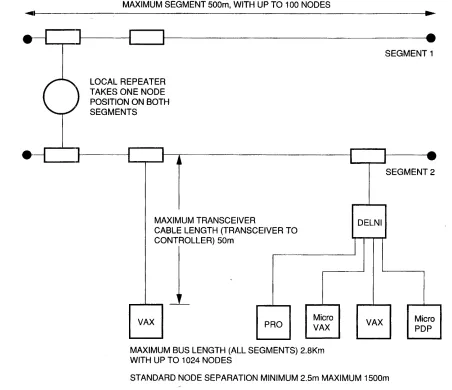
The maximum Ethernet configuration for a coaxial cable bus is as follows:
Each segment of coaxial cable can be up to 500 meters long (1640.5 feet). Each segment must be terminated at both ends.
Up to 100 nodes can be tapped into a cable segment. Each node must be between 2.5 meters (S.2 feet) and 1500 meters (4921.5 feet) from its nearest neighbors. Standard transceiver positions are usually marked at every 2.5 meters.
A transceiver cable (from transceiver to node controller) can be up to 50 meters (164 feet) ~ong.
Repeaters are used to retransmit signals from one segment to another. A repeater uses a node position, and also contributes to the total node count, on both the segments that it connects. There can be up to two repeaters in the path between any two nodes.
Repeaters can be placed at any position along a cable segment to extend the network bus up to a maximum of 2.S kilometers (1.74 miles). This would comprise three segments of 500 meters, plus six transceiver cables of 50 meters, plus a 1 km fiber cable between remote repeaters.
The Ethernet configuration rules ensure the best network performance within physical channel limitations. Figure 1-4 shows the limits of Ethernet connectivity.
1.2.2 Ethernet Luyers
The Ethernet architecture is structured in two layers which correspond to the lowest layers in the International Standards Organization (ISO) model for Open Systems Interconnection (OSI).
The two layers have the following functions.
The physical layer specifies the maximum number of nodes, their maximum separation, the data rate on the Ethernet bus, as well as the electrical and mechanical connections.
The data link layer specifies the mechanism for access control (CSMA/CD), the procedure for multiaccess network control, and the format of transmission packets.
The physical layer and the data link layer together provide a datagram service for transmitting message packets between nodes. A datagram service cannot guarantee that a packet is received, because transmission and reception are the responsibility of higher levels in the network· architecture; but it does guarantee that those packets that are received are correct.
INTRODUCTION
MAXIMUM SEGMENT 500m, WITH UP TO 100 NODES
~~I ---~.~
•
•
~-J~---~~--Ji---~.
SEGMENT 1 LOCAL REPEATER
TAKES ONE NODE POSITION ON BOTH SEGMENTS
____ ]I---IIL-.-r---II
j ~MAXIMUM TRANSCEIVER
CABLE LENGTH (TRANSCEIVER TO _",,--C_OILLERl SOm
VAX PRO Micro
VAX MAXIMUM BUS LENGTH (ALL SEGMENTS) 2_8Km WITH UP TO 1024 NODES
r I _
1
... - - . - - - 11 . .
DELNI
1
VAX
SEGMENT 2
Micro PDP
STANDARD NODE SEPARATION MINIMUM 2.5m MAXIMUM 1500m
RE6898
Figure 1-4 Ethernet Connectivity 1.2.3 Data Encapsulation
Data is transmitted over an Ethernet in packets (or frames) that have a specific format.
Figure 1-5 shows the format of an Ethernet packet. Table 1-1 gives the size of each field in an Ethernet packet.
[image:16.612.78.530.74.464.2]INTRODUCTION
Table 1--1 Field Sizes in an Ethernet Packet
Field Bytes
Destination 6
Source 6
Type 2
Data 46 to 1500
CRC 4
Total packet 64 to 1518
A packet is preceded by a 64-bit preamble which is a pattern of alternating 1 s and Os for receiving node synchronization. The pattem ends with ... 01011 rather than ... 01010.
The fields in the packet are as follows.
1. The destination field contains the 48-bit address of the receiving node(s). The address is either physical or
logical, and it may be anyone of the following. An individual node address (first address bit = 0)
A multicast address for a group of nodes (first address bit =1). A broadcast address for all nodes (all address bits = 1).
2. The source field contains the 48-bit Ethernet physical address of the sending node.
3. The 16-bit type field determines how higher-level software interprets the data field.
4. The; protocol data field itself must contain between 46 and 1500 bytes. If the data to be sent consists of less than 46 bytes. software must insert null bytes to fill the field.
5. The: frame check sequence (FCS) contains a 32-bit Cyclic Redundancy Check (CRe) value. The DELQA
module calculates this value, inserts it when a packet is transmitted, and checks it when a packet is received. The: CRe is removed from a received packet before delivery to the host.
The intelframe spacing (or interpacket gap) allows the physical channel to recover between packets. The
minimum spacing is 9.6 microseconds.
Figure 1l-3 shows the standard Ethernet packet format.
C
PREAMBLE8 BYTES
DESTINATION
6 BYTES
SOURCE
6 BYTES
DATA CRC IINTERFRA~lE1
____ ~~ ______ ~_G~~ ____
J
2 BYTES 4 BYTES
BETWEEN 46 AND 9.6 MICROSECONDS
1500 BYTES (MINIMUM)
----TOTAL SIZE OF PACKET IS BETWEEN 64 AND 1518 BYTES
-RE1679
INTRODUCTION
1.3 UELQA OVERVIEW 1.3.1 ~(;eneral Description
The Q-bus communications controller on the DELQA module interfaces both the MicroVAX and LSI-ll families of prooessors to an Ethernet Local Area Network (LAN). The controller is compatible with both 18- and 22-bit Q-bus backplanes.
The DELQA module conforms to the Ethernet specification (Version 2.0), and is compatible with the IEEE
802.3 Specification for Carrier Sense with Multiple Access with Collision Detection. In terms of Open Systems
Interconnection, the module implements the functions of the physical layer and part of the data link layer. The principal functions of the DELQA module are to:
Transmit/receive data at 10 Mbits/s
Penform packet serialization, formatting, Manchester encoding, and multiple retransmission Generate and check a 32-bit CRC for each packet
Interface with the Ethernet transceiver
Perform Direct Memory Access (DMA) transfers to and from host memory DELQA (Normal lVlode) also supports:
Generation of MOP Remote console system ID message Processing MOP Remote console system ID requests Processing of Ethernet channel loop back protocol requests Processing of MOP Remote console BOOT requests
Processing of IEEE 802.2 NULL LSAP XID message requests Processing of IEEE 802.2 NULL LSAP TEST message requests.
Writl~ the MOP Boot Password value Readl the MOP Boot Password value Write the MOP System ID Parameters Read the MOP System ID Parameters Resell the MOP System ID Parameters
Read the last MOP Remote Boot message received Read the datalink counters values
Read and clear the values of the datalink counters Read the current DELQA Physical Ethernet Address On-Board (OBT) self-test:
Execution on Power-Up Host software request bit
Completion status with error report Boot/diagnostic code support.
Switches are provided on the DELQA module for setting the Q-bus base address, the operating mode (Normal or DEQNA-Iock), and various operating conditions (such as Remote Boot). Other functions and configurations are programmable from the host.
INTRODUCTION
The DELQA module has an on-board self-test that is independent of the host. On-line and standalone diagnostics are also available. Three LEDs on the module indicate the test status of the module.
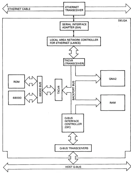
Figure 1-6 shows the functional block diagram of the DELQA.
1.3.2 Physical Description
The DELQA module is a dual-height module which plugs directly into the Q-bus backplane.
The DELQA module may be connected to the Ethernet physically and electrically using an H4xxx transceiver; or using a DELNI multiplexer and a transceiver. The connection is made through the cabinet kit and transceiver cable.
The cabinet kit consists of a bulkhead panel and cable which is manufactured as a single assembly.
1.3.3 Order Codes
The DELQA module consists of a base option (DELQA-M) and a cabinet kit (CK-DELQA-Yx). These options are ordere:d separately.
Table 1-2 lists the DELQA module options.
Table 1-2 DELQA Ordering Options Base Option
DELQA-~v1
CK-DELQA-YB
CK-DELQA-YA
CK-DELQA-YF
1.3.4 Q-bus Addresses
Description
DELQA Module M7516
BA23
BA123
H9642
DELQA User's Guide (EK-DELQA-UG)
12 inches (30.5 cm)
21 inches (53.6 cm)
36 inches (91.5 cm)
Each kit is supplied with a module-to-bulkhead cable of the appropriate length, and a 15-pin bulkhead loopback connector (12-22196-02).
Table 1-3 lists the Q-bus addresses that are available for use by a DELQA module.
Table 1-3 Module Addresses Base Address
17774440
17774460
Unit
DELQA 1
DELQA 2
Module
DELQA or DEQNA
INTRODUCTION
<
11L--______________
" ETHERNET CABLE ---1 TRANSCEIVER ETHERNETt - - - .
SERIAL INTERFACE ADAPTER (SIA)
LOCAL AREA NETWORK CONTROLLER FOR ETHERNET (LANCE)
en
:::>
m
h:'
~
~
~
' - - - 'a-BUS INTERFACE CONTROLLER (OIC)
L _ _ _ _
~
HOST a-BUS
DELOA
ONA2
RAM
<
;1
~~---~RE16BO
Figure 1-6 DELQA Functional Block Diagram
[image:20.615.95.542.78.669.2]INTRODUCTION
1.3.5 E,thernet Connection
A separate transceiver cable (order number BNE3X-nn), which must be ordered separately, connects the bulkhead to an Ethernet transceiver. This transceiver cable has a male 15-pin connector for fitting into the bulkhead.
NOTE
The signal connections of the DELQA cabinet kit comply with IEEE 802.3, and may be used with either the DELQA or DEQNA modules. DEQNA cabinet kits are not IEEE 802.3 compliant, and may only be used for Ethernet networks.
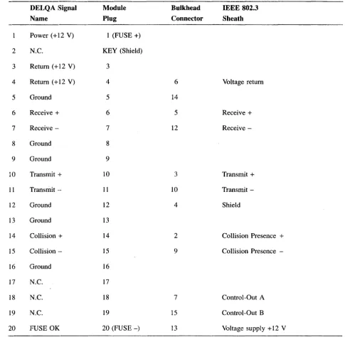
Table 1-4 lists the transceiver cable options. Table 1-5 lists the pin connections on the DELQA module and at the bulkhead.
Table 1--4 BNE3x-nn Transceiver Cable Options Option Material Connector
BNE3A PVC Straight
BNE3B PVC Right angle
BNE3C Teflon™ Straight
BNE3D Teflon Right angle
Part Number Length
-05/J2 16.4 ft (5 m)
-10/12 32.8 ft (10 m)
-20/J2 65.6 ft .(20 m)
-40/J2 131.2 ft (40 m)
INTRODUCTION
Table 1-5 DELQA Cabinet Kit Connections
DELQA Signal Module Bulkhead IEEE 802.3
Name Plug Connector Sheath
Power (+12 V) 1 (FUSE +)
2 N.C. KEY (Shield)
3 Return (+12 V) 3
4
Return (+12 V)4
6 Voltage return5 Ground 5
14
6 Receive + 6 5 Receive +
7 Receive - 7 12 Receive
-8 Ground 8
9 Ground 9
10 Transmit -I- 10 3 Transmit +
11 Transmit -- 11 10 Transmit
-12 Ground 12 4 Shield
13
Ground 1314
Collision -I-14
2 Collision Presence +15
Collision -- 15 9 Collision Presence-16 Ground 16
17 N.C. 17
18 N.C. 18 7 Control-Out A
19 N.C. 19 15 Control-Out B
20 FUSE OK 20 (FUSE-) 13 Voltage supply + 12 V
1.4 SlPECIFICATIONS
The DELQA module meets the Ethernet specification (Version 2.0) and is compatible with IEEE 802.3
Specification for Carrier Sense with Multiple Access with Collision Detection.
Table 1·-6 gives the specifications of the DELQA module.
[image:22.615.70.556.101.576.2]INTRODUCTION
Table 1-6 DELQA Specifications Physicul
Electrical
Qnbus loads
Temper,ature
Airflow
Relative Humidity
Dimension Imperial Metric
Height 5.19 inches 12.67 cm
Width 0.5 inches 1.27 cm
Length 8.94 inches 22.6 cm
Weight 12 ounces 0.34 kg
Voltage Tolerance Typical current
+5.0 V ±5% 2.7 A
+12.0 V ±5% 0.5 A
AC DC
3.3 0.5
Environment Specification
Storage - 40 to 66 degrees Celsius
Operation 5 to 50 degrees Celsius
NOTE
BEFORE OPERATING with the DELQA module you must give it a reasonable time to stabilize in an environment within the operating range.
Specification
Maximum current
3.0A
1.5 A
Airflow across the board must limit the outlet temperature to a maximum of 50 degrees Celsius, and the temperature rise across the board to 10 degrees Celsius.
Under typical power dissipation, this can be achieved using a linear airflow of 1.2 meters/second.
NOTE
Do not subject any area of the board to a local ambient temperature above 70 degrees Celsius under any environmental conditions.
Environment Specification
INTRODUCTION
Table 1-6 (Cont.) DELQA Specifications Relative Humidity
Altitude
Environment Operation
Environment
Storage
Operation
Specification
10% to 95%, non-condensing
Specification
Maximum: 12.1 km (40,000 ft) Maximum: 2.4 km (8,000 ft)
NOTE
Derate the maximum operating temperature by 1.8 degrees Celsius for each 1000 meters (3281 feet) of altitude, unless constant cooling is provided.
---,---1.5 THE DELQA MODULE FUNCTIONAL DESCRIPTION 1.5.1 General Description
The DELQA module is a Q-bus communications option which enables higher-level software protocols, such as DECne1:, to communicate over an Ethernet network.
The DELQA module conforms to the Ethernet Local Area Network Specification (Version 2.0), and is compatible with tht~ IEEE Specification 802.3 for Local Area Networks.
The DELQA module transfers encapsulated data packets of 60 to 1514 bytes between buffers in host memory and an Ethernet transceiver. The DELQA module appends a 4-byte CRC to transmit packets, making the length of the packet on the Ethernet between 64 and 1518 bytes. The DELQA module strips the 4-byte CRe from received packets"
Transmitt packets are transferred from host memory to buffer memory (shared RAM) on the DELQA module board, and from there on to the Ethernet. ~eceived messages follow the same path in the opposite direction. The DELQA module is programmed from the Q-bus using eight word addresses in the I/O page, and can perform block-mode DMA to and from Q-bus memory. In addition to providing an Ethernet interface, DELQA supports some functions of the Maintenance Operations Protocol (MOP).
1.5.2 Operating Modes
The DELQA modlule operates in one of two modes. DELQA (Normal mode) supports:
Th(~ provision of DEQNA compatibility when using DIGITAL software drivers Generation of MOP Remote console request system ID requests
Processing of MOP Remote console system ID requests Processing of Ethernet channel loopback protocol requests Processing of MOP Remote console BOOT request
Processing of IEEE 802.2 NULL LSAP XID message requests Processing of IEEE 802.2 NULL LSAP TEST message requests. Write the MOP Boot Password value
Read the MOP Boot Password value
Write the MOP System ID Parameters Read the MOP System ID Parameters Reset the MOP System ID Parameters
Read the last MOP Remote Boot message received Read the datalink counters values
Read and clear the values of the datalink counters Read the current DELQA Physical Ethernet Address On-Board self-test:
Powerup execution in DELQA mode Host software request bit
Completion status with error report Boolt/diagnostic code support.
INTRODUCTION
In DEQNA-lock mode, the DELQA module provides functional compatibility with DEQNA modules when using some non-DIGITAL software drivers.
1.5.3 Host Programming
The DELQA module handles block-mode DMA automatically, once the buffers and control information have been set up by host software.
Host software is responsible for:
Initializing the communications data area in host memory Writing a setup packet with information to initialize the DELQA
Handling interrupts generated by DELQA, particularly on completion of each transmit or receive DMA transfer.
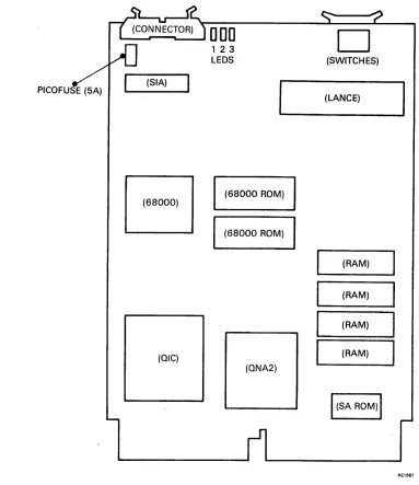
1.5.4 M:odule Components
Figure 1··7 shows the major components of the DELQA module. Processor subsystem
LANCE/SIA subsystem QIC
QNA2
Memory subsystem
INTRODUCTION
PICOFUSE (5A)
' - - - r - - - t . - - - '
D
[JO
(SIA)
B
(OIC)
123
LEOS
(68000 ROM)
(68000 ROM)
(ONA2)
D
(SWITCHES)
(LANCE)
(RAM)
(RAM)
(RAM)
(RAM)
liSA
ROM)IFigure 1-7 DELQA Module Board Layout 1.5.5 Processor' Subsystem
The M68000 CPU plus firmware is responsible for:
AE1681
Self-test and initialization upon power-up and reset. Self-test verifies the integrity of each of the five functional subsystems. plus the integrity of the cable signal path from the DELQA module to the Ethernet transceiver.
Managing all module configuration and control functions in accordance with the CSR and Setup packet parameters.
Managing all data transfer functions. including initiation of DMA transfers to/from host memory by giving the appropriate instructions to the QIC.
Network management support including MOP and IEEE 802.2 functions.
[image:26.612.107.490.87.530.2]1.5.6 LANCE/SIA Subsystem
The LANCE/SIA chipset is responsible for:
CSMIA/CD network access, including collision handling Packet serialization/deserialization
CRC generation/checking Framing
Data encapsulation Buffer management On-board DMA Error reporting
INTRODUCTION
Address detection can be programmed to detect a specific physical address, or logical addresses.
1.5.7 QIC Subsystem
The QIC is a general-purpos(~ Q-bus interface controller which provides: Q-bus slave control logic
I/O page addressing
DMA arbitration and control:
On Q-bus side, both control-DMA (four words mixed writes and reads), and data DMA, 22-bit addressing
On backport side, 16-bit DMA address register/counter Inten-upt control
Q-Bus NXM timeout detection The ability to initiate host reboot.
1.5.8 QNA2 Subsystem
The QNA2 arbitrates requests (R/W access, and DMA) for the backport bus, which is shared between the QIC, 68000, and LANCE. The QNA2 implements the following control functions.
Arbitration of access rights for the QIC, 68000 microprocessor and LANCE Read/Write control logic for memory accesses
Read/Write control logic for QIC registers, LANCE registers LANCE and QIC contro]
68000 control
INTRODUCTION
1.5.9 Memory Subsystem The memory subsystem contains:
32K bytes of static RAM for packet buffering, and scratch area for 68000
32K bytes of Firmware ROM, which also includes the self-test diagnostic code. The firmware ROM also contains 4.0K bytes of PDP-ll boot/diagnostic code for execution by the host system (MicroVAX systems pJrOvide equivalent boot/diagnostic code in their own host system ROM.
A unique Station Address (SA) ROM for each DELQA module
1.5.10 Q-bus Interfaces
The DELQA module is connected directly to the Q-bus backplane. The interface consists of slave and master logic.
Slave logic gives the host access to the DELQA port registers.
M'aster logic performs the QIC functions to: Address host memory
Transfer data Fetch descriptors Store status
Increment addresses and word counts.
1.5.11 Q-bus Timers
The DELQA module has two on-board timers that operate automatically.
The holdoff timer causes the DELQA module to wait for approximately 6.4 microseconds before requesting th,e bus again, thus allowing other DMA devices to acquire the bus.
The bus time-out timer causes the bus cycle to abort with a Nonexistent Memory (NXM) interrupt if the bus slave fails to respond within approximately 10 microseconds.
1l.6 r~ODULE INTEGRITY
The DELQA module has built-in self-test routines, provides support for Maintenance Operation Protocol (MOP) network functions, and is supported by host system diagnostics.
1.6.1 Self-Test
In Normal mode, the DELQA module executes a comprehensive self-test on powerup. This takes approximately five seconds.
The firmware ROM on the DELQA module contains 4.0K bytes of PDP-II boot/diagnostic code. If the module is controlled by a PDP-II host, the host can execute this code in order to increase fault coverage. This enables the DELQA module to determine that the DELQA module is operating correctly, before it attempts to access the Ethemc~t.
For MicroVAX systems a similar test is found on the host CPU boot ROM.
INTRODUCTION
1.6.2 M:aintenance Operations Protocol (MOP)
In Normal mode, the DELQA module is capable of implementing the following MOP functions (a subset of DECnet operations) on behalf of a Remote Console (another node on the Ethernet) without host intervention. These are::
Loopback to network Transmit system ID
Respond to request system ID Respond to remote trigger request
A Trigger Instruction (remote console request to reboot) can be executed if the local host system contains the appropriate BOOT ROM for loading the boot code from the DELQA module.
1.6.3 IEEE 802.2 Link-layer Service Access Point (LSAP) Messages
In Normal mode, the DELQA module processes the following Link-layer Service Access Point (LSAP) messages when used on an IEEE 802.3 local area network. These are:
NULL TEST (Loop back) NULL XID (Transmit ID).
1.6.4 Host System Diagnostics
Host syst1ems provide diagnostic tests for Q-bus modules and for testing communications modules as part of a network.
The module tests are processor-specific. PDP-II hosts support the Field Functional Diagnostic (ZQNA??) and the DEC/Xl1 Exerciser. MicroVAX hosts provide the MicroVAX Diagnostic Monitor (MDM).
The network tests are:
DEC net Network Control Program (NCP) Network Interconnect Exerciser (NIE).
NOTE
2.1 SCOPE
CHAPTER 2
INSTALLATION
This chapter describes how to install a DELQA module in a MicroVAX or MicroPDP-ll system. The sections are:
Section 2.2 Unpacking and Inspection
Section 2.3 Checking Installation Requirements
Section 2.4 Configuration and Installing the Module
Section 2.5 Post-Installation Checks
Section 2.6 Diagnostic Acceptance Tests
In each s.ection the sequence of actions is numbered. Do the procedures in the order described.
WARNING
The procedures described in this chapter involve the removal of the system covers, and should be performed only by trained personnel.
ADVARSEL!
If~lge de procedurer, som er beskrevet i dette kapitel, skal systemets beskyttelsesplader fjernes; dette b~r kun udf~res af personer der ved hvordan dette skal g~res.
WAARSCHUWING
Bij de procedures die in dit hoofdstuk worden beschreven dienen bepaalde delen van de systeemomhulling te worden verwijderd; dit mag uitsluitend worden gedaan door opgeleid person eel.
VAROITUS!
Tassa luvussa kuvatut toimenpiteet liittyvat jarjestelman suojakansien irrottamiseen.
Ainoastaan koulutettu henkilokunta saa suorittaa nama toimenpiteet.
INSTALLATION
AVIS!
Ce chapitre decrit les interventions qui demandent que les couvercles exterieurs des appareils soient enleves. Ces travaux devraient etre mis en main uniquement par des techniciens experimentes.
VORSICHT!
Bei der Ausfuhrung der in diesem Kapitel
beschriebenen Anweisungen mussen die Systemabdeckungen entfernt werden. Dies sollte nur von geschultem
Personal ausgefuhrt werden.
O'OJO~ n'O~J nlJ"J ,~T ~'~J n"N'nn~ n"'~~~
.lnOln 01N '1'
,u
~"IN
lU~ll'l nJ'un~ 1~ATTENZIONE
La procedura descritta in questo capitolo comporta la rimozione delle coperture e deve essere eseguita solo da personale specializzato.
if:
;@*
1l
~,;1,
*
~* 'f1 /". - Q)roz
'?7t-
L
~,::
"? ~, "Cill "" "'(
~ ~'*
"t"
0fF
~ 'i I .~'"f ~ tJ~ 0)ill
~ ~,;:, ~ '? "C id ~
t
i. '? "(l'
~\' .,
ADVARSEL
Idette kapitlet beskrives bl. a. hvordan man fjerner dekslene rundt systemet. Dette arbeidet
rna
bare utf0res av fagfolk.AVISO
Os procedimentos descritos neste capitulo respeitam
!ATENCION!
Los procedimientos descritos en este capitulo incluyen el desmontaje de las cubiertas del sistema y debe ser realizado solamente por personal entrenado.
VARNING
I detta kapitel beskrivs hur systemkaapan tas bort. Detta faar endast utfoeras av utbildad personal.
2.2 UNPACKING AND INSPECTION
NOTE
Static electricity can damage the DELQA module. Always wear an anti-static wrist strap connected to an active ground and use a grounded work surface whenever you work on a system with covers removed, or handle system modules.
INSTALLATION
When unpacking the DELQA kit, please check the contents of the shipping containers for damaged or missing parts.
1. Before opening the shipping containers, look for extemal damage such as dents, holes, or c,rushed comers. 2. Check the contents of each container, using the shipping list.
3. Whfm unpacking the individual packages from the containers, inspect every DELQA part for shipping damage. Check carefully for cracks, breaks, and loose components. If you find that an item is damaged, do not open its package or you may void the warranty.
4. Report any damage or shortages to the shipper. If reshipment is likely, retain the shipping containers and packing materials.
Table 2-1 lists the parts that must be ordered separately with each DELQA.
Table 2-·1 DELQA Installation Parts List Base Op1tion Description
DELQA-,M
Cabinet Kit
CK-DELQA-YB
CK-DELQA-YA
CK-DELQA-YF
DELQA Module (M7516)
DELQA User Guide (EK-DELQA-UG)
Cabinet Cable Length
BA23 12 inches (30.5 cm)
BAI23 21 inches (53.6 cm)
H9642 36 inches (9l.5 cm)
Each kit is supplied with a module-to-bulkhead cable of the appropriate length, and a I5-pin bulkhead loopback connector (12-22196-02).
INSTALLATION
2.3 CHECKING INSTALLATION REQUIREMENTS
This section describes what is required in the host system before you install the DELQA module. Do the procedures in the numbered order.
1. Verify that the correct host BOOT ROMs are installed if a down line load boot from the Ethernet is required in the host CPU.
In a PDP-II system, the host CPU must be able to load the extended bootstrap code from the DELQA BOOT ROM on the CPU module. An appropriate BOOT ROM is also required to enable the DELQA to initiate a system reboot when a Remote Boot request is received over the network.
2. Check Backplane Expansion Space/power Requirements. The DELQA requires one dual Q-bus module slot.
There are several factors to consider when configuring modules on the Q-bus. These include: Backplane and I/O expansion space
Power requirements
Allocation of module base addresses The physical priority of each module. Check the power limits for the total system.
The total current drawn and the total power used by all modules must not exceed the bus and power loading limits for the system.
Refer to the host system manual for details.
The table below shows how much a DELQA module loads the Q-bus, and the typical and maximum current and power requirements of the module.
The module has a +5 volt power supply requirement. The module routes the
+
12 volt power supply requirement to the H4xxx transceiver.Q-bus Load
AC
DC
3.3 0.5 +5 V
2.7 A
Current Power
Typical Maximum Typical Maximum
+12 V +5 V +12 V +5 V +12
V
0.5 A 3.0 A 1.5 A 19.5 W 33.0W
NOTE
2.3.1 Fuses
NOTE
A I.S A fuse of the correct type must always be fitted in the bulkhead module.
Two fuses provide protection for the DELQA module and associated equipment:
INSTALLATION
A 1.5 A/250 V slo-blo™ 1.25 inch by 0.25 inch glass fuse (order number 90-07213) protects the transceiver and its associated external wiring. The fuse may be replaced with another fuse of the same type, a Littlefuse™ type 31301.5, a BEL FUSETM type 3SB1.5, or an equivalent. The 1.25 inch (3.8 em) fuse holder (order number 12-22255-03) is located in the bulkhead assembly (not on the DELQA board). A 5.0 A/125 V axial lead picofuse (order number 12-05747-00) protects the DELQA module and internal wiring. The picofuse is fitted on the DELQA board near the bulkhead cable connector; it looks like a resistor and is soldered to the board in the same way. It should be replaced only by trained personnel.
2.3.2 B:ilckplane Positioning
The DELQA is a dual-height module and may be positioned in either a Q/CD or Q/Q backplane slot. If it is installed in a Q/Q slot, with no other adjacent module, an M9047 grant continuity card is required in the vacant slot.
2.4 INSTALLING THE MODULE
This section describes the procedures for preparing the host and DELQA for installation. Do the ~teps in the order described. The DELQA module is configured as a DMA device in the same way as a DEQNA module. The first
DEQNA/DELQA vector in the host system is fixed at 120. Subsequent DEQNA/DELQA modules are assigned a floating vector with a rank of 47. You must configure them at system start-up using the auto-configuration routines for floating vectors. These vectors are written by host software. .
Table 2-2 shows the reserved addresses and vectors. Refer to Appendix A and the host system manual for further information.
Table 2-2 Module Address and Vectors Base Address Vector Address
17774440 120 (fixed)
17774460 Floating (rank 47)
™ slo-blo is a trademark of S.B. Fuses
™ Littlefuse: is a trademark of Littlefuse Inc, Illinois U.S.A.
Slot
DELQA 1
DELQA 2
™ BEL FUSE is a trademark of Belfuse Inc, New Jersey U.S.A.
2-5
Module
DELQA or DEQNA
INSTALLATION
2.4.1 Switch Settings
The switches must be set for compatibility with the host system configuration.
NOTE
Static electricity can damage the DELQA module. Always wear an anti-static wrist strap connected to an active ground and use a grounded work surface whenever you work on a system with covers removed, or handle a DELQA module.
The DELQA contains five switches, S 1 to S5; however, only three of these switches are used to configure the DELQA. The remaining switches are reserved for DIGITAL.
S 1 - UNIT SELECT Switch
This switch selects the module's I/O page base address. The following table decribes how this switch selects the base Q-bus address of the DELQA.
(SI) I-osition DELQA Base Address
Closed 17774440 (shipped default)
Open 17774460
S2 - RESERVED Switch
INSTALLATION
12345
L--~[][]D
DDDDD
o
(SWITCHES)
-OPEN-(LANCE) PICOFUSE (5 A)
B
(68000 ROM)(68000 ROM)
(RAM) (RAM) (RAM)
(OIC) (RAM)
(ONA2)
I
(SA ROM)I
[image:36.612.121.500.79.574.2]RE16B2
Figure 2-1 DELQA Switches in Default Position and LEDs
INSTALLATION
The mode switch defines two possible modes of operation for the DELQA. The preferred mode is the "Normal mode" which indicates that the DELQA is operating as a DELQA. All current DIGITAL software for the DEQNA may be used with confidence for the DELQA when the DELQA is switched to operate in Normal mode. "DEQNA-Iock mode" should only be required for use with some non-DIGITAL software drivers to achieve compatibility with DEQNA programming features. The sanity timer enabling, on power-up, is controlled by the option switch when the DELQA is operated in DEQNA-Iock mode. The following table defines the functions which may be selected through various combinations of S3 (mode switch) and S4 (option switch).
SWITCH DEFINITIONS
Mode (S3) Position Option (S4) Position
Normal Closed Remote Boot DISABLED Closed
Remote Boot ENABLED Open
DEQNA-Iock Open Sanity Timer DISABLED Closed
Sanity Timer ENABLED Open
S5 - RESERVED Switch
NOTE
With S3 and S4 OPEN, a Host boot will occur every 4 minutes if the sanity timer is not reset by the host software.
NOTE
Please see Section 1.5.2 for a summary definition of
DEQNA-Ioc~ mode and Normal mode.
DEFAULT SWITCH SETTINGS (ALL CLOSED)
Switch Position Definition
Switch 1: Closed 17774440 (Base Address)
Switch 2: Closed Reserved
Switch 3: Closed Normal mode
Switch 4: Closed MOP Remote Boot Disabled
INSTALLATION
2.4.2 Ethernet Address
The unique physical address of the DELQA module within Ethernet is stored in the Station Address ROM on the DELQA board. A record of this address is printed on a sticker on the handle of the board.
This address should be given to the network manager for configuration.
If it is essential to replace an existing DELQA module in a network while retaining the same physical Ethernet address, it is possible to swap the Station Address ROM to a new board. (Be sure to swap the stickers at the same time.) However, the risk of damage to both board and ROM means that this is not a recommended procedure.
If the Ethernet address is changed, the only software change required involves updating the physical Ethernet address of the node at those host systems that use the node for downline loading over the Ethernet.
2.4.3 Inserting in System Backplane Slot
This section describes the procedure for fitting the module board into the BA23 system backplane. If you have a BAl23 cabinet, refer to your System User's Guide for the physical details of accessing the system backplane and installing the module.
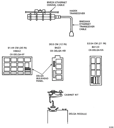
Figures 2-2 and 2··3 show how the module fits into the backplane and is connected to the bulkhead by the cabinet kit.
RE3415
Figure 2-2 Rear Panel, Bulkhead, Blanking Panel, and Modules
[image:38.613.130.514.322.657.2]INSTALLATION
91.44 CM (36 IN) H9642 CK·DELOA-KF
DDDD
DDD~
D[~D
c:::J
C:=l
c:::J
DELOA
BNE2X ETHERNET COAXIAL CABLE
30.5 CM (12 IN) BA23 CK- DELQA -KB
18
BULKHEAD
~B
PANEL
H400X TRANSCEIVER
BNE3XXX ETHERNET TRANSCEIVER CABLE
53.54 CM (21 IN) BA123 CK-DELOA-KA
DD
DD
DD
IJDD
DELOA MODULE
Figure 2-3 DELQA Cabinet Kits
1. Tum the system power off, and unplug the AC power line from the wall socket. 2. Remove the rear plastic cover by holding each end and pulling the cover towards you.
RE1683
3. Open the bulkhead panel (also called: the system I/O panel; or distribution panel) by loosening the two screws at the end opposite the hinge, and swinging it open.
4. Relocate modules and grant continuity cards as necessary to free the appropriate backplane slot(s) for the DELQA module(s).
[image:39.615.108.506.79.527.2]INSTALLATION
2.4.4 Cabinet Kit·
Figure 2-2 (Rear Panel, Bulkhead, Blanking Panel, and Modules) shows how the module is connected to the bulkhead by a cabinet kit and how the transceiver cable is attached to the other side of the bulkhead assembly. The center section of Figure 2-3 indicates the appropriate panel location for the DELQA in each cabinet type. 6. Remove the blanking panel from the appropriate location in the bulkhead panel by unscrewing the two
retaining screws. Save the two screws.
7. Insert the cabinet kit into the panel location, and secure the assembly using the two screws saved from the blanking panel.
8. Feed the cable from the cabinet kit to the module, and connect it to the module as indicated by the label THIS SIDE UP.
9. Connect a loopback connector to the bulkhead connector.
10. Turn the system power on and check for correct self-test LED indication (see Table 2-3).
If there is a problem in starting the host system, refer to the maintenance section of this guide. Table 2--3 Module LED Sequences
Normal Mode - Power-Up Sequence LEDt LED2 LED3 Definition
ON
ON
ON
ON
Executing internal logic self-testON
ON
Self-test executing external loopback testON
ON
ON Ready (to execute citizenship tests and/or nonnal functions) or module self-testDEQNA-Iock Mode -Power-Up Sequence
ON
ON
ON All LEDs come on and stay onIf an Ethernet boot is initiated in either Nonnal or DEQNA-Iock mode, or if software initiates a citizenship test, the following additional LED states are used.
LEDt LED2 LED3 Definition
ON ON
ON
Ready (to execute citizenship tests and/or nonnal functions) or module self-testON
ON
Executing citizenship testsON Internal loopback citizenship tests completed successfully
External loopback citizenship tests completed su.ccessfully
These sequences of LEDs should take less than 10 seconds. If the LEDs flash, this indicator error is discussed in Appendix D.
NOTE
LED states all ON, or all OFF at the end of the self-test indicate successful completion, depending on the boot mode.
INSTAlLLATION
11. Measure the power supply voltages for the system at the +5 V and + 12 V testpoints. They should be within the: tolerances defined in the host system manual.
12. Thm the system power off, and unplug the ac power line from the wall socket. 13. Disconnect the loopback connector.
14. Ensure that all cables are clear of panels and doors, and cannot be trapped or damaged by sharp edges. 15. Close the bulkhead panel and tighten the two screws at the end of the panel opposite the hinge.
2.S DIAGNOSTIC ACCEPTANCE TESTS This section desclribes customer-runnable diagnostics.
For fUTlther details of service-mode diagnostics, refer to Appendix B.
A MicroVAX II host and a MicroPDP-ll host have different diagnostic tests. For fUrither details, refer to Appendix B, and to the appropriate host system manual.
NOTE
Both MicroPDP-ll and MicroVAX II diagnostics distinguish DELQA modules from DEQNA modules in order to run tests specific to each type of module. MicroVAX I diagnostics do not support DELQA. The current Ethernet diagnostics are compatible with both DELQA and DEQNA. Early versions only support the DEQNA and cannot be used with the DELQA.
2.S.1 lnstallatiolR Tests on MicroPDP-ll Systems
To verify that the MicroPDP-ll system and the DELQA module are functioning correctly: 1. Switch on the system
2. BOlDt the MicroPDP-ll Customer Diagnostic media. Refer to your MicroPDP-ll System Manual for further information.
3. Type I at the main menu to allow the diagnostics to identify the new module, and add it to the configuration file.
NOTE
Look at the list of devices displayed, and make sure that the new module is included. If it is not included, repeat the installation sequence, and make sure that the module switches have been set correctly.
4. Type T at the main menu to run the system tests. These should complete without error; if an error occurs, callI DIGITAL Field Service.
INSTALLATION
2.5.2 Testing in Micro VAX II Systems 1. Switch on the system power.
2. Boot the MicroVAX Maintenance System media. Refer to your MicroVAX II System Manual for further information.
3. Type 2 at the main menu to show the system configuration and devices.
NOTE
Look at the list of devices displayed, and make sure that the new module is included. If it is not included, repeat the installation sequence, and make sure that the module switches have been set correctly.
4. Type 1 at the main menu to run the system tests. These should complete without error; if an error occurs, call DIGITAL Field Service.
2.6 CONNECTION TO ETHERNET
When diagnostics have shown an error-free system, connect the DELQA to an H4xxx transceiver or DELNI with a BNE3xxx cable.