ISSN: 1992-8645 www.jatit.org E-ISSN: 1817-3195
332
HARDWARE IMPLEMENTATION OF SATELLITE IMAGE
COMPRESSION FILTER USING
LIFTING BASED5/3 WAVELETS
1SENDAMARAI P., 2DR GIRIPRASAD M.N.,
1
Assistant Professor Nagarjuna College of Engineering and Technology, xxx, YYY
2
Professor & HOD ECE JNTU
E-mail: [email protected], [email protected]
ABSTRACT
Most of the satellite missions are of the remote sensing type used to image the places of interest on the Earth. With improving technology, the imaging payloads are become complex and as a result the data generated by these payloads is increasing exponentially. With limited on board resources and capabilities, it is important to process the data on board and compression of payload data is one of the important and crucial requirements. Lossless data compression is required as the raw data is of extreme importance and any loss of information cannot be afforded. This work presents a Le Gall 5/3 Wavelet based image compression implementation using Lifting technique in an FPGA for onboard payload data compression. The compression core achieves an operating frequency of 251MHz with a power consumption of 384mW. The image compression performance metrics are also evaluated and a PSNR of 29dB and compression ratio of 2.2 is achieved.
Keywords: Remote Sensing, image compression, Le Gall 5/3, lifting, PSNR
1. INTRODUCTION
Remote sensing is an important application of the satellite missions. The earth observation missions are increasing in complexity with the improving payloads used for imaging. The earth observation has seen dramatic changes from panchromatic images to multispectral to hyperspectral imaging over the past several years. The increasing complexity of payloads and improvements in the spatial resolution of the payloads, the volumes of payload data generated by these missions is also increasing. An appreciation of the fact can be obtained from the TOPSAT mission which provides PAN images at 2.5m GSD with 8000 pixels and MS images in three bands each at 5m GSD with around 2100 pixels. Each square PAN image and a square MS image acquisition generates 600Mbits of data and the satellite downlink is having a data rate of 11Mbps [Laycock et al. 2004]-[Cawley 2005] .
Most of the remote sensing missions are in the Low Earth Orbit and operate on a store and forward paradigm. As the LEO satellite has limited ground station availabil- ity, the payload data needs to be stored on board and then
transmitted at a later stage. The increased volumes of data hence puts stringent demands on the on board data storage and data transmission link to the ground. Due to constraints on the downlink bandwidth and satellite visibility period, it may need more than one satellite pass for complete data transmission [Dawood et al. 2001]. With limited on board storage and limited data transmission rates, it is imperative that the on board raw payload data be suitably compressed, stored and then transmitted to the ground.
ISSN: 1992-8645 www.jatit.org E-ISSN: 1817-3195
333 and FPGAs combine the flexibility of the software with the performance of hardware [Vestrum 2000]. Small satellite development is further enabled by the development of radiation hardened FPGAs [Dawood and Bergmann 2001], [DeHon 2000].
Image compression algorithms are of two types: lossy and lossless. In a lossless compression, the reconstructed image quality is the sameas the original image without any loss of information. The entropy measured by the lowest compression bit rate per pixel gives a theoretical boundary for lossless compression [Phamdo 2003]. On the other hand reconstruction from alossy compression leads to varying degree of information loss. Compression algorithms take advantage of several types of redundancies present in an imagelike the spatial redundancy, statistical redundancy and humanvision redundancy. Compression is achieved by removing one or all of these redundancies.
Many image compression techniques have been discussedin literature. Based on spatial decorrelation, the compression techniques can be classifiedinto prediction, DCT and DWT-based systems. Prediction based methods are DPCM [Jayant and Noll 1985] and adaptive DPCM. DWT based methods include the JPEG2000 [jpe 2000], SPIHT [Said et al. 1996]. Different DWT based compression systems like H-compress JPEG2000, ICER are used in the Mars exploration rovers. University of Idaho’sCAMBR is developing an ASIC for implementing CCSDS-IDC [Yeh et al. 2005]. An- other mission PLEIADES-HR will be using a DWT transform implemented in an ASIC [Thiebaut and Camarero 2012]. JPEG2000 standard is also used in IMS-1 [Srinivasan and Subramanian 2012]. GEZGIN another DSP card attainshigh throughput and maintains real timeoperation [Yu¨ ksel et al. 2005]. It implements the wavelet trans- form consisting of 5/3 coefficient integer filtering and signal decomposition and entropycoding and formatting.
Discrete wavelet transform have been used inthe image resolution enhancement of satellite images. Demirel et.al [Demirel and Anbarjafari 2011] applied interpolation of high frequency subbands obtained by discrete wavelet transform for image resolution enhancement. Image compression in case of Multispectral satellite images is achieved by removing spectral redundancy in Multispectral images through inter band spectral correlation [Saghri et al. 1995], [Benierbah and Khamadja 2006]. Hyperspectral satellite images require high
speed data processing because of higher number of spectral bands [Abousleman et al. 1995].
Comparison of lossless image comparison between traditional and lifting based wavelets is presented by Reddy et al [Reddy and Narayana 2012].
2. DISCRETEWAVELETTRANSFORM
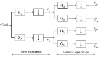
[image:2.612.324.511.334.424.2]Single stage of image decomposition into low frequency and high frequency components can be implemented using successive row and column transforms. In principle one level of DWT involves high pass and low pass filtering operations on row and column data separately. The filtering operation is followed by downsampling by a factor of 2. The downsampling operation removes the redundant information generated by filtering operation. A typical one level DWT is represented by Fig. 1.
Figure 1.1-D DWT Operation
In a two dimensional DWT, the signal isprocessed separately for rows and columns. The rows and column data represent the two dimensional image data. Representation of the same is shown in Fig 2. A 2-D DWT can be considered as a combination of two1-D DWT in the x, and ydirections. A 2-D DWT processor is designed by building1D DWT modules composed of high-pass and low-pass filters. These filters perform the convolution of filter coefficients and input data stream. After a one-level of 2-D discrete wavelet transform, the volume of image is decomposed into HH (High-High), HL (High-Low), LH (Low-High) and LL (Low-Low) signals as shown in Fig. 2.
[image:2.612.328.498.614.714.2]ISSN: 1992-8645 www.jatit.org E-ISSN: 1817-3195
334 The Le Gall’s 5/3 filter is an accepted standard filter for lossless data compression in the JPEG2000 standard and is widely used in image compression applications. Le Gall’s 5/3 wavelet filter is from the family of Cohen-Daubechies-Feauveau (CDF) wavelets where a B-spline is used as a primary generator polynomial for the CDFwavelets.All the generators and wavelets in this family are symmetric. For every positiveinteger A there exists a unique polynomial of degree 1 satisfying theidentity.
Table 1 CDF Wavelet Construction
Class A
LeGall’s 5/3 2 1+X 1 1+X
Daubechies
9/7 4 1 2X5/2
5/2
1-cX 1+(c+2)X+ ( 2 +5/2)
(1 − X/2)A QA (X ) + (X/2)A QA (2 − X ) = 1 (1)
This polynomial is used for the construction of CDF wavelets with QA (X ) factorizedas
QA (X ) = qprime (X )qdual (X ) (2)
Then, Equation 3 forms a biorthogonal pair of scaling sequences.
2 12 1 21⁄ "
2 #$%&' #1 &%$ &⁄ ' (3)
Substituting A = 2, gives the Le-Gall’s 5/3 filter as tabulated in Table I. Higher values of A (eg A=4) give lossy filters like the Daubechies 9/7.
Filters obtained from higher values of A result in a better compression ratio but at the same time the data loss is also higher. Le Gall’s 5/3 filter has low latency, pro- vides lesser image compression but is a Lossless filter. Most of the applications in remote sensing, the raw data (uncompressed data) is of high value and any loss of such data cannot be afforded. Hence, lossless compression is the solution for such ap- plications. Another distinction for image compression using discrete wavelet transform is the manner in which the filter is realized. The following section compares the two implementation methods for DWT.
3. CONVOLUTIONALVERSUSLIFTING METHOD
There are two main approaches of
implementing a 1-D DWT: the traditional convo- lutional based implementation [Mallat 1989] and the lifting based implementation [Daubechies and Sweldens 1998; Andra et al. 2002].
3.1. Convolutional 1D DWT
In convolution based 1D DWT, two analysis filters, low pass (h) and high pass (g) are used. The data stream x[n] is decomposed into the low frequency and the high fre- quency signal components. Downsampling operation follows the filtering and is done at the full sampling rate. In this method half of the calculated coefficients have to be discarded because of redundancy. An improvement over this made in the filter bank de- sign where the execution is faster using a polyphase matrix of filter bank instead of the conventional filtering-downsampling structure. Here, downsampling is done prior to filtering and hence the requirement to compute redundant coefficients does not arise. The polyphase components of the signal are filtered by the corresponding filter coeffi- cients parallely. The polyphase matrix is defined as:
() * +,- * ,. *
/- * /. * 0 (4)
The He (z) and Ho (z) denote the even and odd polyphase components of the low pass analysis filter and Ge (z) and Go (z) denote the even and odd polyphase components ofthe high pass analysis filter. With the polyphase matrix, the wavelet decomposition for the signal can be expressed as:
+12 *,2 * 0 (. * + - *
. * 0 (5)
Hardware Implementation of Satellite Image Compression Filter using Lifting based5/3 Wavelets :5
Figure 3. Lifting Based 1-D DWT Implementation
3.2. Lifting based 1-D DWT
ISSN: 1992-8645 www.jatit.org E-ISSN: 1817-3195
335 reconstruction filter pair (H, G), [Daubechies and Sweldens 1998] proved that it is possible to factor the polyphase matrix Eo (z) into lifting steps as:
( * +30 1 3⁄ 0 ∏ 60 9$ 1 7 *0 1 8+ 12 * 100
(6)
where K is a constant and m is the number of predict and update steps.
The forward lifting scheme is depicted in Fig. 3 and consists of the following steps.
(1) Decomposition: This step splits a signal (of even length) into two sets of coefficients, with even index indicated by evenj+1 and odd index indicated by oddj+1 . This is called the lazy wavelet transform.
(2) Prediction: As the even and odd coefficients are correlated, we can predict one from the other. More specifically, a prediction operator P is applied to even coefficients and the result is subtracted from the odd coefficients to get the detail signal
:;%$
:;%$ <::;%$ 2 =>=?;%$ (7)
(3)Update: An update operator U is applied to the odd coefficients and added to theeven coefficients to define ;%$
;%$ =>=?;%$ 7 :;%$ (8)
(4) Scaling: To ensure normalization, the approximation band ;%$ is scaled by a factor of K, and the detail band :;%$ by a factor of 1/K
The defining equations for the lifting method are given by Equations 9-11.
Table 2: Lifting Coefficient for Le-Gall 5/3 DWT
α β γ δ ζ Le-Gall 5/3
[An-gelopoulou et al. 2008]
-1/2 1/4 0 0 1
:$ @AB- C B- C 1 D B. C (9)
$ EA:$ :
F$
$ D B- C
: = γ( $ $%$)+ $
δ : :F$ $ (10)
HI ζ
HI 1/ζ : (11)
Equation 9 gives the predict (P1::$) and the update (U1: $) values for the first stage of lifting and equation 10 gives the predict (P2:: ) and update (U2: ) values for the second stage of lifting. Equation 11 is the scaling equation.
The beauty of the lifting transform is that the inverse DWT transform can be imple- mented by simply computing from right to left and switching the signs of the predict and update operators and scaling factors. The lifting based DWT implementation is prefered because of the lower computational complexity and the flexibility offered in terms of factorization and perfect reconstruction property.
A comparison of wavelet filter implementation using the convolutional and the lift- ing method [K. et al. 2005] shows that the lifting architecture results in smaller and faster hardware with lower energy consumption compared to the convolutional archi- tecture.
4. PROPOSEDARCHITECTUREFOR
IMAGECOMPRESSION
Le Gall’s 5/3 DWT filter implemented with lifting architecture is designed for image compression application for satellite images. The filter design has the following salient features.
(1) Lifting Based Implementation: The wavelet architectures for 5/3 filter is imple- mented using lifting scheme as against the convolutional implementation in [Amit and Joseph 2012].
(2) Scaled Coefficients: The filters design uses rounding and scaling of the coefficients.The advantage of this process is that the arithmetic units operate on integer sam- ples and thus reduces complexity of the hardware.
(3) Multiplier less Architecture: The filter architecture does not require any multipli- ers. All multiplication operations are implemented by shift operations. Multiplier less architecture improves the operating speed and reduces the complexity of im- plementation.
The basic lifting method is described by the predict, update and the scaling equations operating on even and odd samples of the input data stream. The lifting coefficients for the Le-Gall 5/3 are tabulated in Table II.
ISSN: 1992-8645 www.jatit.org E-ISSN: 1817-3195
[image:5.612.89.300.213.399.2]336 uses integer coefficients and hence the mathematical operations use inte- gers and are simpler to implement. Moreover the multiplication operations are imple- mented using shift operations. The equations for the lifting based Le Gall 5/3 DWT are given in Equation 12. The architecture uses the backbone of the basic lifting architec- ture for computing the Le-Gall 5/3 DWT.
Table 3: Synthesis Result
Parameter Value
Clock Speed 251.4 MHz Set up time 3.126 ns Hold time 3.253 ns Adders 4 Multipliers 0 Slice Registers 367 Slice LUTs 296
Power 5.23mW(dynamic) 378.99mW(static)
, 2A2? 1D A2? 1D K A2?D 2A2? 2DL
1 2A2?D A2?D 6M NA OF$D%PA O%$D%Q 8 (12)
where X[.] are the signal samples, HP and LP are the high frequency and low frequency outputs. The division by 2 and 4 are realized using shift operations.
The salient modifications proposed in the present architecture as compared to the conventional lifting architecture are as follows:
(1) Multiplication and division operations are decomposed into shifting operations which eliminates the requirement of multipliers.
(2) The architecture uses integer lifting coefficients. Hence the mathematical opera- tions use integer operands
5. IMPLEMENTATIONRESULTS
This section presents results for the performance of Le-Gall’s 5/3 filter in image com- pression of satellite imagery. The test images are obtained from high resolution satel- lite scene databse of Wuhan University [Zhang Xun ]. The design is
implemented in a XILINX XC5VLX30 FPGA hardware.
The performance of the image compression core is evaluated in terms of the compres- sion quality which is expressed in terms of the performance metrics like Mean Square Error, Peak Signal to Noise Ratio and Compression Ratio. The hardware implemen- tation is evaluated in terms of the utilization of the FPGA resources, the maximum operating frequency and the power consumption.
The quantitative results for the performance of the image compression DWT core are presented in this section along withthe image reconstruction performance and FPGA resource utilization.
5.1. Synthesis
The synthesis results of proposed architecture are tabulated in Table 3. The proposed design achieves a clock frequency of 251.4 MHz. As is obvious fromthe analytical equations, four addersare used. As the multiplication operations are carriedout by shift operations no dedicated multiplier is used. The totalpower consumption of the architecture is 384mW.
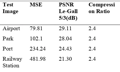
Table 4: Image Reconstruction Quality for the Proposed Le Gall 5/3 Image Compression
Test Image
MSE PSNR
Le-Gall 5/3(dB)
Compressi on Ratio
Airport 79.81 29.11 2.4 Park 102.1 28.04 2.4 Port 234.24 24.43 2.4 Railway
Station
481.98 21.30 2.4
5.2. Synthesis
The proposed compression architecture was evaluated for different test images for the image reconstruction quality studies. The image reconstruction was achieved by forward and inverse DWT transformation implemented in the same hardware. Results of the test are compiled in Table IV. The design achieves a good PSNR value for the test images in the range of 29dB for Le-Gall 5/3 filter.
[image:5.612.314.520.420.544.2]ISSN: 1992-8645 www.jatit.org E-ISSN: 1817-3195
337 (1) The work presents the results of the actual hardware implementation of the proposed architecture on XILINX XC5VLX30 FPGA Hence, the results present a more realistic and reliable performance.
(2) In this work, dedicated adders are used for all addition operations and no multipliers are used as all the multiplication and division operations are implemented using shift operations.
(3) This work achieves a clock frequency of 251MHz with an operating power consumption of 384mW.
6. CONCLUSION
An image compression core using the Le Gal’s 5/3 wavelets is presented for satellite image compression applications. The design of the compression core is in accordance with the wavelet based JPEG2000 standard. The design is implemented in a XILINX FPGA and the design results are presented. This work presents a detailed analysis of the compression performance of image compression including the hardware implementation result
REFRENCES:
[1] Information Technology- JPEG2000 Image COding System, Final Committee Draft Version.10. ISO/IEC JTC 1/ SC29/ WG1 N1646R (March 2000).
[2] Glen P Abousleman, Michael W Marcellin, and Bobby R Hunt. 1995. Compression of hyperspectral imagery using the 3-D DCT and hybrid DPCM/DCT. Geoscience and Remote Sensing, IEEE Transactions on 33,1 (1995), 26–34.
[3] Pande Amit and Zambreno Joseph. 2012. Poly-DWT: polymorphic wavelet hardware support for dynamic image compression. ACM Transactions on Embedded Computing Systems (TECS) 11, 1 (2012), 6.
[4] K. Andra, Chakrabarti Chaitali, and Acharya Tinku. 2002. A VLSI architecture for lifting-based forward and inverse wavelet transform. Signal Processing, IEEE Transactions on 50,4 (2002), 966–977.
[5] Maria E Angelopoulou, Konstantinos Masselos, Peter YK Cheung, and Yiannis Andreopoulos. 2008. Imple- mentation
and comparison of the 5/3 lifting 2D discrete wavelet transform computation schedules on FPGAs. Journal of Signal Processing Systems 51, 1 (2008), 3–21. [6] S Benierbah and M Khamadja. 2006.
Compression of colour images by inter-band compensated prediction. IEEE Proceedings-Vision, Image and Signal Processing 153, 2 (2006), 237–243. [7] Steve Cawley. 2005. TopSat: low cost
high-resolution imagery from space. Acta astronautica 56, 1 (2005),147–152. [8] Ingrid Daubechies and Wim Sweldens.
1998. Factoring wavelet transforms into lifting steps. Journal of Fourier analysis and applications 4, 3 (1998), 247–269. [9] A Dawood and N Bergmann. Singapore,
2001. Small satellites leveraged by unique computing technology. Proc. 3rd International Conference on Information, Communications and Signal Processing (ICICS-2001) (Singapore, 2001).
[10] AS Dawood, M Mikhalsky, A Cano, and W Boles. 2001. Spaceborne real time image processing system. In Proc. 3rd International Conference on Information, Communications & Signal Processing (ICICS-2001), Singapore.
[11] Andre´ DeHon. 2000. The density advantage of configurable computing. Computer 33, 4 (2000), 41–49.
[11] Hasan Demirel and Gholamreza Anbarjafari. 2011. Discrete wavelet transform-based satellite image resolution enhancement. Geoscience and Remote Sensing, IEEE Transactions on 49, 6 (2011), 1997–2004.
[12] Nuggehally S Jayant and Peter Noll. 1985. Digital coding of waveforms. Principles and applications to speech and video. (1985).
ISSN: 1992-8645 www.jatit.org E-ISSN: 1817-3195
338 [14] Catherine Lambert-Nebout and Gilles
Moury. 1999. A survey of on-board image compression for CNES space missions. In Geoscience and Remote Sensing Symposium, 1999. IGARSS’99 Proceedings. IEEE 1999 International, Vol. 4. IEEE, 2032–2034.
[15] J Laycock, V Van der Zel, N Morris, G Park, and W Levett. 2004. High resolution optical imaging with the low cost TopSat small satellite. In Proceedings of the 2004 International Astronautical Congress, IAC-04-IAA, Vol. 4. 4–8.
[16] Stephane G Mallat. 1989. A theory for multiresolution signal decomposition: the wavelet representation. Pattern Analysis and Machine Intelligence, IEEE Transactions on 11, 7 (1989), 674–693. [17] Stephane G Mallat. 1989. A theory for
multiresolution signal decomposition: the wavelet representation. Pattern Analysis and Machine Intelligence, IEEE Transactions on 11, 7 (1989), 674–693. [18] Nam Phamdo. 2003. Theory of
Data Compression. printed from http://www. Data-compression. Com/338heory. Html on Oct 10 (2003), 12.
[19] Dr B Eswara Reddy and K Venkata Narayana. 2012. A lossless image compression using traditional and lifting based wavelets. Signal & Image Processing: An International Journal (SIPIJ) 3, 2 (2012), 213–222.
[20] John A Saghri, Andrew G Tescher, and John T Reagan. 1995. Practical transform coding of multispectral imagery. Signal Processing Magazine, IEEE 12, 1 (1995), 32–43.
[21] Amir Said, William Pearlman, and others. 1996. A new, fast, and efficient image codec based on set par- titioning in hierarchical trees. Circuits and Systems for Video Technology, IEEE Transactions on 6, 3 (1996), 243–250. [22] R Srinivasan and JR et al Subramanian.
2012. TWSAT- MIssion Operations Plan. In Satellite Data Com- pression. Springer, 29–46.
[23] Carole Thiebaut and Roberto Camarero. 2012. CNES studies for on-board compression of high-resolution satellite images. In Satellite Data Compression. Springer, 29–46.
[24] G Vestrum. 2000. Design of a prototype system for image processing on reconfigurable computing technology. Master degree thesis, The Cooperative Research Center for Satellite Systems, School of Electrical and Electronic Systems Engineering, Queensland Univ. of Technology, Brisbane, Australia (2000).
[25] Pen-Shu Yeh, Philippe Armbruster, Aaron Kiely, Bart Masschelein, Gilles Moury, Christoph Schaefer, and Carole Thiebaut. 2005. The new CCSDS image compression recommendation. In Aerospace Conference, 2005 IEEE. IEEE, 4138–4145.
[26] Go¨ khan Yu¨ ksel, Onder Belce, and Hakan Urhan. 2005. BILSAT-1: First earth observation satellite of Turkey-Operations and lessons learned. In Recent Advances in Space Technologies, 2005. RAST 2005. Proceedings of 2nd International Conference on. IEEE, 846-851.