TRAJECTORY TRACKING BASED ON ARM’S LENGTH
VARIATION
1YASAMEEN KAMIL N., 2 D. HAZRY,3KHAIRUNIZAM WAN,4
ZURADZMAN M. RAZLAN,
1,3
School of Mechtronic Engineering, University Malaysia perlis (UniMAP)
2, 3, 4
Center of Excellence for Unmanned Aerial system (COEUAS) University Malaysiaperlis (UniMAP)
02600, Arau, perlis, Malaysia 1
Ministry of Science and Technology, Iraq, Baghdad E-mail: [email protected]
ABSTRACT
Recent growth in scientific technology, integrated actuators and data processing has made the improvement in Unmanned Aerial Vehicle (UAV), quadrotor; wholly possible. In this paper, a description of a novel controlling and modeling design of quadrotor based on the variation in the arm’s length with fixing the motors speed. This design is performed by utilizing a stepper motor mounted inside the fixed arm in order to increasing or decreasing the sliding arm which leads to increasing or decreasing the total arms length according to the required movement. A PD controller is used to stabilize the system performance in altitude, attitude angle and position, a new mathematical model consequent the proposed design. For the optimal selection of the arm’s length, a mathematical expression is designed. A MATLAB code is adopted for the simulation to study the stability of the quadrotor response according to the proposed design and its performance in the trajectory tracking.
Keywords:Arm’s length, PD controller, Quadrotor, Trajectory tracking, UAV
1. INTRODUCTION
The first concept of quadrotor has been launched to presence from the last decade. In 1907, First Quadrotor helicopter built by Breguet-Richet and reported to have aviation into trip [1]. Recently, the quadrotor considered as an interactive model that belong to the Unmanned Aerial Vehicle (UAV) and has many features. These features represented by its relatively small size, low cost, and uncomplicated mechanical design. This makes it elected to utilize in many applications, such as search and rescue, inspection and fire forest monitoring.
Quadrotor consists of four motors placed at the end of a cross frame. Each motor hold a propeller which responsible for creating thrust force that is lifted the quadrotor and providing the specific angle to the whole quadrotor frame during maneuverability. The balance of quadrotor is achieved by providing equal momentum around its axes when each pair in the same axis rotates in the same direction. Since, the motor pair (M2, M4) in y-axis rotates clockwise (C.W) while the motor pair (M1, M3) in the x-axis rotates counter-clockwise (C.C.W).Therefore, increasing or decreasing the all
motors speed produce relative vertical lift force. Varying the M2 and the M4 motors speed conversely generates roll rotation. The pitch rotation is achieved by varying the M1 and the M3 motors speed conversely. Yaw rotation accomplished by varying in the counter torque between the motors pairs. Since, M1and M2 decreasing their speed while M2 and M4 increasing their speed for (C. C. W) rotation and contrary to rotate (C. W)[2]. Regardless the four motors; quadrotor is under-actuated system.
controller. In [6], the position and altitude of
quadrotor are controlled by using PID controller in condition of a wind gust and conclude that the controller worked effectively under this condition. In [7] the PID based on feedback linearization combined with block control technique are used for controlling the position of quadrotor. This technique mathematically complex may have some fault in the mathematical model leads to a fault in the design, and the performance of the system is slow. The slide mode controller is used in [8] to tackle the motor faults and treat the disturbance and system uncertainties problem. However, there is a position error with the increasing of the magnitude of the faults, which effects on the motion of the quadrotor. In [9], the authors are used the backstepping controller for attitude, altitude and used PD controller for position control. Feedback linearization is used in [10] to control the attitude, position controller and from position controller can control the yaw angle freely.
In this paper, a new mathematical and controlling system design which capable of controlling the stability of quadrotor in attitude movements is proposed based on the variation of arms’ length. The proposed design depends on varying the length of arms instead of speed variation in motors. This design is implemented by using stepper motors placed inside each quadrotor’s arm in order to decrease or increase the length of the arm as a result of the control requirements. A PD controller used to stabilize the system performance. New mathematical model is derived due to this proposed design; a mathematical expression is designed for the proper selection of the arm’s length. Since the system is under actuated, the system divided into three subsystems which are altitude, attitude and position. The altitude and attitude subsystem can be controlled by one of the inputs while the position subsystem is dependently controlled by producing the desired attitude.
The proposed design exploits a new technique that depends on arm’s length variation. This technique tends to fix the motors speeds at the speed which ensure the hovering case when the quadrotor reached the desired z-position. According to hover case, the quadrotor motors thrust capable of lifting the quadrotor body. Then, the quadrotor movement is performed by varying the length of the quadrotor’s arm and fixing the motors
speed.
Consequently, the quadrotor is able to
move and make the manoeuvrability to
track the desired waypoint. As a result, a
variable torque is generated with respect to the
arms length variation of the quadrotor, instead of the torque generated by varying the speed of motors in the conventional design. This design is proposed to decrease the computational complexity, where no additional combination of other controllers with PD controller which is a linear controller used to control nonlinear system. On other hand, the proposed technique tends to increase the motors lifetime since the speed is fixed during the flying path and implicitly the energy consumption reduced. The stability of the quadrotor performance enhanced.
This paper is arranged as, section 2 presents quadrotor arm design, section 3 refers to quadrotor proposed design, section 4 regarding the dynamic model of quadrotor, section 5 presents controller design approach in altitude, attitude and position, section 6 refers to results and discussion, finally, section 7 refers to the conclusion
2. QUADROTOR ARM DESIGN
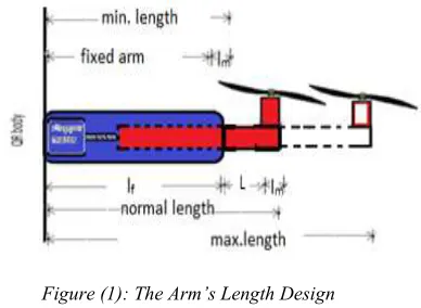
According to the proposed design each arm consists of two parts, the fixed part which represents that part which fixed with frame of the quadrotor and the stepper motor fixed inside it, the stepper motor shaft rotates with constant speed. The fixed arm is a hollow arm. The second part is the sliding arm which sliding inside the fixed arm and it connects to the stepper motor by the terminal which still slide inside the fixed arm, when the motor and propeller fixed on the second terminal that remains outside the fixed arm as shown in the figure (1) .
Figure (1): The Arm’s Length Design
[image:2.612.317.511.499.641.2]length of quadrotor and fixed the angular velocities
to control the movement of this vehicle in roll , pitch and yaw movement, in order to control the position(x, y) of the quadrotor which depends on pitch and roll angles respectively as assumption of;
• The angular velocity of each motor fixed to be constant.
• The arm’s lengths are varying according to the desired movement during the flight. • The thrust coefficients for all motors are
constant
• The quadrotor are supposed to be rigid body and symmetric
• The center of the mass and the origin of the body frame are coinciding.
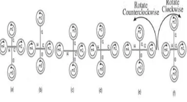
Firstly after the quadrotor reached the desired altitude (hover case) motors speeds are calibrated to be constant and altering the arms’ lengths of quadrotor and advance to the next movement. To accomplish pitch angle
θ
about y-axis, the length of arm (l1) must be decreased and the length of arm (l3) increases as shown in figure 2(a) and the other two arm’s length will be fixed at a constant length which is called a normal arm as shown in figure (1). In context, increasing and decreasing the arms length are performed in the proposed design according to equations (1) and (2) that the maximum length will be (l3) and minimum length will be (l1)(lf + lm + L) + ∆d * (lf + lm) = maximum length (1) (lf + lm + L) - ∆d * (lf + lm) = minimum length (2) Where lf and lm are the fixed arm and the diameter of the motor respectively,( L +lf + lm) represent the normal arm, L is specific length to ensure the permittivity in sliding arm movement, ∆d the rate of change in the sliding arm. While for the roll angle
φ
about the x-axis, can be accomplished by decreased the arms length (l2) and increased the arms length (l4) relatively and the same as pitch angle for the other two arm’s lengths as shown in figure 2(c). Finally, to accomplish yaw angle around the z-axis, this results from varying the counter torque between each pair of the propeller [1], that generate torque opposite the direction of propeller rotation. This can be done by increasing the arm length of motors pair (l2, l4) and decreasing the arms lengths of motors pair (l1, l3) in order to tilted the quadrotor in (C.C.W) direction as shown in figure 2(e) according to equations (1) and (2) the arms lengths (l2, l4) will be maximum length and the arms length (l1, l3) will be minimum length. Contrary, the quad rotor tilted in (C. W) byincreasing (l1, l3) and decreasing (l2, l4) as shown in figure 2(f).
Figure (2): Quadrotor’s Movements In Proposed Design
4. DYNAMIC MODEL OF THE QUADROTOR
Tow frames are utilized to represent the quadrotor motion which is body frame and earth frame [12]as shown in figure (3).
Figure (3): Architecture And Coordinates Of Quadrotor
A quadrotor consists of linear and angular position vectors related to the earth frame. Likewise, quadrotor consists of linear and angular velocity vectors related to the body frame. The position (x, y and z) and the orientation (
φ
,
θ
,
ψ
) of the quadrotor and the kinematics of the general 6-DOF of a rigid body[13] is defined as:=
•η
J
Θν
(3)Where
•
[image:3.612.323.505.138.238.2] [image:3.612.322.527.339.494.2]
=
× × Θτ
3 3 3 30
0
E
J
(4)Where E ,
τ
are the transformation and rotation matrices and the term0
3×3representing a3
×
3
zero matrix, E defined according to[15]. E=(
5
)
−
+
−
−
+
−
φ θ θ φ θ ψ θ φ ψ φ ψ φ ψ θ φ ψ θ ψ φ θ ψ φ ψ φ ψ θ φ ψ θc
c
c
s
s
s
s
c
c
s
c
c
s
s
s
s
c
c
c
s
s
s
s
c
c
s
s
c
c
Where c (.) represents cos (.) and s (.) represents sin (.). The dynamic model of the quadrotor based on Newton- Euler formula with respect to body frame will be expressed as in[7]. × + = × + = • • • ω ω ω ω I I T mv v m F (6)Where m and I= diag (Ix, Iy, Iz) are the mass of quadrotor body and moment of inertia matrix respectively, F,T are the total aerodynamic force and moment effected on quadrotor motion which is mentioned in [7]. According to the proposed design since fixing the angular velocity, the thrust and drag forces are equaled for all motors (f1=f2=f3=f4=fi) and (D1=D2=D3=D4=Di) respectively. Varying the lengths of the arms generate variable torque around the axis that achieved the required rotation. Then, the quadrotor tilted toward the least torque in pitch and roll attitudes angles, yaw attitude angle tilted toward the largest torque as illustrated in section (3) The total torque affected on the quadrotor rotation in [17] expressed in the proposed design as:
∑
∑
∑
∑
= = = + = − + − + − + − + − + − = 4 1 1 3 4 1 2 4 4 1 1 4 1 } { ) 1 ( )} ( { )} ( { ) ( . ) ( ) 1 ( ) 1 ( i z i i i y m m i i x m m i i i i i i i i total l D l l f l l f yx D h xy R z Q T (7)Where fi and Di represent the lift and drag forces respectively, acting on the quadrotor movements and defines in [4] as: 2 2
ω
ρ
r
c
f
i=
TΑ
(8)2 2
ω
ρ
r
c
D
i=
dΑ
(9)Where A represents the blade area,
ρ
represents the air density, r represents the radius of blade, ω represents the angular velocity of the propeller, andc
Τandc
d represent aerodynamic coefficientsQ
and R represent the torque from each motor and the rolling moment which are expressed in[17] as; Qi cd r r 2 2ω ρΑ = (10)R = CRρΑr2ω2r (11)
h represents the distance between propeller center and gravity center of quadrotor, lmi represents the arm’s length from the pivot center t the related motor as shown in fig (3). The quadrotor dynamic model equations expressed in earth frame as in [1]: − + − = − + − = − + − = − − = − + − = − + = • • • • • • • • • • • • • • • • • • • • • • • • ψ θ φ ψ θ ψ φ θ φ ψ θ φ θ φ ψ θ φ ψ φ ψ θ φ ψ φ 6 4 5 3 4 2 3 1 2 1 1 1 ) ( ) ( ) ( ) cos (cos ) cos sin cos cos sin ( ) cos sin cos sin (sin k u I I I k u I I I k u I I I z k mg u z m y k u y m x k u x m y x z x z y z y x (12) Where ki’s represent the frictions aerodynamic coefficients, and u1, u2, u3 and u4 represent the input to the system which defined as; u1= f1+f2+f3+f4 (13)
u2= fi (- l2+l4) (14)
u3= fi (- l1+l3) (15)
u4=Di (- l1 – l3 + l2 + l4) (16)
Whereas the input to the system in conventional design are defined in[16] as u1=f1+f2+f3+f4 u2= l. (-f2 + f4) (17)
u3 = l. (-f1 + f3)
u4 = -Q1 + Q2 - Q3 + Q4
Where b=
c
Tρ
Α
r
2which is the thrust coefficient, d=c
dρ
Α
r
2which is the drag coefficient.In this paper, a PD control system is used for
quadrotor stabilization performance. PD controller represents an effective linear controller which used to stabilize the nonlinear system [18]. This controller used to control the altitude, attitude and position of quadrotor. Figure (4) shows the block diagram of the control approach for quad rotor stabilization. In order to full control the quadrotor and track the trajectory, the vehicle follows three controllers in operation. Where, Take-off and landing to the desired point which is implemented using the altitude controller, the desired position (x, y) implemented using the position controller depending on the attitude controller which maintains the quadrotor in 3-D orientation. The output from the position controller is the desired angle to the attitude controller which facilitates to the position controller reaches its desired position in x and y axes without deviation
5.1 Altitude Controller Design
For quadrotor take-off case from the ground to the desired height, the altitude controller is employed. This mean must work on the z-axis equation of quadrotor and don’t deal with other axes equation. From equation (12) select z axis equation and used PD controller as following:
Figure (4): Block Diagram Of Quadrotor Full
Control
mg
u
z
m
=
−
• •
)
cos
(cos
1
θ
φ
(18)Since ϕ=Ө=0 for hovering and take-off condition [6] the error signal (
e
z) is the difference between the desired altitude (zd) and measured altitude (z)[19] as shown in equation (19)z
e
=z
d−
z
(19)The PD controller equation is shown below.
•
+
=
k
pe
zk
de
zu
1 (20)Where kp,and kd are the proportional and derivative
gains respectively. Then the closed loop system after adding the PD controller to the equation (18) will be as in equation (21).
mg
e
k
e
k
z
m
=
p z+
d z−
• ••
(21)
5.2 Attitude Controller Design
For this system a PD controller is used to stabilized the attitude angles (roll, pitch and yaw) which is directly controlled by (u2, u3 and u4) respectively. These represent the last three equations of equation (12) and after neglecting the gyroscopic effect as in [13].
−
=
−
=
−
=
• •
•
• •
•
• •
•
ψ
ψ
θ
θ
φ
φ
6 4
5 3
4 2
k
u
I
k
u
I
k
u
I
z y x
(22)
The error signals (eϕ, eӨ and e ) will the
difference between the desired angels (ϕd, Өd
and d ) and the measured angels(ϕ, Ө and ) as in
equation below:
−
=
−
=
−
=
ψ
ψ
θ
θ
φ
φ
ψ θ φ
d d d
e
e
e
(23)
The equation of PD controller for roll attitude will be as in equation (24).
•
+
=
φ φφ
k
e
k
e
u
p d (24)In the same manner, the other attitude angles PD controller can be derived. The closed loop system after addition the effect of PD controller in equation (24) to equation (22) will be as in equation (25).
φ
φ
u
I
u
x
2
=
• •A PD controller is used to control the horizontal
motion. This motions accomplished by pitching or rolling the quadrotor by generates the pitch and roll angle from this controller which it will be the input to the attitude controller. The saturation function is used to control the boundary of these angles. Then, from equations (26) and (27) the desired
acceleration (
• • • •
y
x
,
) is calculated as in [9].• •
•
+
=
p x d xd
k
e
k
e
x
(26)• •
•
+
=
p y d yd
k
e
k
e
y
(27)Where kp and kd are positive and constant
proportional and derivative gains respectively. ex
and ey are the error signal which expressed as in
equation (28) and (29).
x
x
e
x=
d−
(28)y y
ey = d − (29)
Where
x
d,
y
dthe desired position and x, y are the measured position, by applied equations (26) and (27) into equation (12) for x and y position will obtain=
• •
d
x
) cos sin cos sin
(sin
1 φ ψ + φ θ ψ
−
m
u (30)
) sin sin cos cos
(sin
1 φ ψ − φ θ ψ
=
• •
m u yd
(31)
As assumption of hover case in position controller =0 and Ө and ϕ are small angles approximation. Then can calculate the desired pitch and roll angles from equations (30) and (31) respectively.
) ( sin
) ( sin
1 1
1 1
• • −
• • −
= =
d d
d d
y m u
x m u
φ
θ (32)
The Өd and ϕd must be limited to a specific
range, by using saturation function which is expressed below as.
−
<
−
≤
≤
−
>
=
d d
d d
d d
d
sat
θ
θ
θ
θ
θ
θ
θ
θ
θ
θ
θ
)
(
(33)6. RESULTS AND DISSECTION
In order to realize the efficiency of the proposed design adopted. MATLAB code simulation is performed. This section present the result of the altitude, attitude, position controller and trajectory tracking and the system parameter used as in table (1). As mentioned in section (2) and section (3) the arm’s length designed as the fixed arm will be equal to 17.5cm and the maximum total arm’s length will be equal to 30 cm and the minimum arm’s length will be equal to 20 cm.
Table 1: The System Parameters
mass 2 kg Iz 2.5 Ns 2
/rad
Arm length
As in table 2 b 3.31*10-5
gravity 9.8 m/s2 d 7.5*10-5
Ix 1.25 Ns2/rad k1= k2=k3 0.010 Ns/m
Iy 1.25Ns2/rad k4=k5=k6 0.12 Ns/m
Table 2: Arm’s Length Variation According To Section 3
f
l
(cm)m
l
(cm)L
(cm) ∆d
Max. length(cm)
Min.
length(cm)
17.5 2.5 5 0.25 30 20
Figure (5): Desired Waypoint For X, Y, Z
Figure (6):Quadrotor Trajectory Tracking
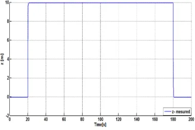
The measured altitude is shown in figure (7) while the yaw angle shown in figure (8)which illustrate that the proposed design works well with the yaw angle with no oscillation and reach the desired with the time equal to 18 sec . Figure (9) and figure (10) show the x-position and the pitch angle as the control input to the x direction which at 60 sec x-position move to point 5m and the pitch angle changes its state from 0 rad to the desired pitch angle which is -0.35 rad. There is little difference in the magnitude between the measured angle and the desired angle as shown in figure (10). After the x-position reaches the desired the pitch angle converges to zero and advanced to next step.
Figure (7): The Measured Altitude
Figure (8):The measured Yaw angle
Figure (9): The measured X- position
Figure (10): The Measured And Desired Pitch angle
[image:7.612.90.525.62.510.2] [image:7.612.96.289.253.382.2] [image:7.612.326.507.552.685.2] [image:7.612.97.287.574.701.2]Figure (12): The Measured And Desired Roll Angle
Figure (11) and figure (12) show the y-position and its control input, the roll angle, which at 100 sec quadrotor moves to 5m in y-position and the roll angle responses to this change and followed the desired roll angle. Then, converge to zero in order to advance to the next point. From these results, the proposed design shows the stability in response and follow the desired accurately with good performance.
7. C ONCLUSION
In this paper, a new controlling method based on varying the arm’s length is applied successfully to control the quadrotor movement. This method implemented based on PD controller for altitude, attitude and position controller due to this approach a mathematical model is developed and derived using Newton- Euler method. A mathematical expression is designed to identify the amount of increment and the decrement in arms’ lengths. The simulation results show a perfect performance of the proposed design in tracking the desired path. The proposed design with PD controller proves the capability for controlling the orientation angles and develops the stability of autonomous vehicle.
REFRENCES:
[1] S. BOUABDALLAH, P. MURRIERI, AND R. SIEGWART, "DESIGN AND CONTROL OF AN
INDOOR MICRO QUADROTOR," IN ROBOTICS
AND AUTOMATION, 2004. PROCEEDINGS.
ICRA'04. 2004 IEEE INTERNATIONAL
CONFERENCE ON,2004, PP.4393-4398.
[2] A. R. Patel, M. Patel, and D. R. Vyas, "Modeling and Analysis of Quadrotor Using Sliding Mode Control," in System Theory (SSST), 2012 44th Southeastern Symposium on, 2012, pp. 111-114.
[3] S. Bouabdallah and R. Siegwart, "Full Control of a Quadrotor," in Intelligent robots and systems, 2007. IROS 2007. IEEE/RSJ international conference on, 2007, pp. 153-158.
[4] A. Azzam and X. Wang, "Quad Rotor Arial robot Dynamic Modeling and Configuration Stabilization," in Informatics in Control, Automation and Robotics (CAR), 2010 2nd International Asia Conference on, 2010, pp. 438-444.
[5] A. L. Salih, M. Moghavvemi, H. A. Mohamed, and K. S. Gaeid, "Modelling and PID Controller Design for a Quadrotor Unmanned Air Vehicle," in Automation Quality and Testing Robotics (AQTR), 2010 IEEE International Conference on, 2010, pp. 1-5.
[6] M. K. Joyo, D. Hazry, S. F. Ahmed, M. H. Tanveer, F. A. Warsi, and A. Hussain, "Altitude and Horizontal Motion Control of Quadrotor UAV in the Presence of Air Turbulence." [7] H. K. Kim, T. T. Nguyen, S. J. Oh, and S. B.
Kim, "Position Control of a Small Scale Quadrotor Using Block Feedback Linearization Control," in AETA 2013: Recent Advances in Electrical Engineering and Related Sciences, ed: Springer, 2014, pp. 525-534.
[8] A.-R. Merheb, H. Noura, and F. Bateman, "Active Fault tolerant Control of Quadrotor UAV Using Sliding Mode Control," in Unmanned Aircraft Systems (ICUAS), 2014 International Conference on, 2014, pp. 156-166. [9] A. Nagaty, S. Saeedi, C. Thibault, M. Seto, and H. Li, "Control and Navigation Framework for Quadrotor Helicopters," Journal of Intelligent & Robotic Systems, vol. 70, pp. 1-12, 2013. [10] S.-h. Lee, S. H. Kang, and Y. Kim, "Trajectory
Tracking Control of Quadrotor UAV," in Control, Automation and Systems (ICCAS), 2011 11th International Conference on, 2011, pp. 281-285.
[11] A. L. Salih, M. Moghavvemi, H. A. Mohamed, and K. S. Gaeid, "Flight PID controller design for a UAV quadrotor," Scientific Research and Essays, vol. 5, pp. 3660-3667, 2010.
[12] S. Bouabdallah, A. Noth, and R. Siegwart, "PID vs LQ Control Techniques Applied to an Indoor Micro Quadrotor," in Intelligent Robots and Systems, 2004.(IROS 2004). Proceedings. 2004 IEEE/RSJ International Conference on, 2004, pp. 2451-2456.
[13] Y. Ming and X. Yunqing, "Design of Nonlinear Aero Controller and Simulation for Quadrotor Unmanned Aerial Vehicles," in Software Engineering (WCSE), 2013 Fourth World Congress on, 2013, pp. 283-287.
Takeoff/Landing And Altitude Stabilization Of
Quad-rotor," Journal of Applied Sciences Research, vol. 9, pp. 3316-3327, 2013.
[15] M. H. Tanveer, D. Hazry, S. Faiz, M. Kamran, and F. A. Warsi, "Design of Overall Stabilized Controller for Quad-rotor," Kärntner Botanikzentrum, 2013.
[16] R. Cavalcante Sa, A. L. C. De Araujo, A. T. Varela, and D. A. Barreto, "Construction and PID Control for Stability of an Unmanned Aerial Vehicle of the Type Quadrotor," in Robotics Symposium and Competition (LARS/LARC), 2013 Latin American, 2013, pp. 95-99.
[17] A. A. Mian and W. Daobo, "Modeling and Backstepping-Based Nonlinear Control Strategy for a 6 DOF Quadrotor Helicopter," Chinese Journal of Aeronautics, vol. 21, pp. 261-268, 2008.
[18] I. Gonzalez, S. Salazar, H. Romero, R. Lozano, and J. Torres, "Attitude Control of a Quad-rotor Using Speed Sensing in Brushless DC Motors," in Electrical Engineering Computing Science and Automatic Control (CCE), 2011 8th International Conference on, 2011, pp. 1-6. [19] A. A. Mian, M. I. Ahmad, and D. Wang,
"Backstepping Based Nonlinear Flight Control Strategy for 6 DOF Aerial Robot," in Smart Manufacturing Application, 2008. ICSMA 2008. International Conference on, 2008, pp. 146-151.