EAr
ELECTRONIC ASSOCIATES. INC.
CONTENTS
SECTION 1 EAI 640 SYSTEM
Introduction . . . • . . . 1-1 640 System Summary ... 1-1 Characteristics of the Basic 640 Computer ..• 1-2 EAI 640 Central Processor .•....•...•...••.. 1-7 Arithmetic Section. ... ... .•.... .•.. 1-7 Control Section. . . • • . . . • . . • • • . . • . . . 1-9 Memory Section ..•...•.. 1-10 EAI 640 Address Structure .• • • • . . • . . . • . . . 1-11 Storage Word ..•...•.•.•.••...••.••.••.... 1-11 Storage Addressing .•..•••.•..•••.••....•.. 1-11 Addressing Concept of the 640 Computer ..•.. 1-12 EAI 640 Interrupt System ... 1-15 General Description .•.•.•...••...•.•.. 1-15 Master Interrupt ....•...•.•••.•...•... 1-17 Program Status Word (K Register) ....•••... 1-17 Prese+vation of Registers During Interrupts .• 1-17 Priority . • . • . . • . . . • . • . . . • . . . . • . . . • 1-17 InternalInterrupts .••••••••••..••...•... 1-18 External Interrupts • • • •• •• • . . . • . • • . . • . • • . • 1-18 Absolute Priority .•. • • . • • • • • • • . • . • . • • . . . • . 1-19 Pointers... 1-19 Description of Interrupts ••••.••...•.••..••. 1-19 EAI 640 Memory Protect System ••.•....•...•...• 1-21 EAI 640 Input/Output System ••.••••••.••.••••.••. 1-23 Introduction •..•...•...•.•.... 1-23 Single Word Mode Input/Output •..• . • . • . . . 1-23 Record Mode Input/Output •.•••....•.••..••• 1-24 Direct Memory Access Channel (DMAC) ... 1-25 EAI 640 Instruction Repertoire ....•.•..•... 1-29
SECTION 2 EAI 640 PERIPHERALS DESCRIPTION
Introduction •...•...•.•••...•••...•... 2-1 640/960 Floating Point Processor ...•.. 2-1 Data Format. • . . . • • • • • • . • • • . • . . . • . . . 2-2 Commands a.nd Timing... ...•• 2-2 Control Word Format... 2-3 Software •••.•..•.•.•.••..•••...•.•..•.. 2-3 Physical Requirements... ...•. ... 2-3 640/260 Data Disc Storage System. .. .. .. ... .. 2-5 Teletype Writer Station .. . . 2-7 Paper Tape Station . . .... .... .. ... . . 2-9 640/520 Card Reader . . . 2-11 640/610 Line Printer . . . 2 -13 640/720 Magnetic Tape Controller
and Transport. . . .. .. . . .. . . .. . . 2-15 EAI 640 System Configurator ..•...••...•..•.•.... 2-17
SECTION 3 EAI 640 SYSTEM SOFTWARE
section
EAI 640 SYSTEM
INTRODUCTION
The EAI 640 Digital Computing System provides the user with an outstanding,
general purpose, computing capability for handling a wide range of scientific
ap-plications. It includes flexible input/output and interrupt features that make it
particularly useful in combined hybrid and special systems for simulation, hybrid
computation, on-line monitoring/control and other uses.
The EAI 640 is a parallel, binary computer that operates with a fixed length 16
bit instruction and data word. It has a protected core memory with a maximum
storage capacity of 32,768 words. Each word in memory has a protect bit and
violations are immediately recognized through interrupt procedures in the
com-puter.
The EAI 640 offers an extensive list of instructions, multi-level interrupt
capa-bility and high speed input/output operations for communication with up to 64
peripheral devices.
The EAI 640 System is of modular design. Memory can be expanded from the
basic 8K to 16 or 32 K. The basic EAI 640 contains interfaces for connection
to interval timers. A Direct Memory Access Channel can be added to allow high
speed input/output interleaved with computation on a cycle stealing basis.
Ad-vanced integrated circuitry makes the EAI 640 a member of the third generation
computer family combining reliability with high speed logic.
640 SYSTEM SUMMARY
Stored program, general purpose digital computer
Monolithic integrated circuitry
64 Instructions including:
Add/Subtract
Multiple precision hardware features for Add/Subtract
Multiply/Divide
Square Root
Logical
Inter -Register Exchanges
Fixed word length of 16 data or instruction bits
16-bit Storage Word - plus a memory Protect bit
Magnetic Core Storage
1. 65 Microseconds cycle time
Basic Size 8, 192 words
Expandable to 16,384 Or 32,768 words
Multi-level Indirect Addressing
Two's Complement Binary Arithmetic
Index Registers
One Hardware register
An indefinite number of memory words can be used as index
coun-ters.
7 Internal Interrupts and 64 External Interrupts
Input/Output
Single Word Mode
Record Mode
Direct Memory Access Channel (Optional)
Four Interval Timer Interfaces
CHARACTERISTICS OF THE BASIC 640 COMPUTER
Arithmetic Operations
The EAI 640 performs all arithmetic operations using two's complement binary
arithmetic.
ADD/SUBTRACT OPERATIONS
Addition and Subtraction can be performed in either single or multiple
preciSion format. When the multiple precision bit is on, the
carry/bor-row bit automatically provides a carry or a borcarry/bor-row when operating on the
next higher precision word. When a multiple precision bit is off, single
precision arithmetic is performed.
MULTIPLY/DIVIDE OPERATIONS
A Multiplicand contained in the Accumulator is multiplied by the
multi-plier as speCified by the effective address. The resulting product is
double length and is contained in the Accumulator and the Accumulator
Accumulator, the least significant portion is in the Q register. In the
Divide operation, the dividend contained in the Accumulator and the
Ac-cumulator Extension is divided by the divisor contained in the memory
location specified by the effective address. After division, the quotient
with sign is contained in the Accumulator and the remainder is in the
Ac-cumulator Extension.
Basic Computer
The basic EAI 640 Computer System is available with 8,192 words of core
stor-age. The basic 640 Computer with 8K of memory and an upright console is the
640/008 and the same computer with a desk mounted operator console is the 640/
018.
MEMORY EXPANSIONS
The 640/008 and 640/018 can be expanded to 16K in the field with the 640/
208 Memory Conversion Unit. In addition, the 640/216 allows field
mod-ification of a 16K computer system to the full 32K version.
Memory Data and Address
A 16-bit Memory Data Register (M) holds data written into, or read out of core
memory. The Memory Address Register (S) holds the address specifying where
a word is to be read from or written into core storage.
Indexing Operations
HARDWARE INDEX REGISTER
The EAI 640 has an Index Register (X)for high speed address modification
without increasing instruction execution time o The X Register includes
15 address bits and a post-index indirect bit. This post-index indirect
bit specifies whether the calculated address is to be the effective address
or will result in a further indirect address o The Index Register can be
transferred directly to or from memory without affecting the Accumulator.
Increment or decrement of the Index Register followed by a Skip is
MEMORY COUNTERS
The EAI 640 allows counting operations with the content of any memory
location. With one instruction, a memory location can be incremented
and tested. This capability allows the programmer an unlimited number
of counters which can be serviced and tested with one instruction each.
Memory Protection
Each core memory location in. the EAI 640 Computer has a protect bit. This bit
can be set or reset under program control only if the protect switch on the
con-sole is in the ON position. Violations of the protect system generate an
inter-rupt and the contents of the memory location involved in the violation are not
changed.
1/0
SystemThe EAI 640 Computer can handle input and output in two modes. The single word
mode transfers one word at a time into or out of the Accumulator. In the Record
Mode, consecutive memory locations are automatically accessed for input or
out-put. Block transfers can be made easily by specifying a starting and the final
word address. After completion of the record transfer, a terminating address
is available which can be examined against the last word address which has been
specified. The extensive interrupt capabilities of the 640 allows I/O operations
to proceed without constant need for status testing of the peripheral devices.
Bootstrap Operation
After clearing the computer (setting the hardware registers and me mory to zero),
the Execute Run switch will cause a bootstrap program to be read from the
tele-type paper tape reader which, after loading itself, will turn control over to the
program which was loaded. This hardware feature allows the user to get off
Direct Memory Access Channel
(640/310)The basic EAI 640 Computer can expand its input/output capabilities through the
addition of an optional Direct Memory Access Channel. Direct memory access
operates on a cycle stealing basis which allows computation to proceed
EAI 640 CENTRAL PROCESSOR
The EAI 640 Computer performs all calculations and processes data in a parallel,
binary mode through the execution of individual instructions. Both
in-structions and data are stored in the magnetic core storage of the 640 Computer
system. The 640 Computer is divided functionally into three sections, arithme-·
tic, control, and memory.
ARITHMETIC SECTION
The Arithmetic Section of the EAI 640 Computer performs the arithmetic and
logi-cal operations necessary for execution of instructions. This section has several
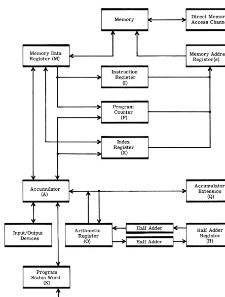
operational registers. Figure 1 shows a generalized logic block diagram of the
640 Computer. It should be emphasized that not all registers shown on this
dia-gram are available to the prodia-grammer for direct operations. For example, the
Half-Add Register (H) is necessary for proper operation of the Arithmetic
Sec-tion, but cannot be directly manipulated by any instruction in the repertoire of the
640 Computer.
Accumulator (A Register):
The Accumulator is a 16-bit register used in arithmetic, logical and
input/output operations.
Accumulator Extension
(Q
Register):The Accumulator Extension is a 16-bit register used in double shifting
operations,' multiply, divide, square root and record mode input/output
operations.
Arithmetic Register (0 Register):
The Arithmetic Register is a 16-bit register used in the execution of
cer-tain instructions. It is not available to the programmer, except for
con-sole display and manipulation.
Half-Adder (H Register):
This 16-bit register is used in the execution of certain instructions but is
Memory Data Register (M)
Accumulator (A)
J" J
,if
Input/Output Devices
Program Status Word
(K)
Interrupts
Memory III"",,~----,~ -* ... Access Channel Direct Memory
' -_ _ _ _ _ _ ~ Memory Address
....
..
Instruction Register(I)
:. Program Counter ... (P)
'1-_---.... Index
~,
Register ... (X)
'
....
_---,Ir
Arithmetic
~
Half Adder Register(0)
--+I
Half Adder..
[image:11.638.81.525.95.682.2]l+--~
Figure 1. Block Diagram - EAI 640 Computer
Register(s)
Accumulator Extension
(Q)
Half Adder Register
Program Counter (P Register):
The Program Counter is a 15 -bit register containing the memory address
of the next instruction to be executed. After the instruction to be
exe-cuted is placed in the Instruction Register the P register is incremented
by one. The P register may be further changed by the instruction being
executed. The P register has 15 bits and can generate addresses from
00000 to 32, 767 which is the maximum memory capacity of the 640
Com-puter.
Index Register (X Register):
This 16-bit register is used in indexing operations. The index value can
be positive or negative in two's complement form and contains an Indirect
Addressing bit position.
Instruction Register (I Register):
The Instruction Register is a 17 -bit register which contains the
instruc-tion currently being executed and its program protect bit. The register
is not directly available to the programmer, except for console display
and manipulation.
Program Status Word (K Register):
The Program Status Word is a 16-bit register which contains the enable/
disable bits for each interrupt level, the condition codes, the multiple
precision and carry/borrow bits.
CONTROL SECTION
The control section of the EAI 640 Computer directs the operations required to execute instructions and establishes the timing relationships needed to perform
these operations in their proper sequence. It also controls memory usage,
in-terrupt processing, program protection, and input/output operations. The
con-trol section acquires an instruction from storage, interprets it, and sends the
necessary commands to other sections. The Program Counter (P) provides
pro-gram continuity by generating in sequence the storage addresses which contain
MEMORY SECTION
The Memory Section of the EAI 640 Computer consists of two registers and the
Storage Modules. The basic computer may have 8,192 words of high-speed,
ran-dom access, 2-1/2 D, magnetic core storage which can be expanded to 16,384
or 32,768 words. Storage cycle time is 1.65 microseconds which is defined as
the shortest possible time between successive read/write operations in core
memory.
Memory Data Register (M Register):
The Memory Data Register is a 17 -bit register from which information is
written into memory and to which information is read from memory (16
information bits and a protect bit).
Memory Address Register (S Register):
The Memory Address Register is a 15 -bit register which contains the
ad-dress in memory from which information is to be read or into which
EAI 640 ADDRESS STRUCTURE
STORAGE WORD
A Storage Word may be a 16-bit instruction, a 16-bit operand, one-half of a
31-bit operand (divide or square root) or a 16-31-bit portion of a multiple precision
operand. A Program Protect bit is appended to each l6-bit storage word, thus
a storage word is 17 bits long. H the Protect Bit is a "1", it indicates that the
word is part of a protected program.
STORAGE ADDRESSING
The location of each word in storage is identified by an assigned number
(ad-dress). An address consistsof15 bits. Instructions, which reference core
mem-ory, have three fields: 4-bit Operation Code, 3-bit Address Mode (E field), and
a 9-bit Displacement Field. As a matter of convenience, an instruction may be
expressed as a six digit octal number, where the first digit may only be a 0 or 1.
The first two octal digits will be the operation code, the third will be the E field
and the last three digits the displacement address.
The terms used to describe memory addressing methods are:
EA - effective address: the destination location containing the data which
is to be used for computation.
IA - indirect address: a location containing an address which indicates where the intended operand may be found. Multi-level indirect
address-ing is defined as a series of memory locations containaddress-ing indirect
ad-dresses which are referenced in sequence by the computer.
D Field - displacement: bits 7 to 15 of a memory reference instruction.
Treated as either:
(a) a 9-bit positive number in the range of 0 to 511;
(b) an 8-bit signed number in the range of -256 to +255.
E Field: bits 4, 5 and 6 of a memory reference instruction.
Bit 4 - indicates indirect addressing will take place (I).
Bit 5 - indicates index register addressing will take place (X).
Bit 6 - indicates relative-to-program-counter addressing will take place
(P).
I: Indirect addressing will take place followed (optionally) by
In-dexing and further Indirect Addressing.
X: the contents of the index register. The most Significant bit (zero)
determines whether the resulting address is the effective
ad-dress or is to be interpreted as a further indirect adad-dress. If
bit 0 of the index register is "0" the resulting address is the
effective address.
P: the content of the program counter register which is the
loca-tion of the current instrucloca-tion.
ADDRESSING CONCEPT OF THE 640 COMPUTER
To understand the addressing concept of this computer, it is necessary to
con-sider the memory of the computer in relation to the bits available in an
instruc-tion for addressing. The Displacement field, when treated as a 9-bit positive
number, yields a range of 0 to 511 addresses. Therefore, the" Zone Zero" area
from location 00000 to 00777 (octal) becomes available to the programmer
di-rectly.
The method of addressing these low core locations is commonly referred to as
Absolute Addressing. It often is convenient to store counters or to provide
tem-porary storage for intermediate results in this low core area because of the
con-venience of addressing through the displacement portion of the instruction.
The other method of addressing is commonly called "Relative" because it
refer-ences locations which are relative to the current contents of the Program
Coun-ter (P RegisCoun-ter) or the Index RegisCoun-ter (X). It was stated earlier that the
displace-ment portion of the instruction can also be an 8-bit signed number which gives a
range of -256 to +255. This method allows a program to reference core forward
Both the Absolute and Relative form of addressing by themselves would not offer
the flexibility of programming desired. For this reason, the 640 provides
in-direct addressing. Through the use of the program counter register, the index
register, indirect addressing, and any combination thereof, the programmer has
available any location in core storage for addressing.
Memory Address Mode Table
Address Mode E Field Initial Address
Absolute
E
Is O}
D Absolute Indirect E is 4 {Zero Zone}
Absolute Indirect Indexed E is 6
Relative E is 1 (P) ± D
Relative Indexed Direct E is 3 }
(P + X) ± D
Relati~e Indexed Indirect E is 3
Relative Indirect E is 5 } (P) ± D
Relative Indirect Indexed E is 7
Indexed Relative Direct E is
2}
(X)±DIndexed Relative Indirect E is
2
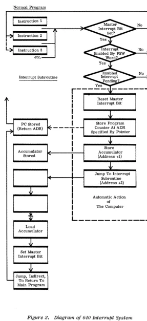
EAI 640 INTERRUPT SYSTEM
GENERAL DESCRIPTION
The Interrupt System of the EAI 640 Computer allows the programmer a choice
of interrupt priorities and actions. As the name implies, an Interrupt forces
the computer to temporarily abandon its processing of the main program to
ser-vice an anticipated condition.
Interrupts are signals which are generated internally or externally to the
com-puter by certain conditions. An internal interrupt, for example, is caused by
a memory protect violation. An example of an external interrupt would be the completion of an output through a peripheral piece of equipment causing
an interrupt on that particular channel. The 640 Computer has a Master
Inter-rupt Bit which enables or disables the interInter-rupt system of the machine. The
pro-grammer can set or reset the Master Interrupt Bit. The exceptions to this
inter-rupt procedure are the power failure interinter-rupt and the interinter-rupt test instructions
which are programmed interrupts and will be processed regardless of the setting
of the Master Interrupt Bit (Figure 2).
The Program Status Word (K Register) contains the enable/disable bits for each
interrupt level. The programmer can "mask" the interrupts he desires by
set-ting or resetset-ting the bits in the K Register. Priority of interrupts is on the basis
of bit position in the K Register. The PSW has the highest priority interrupts in
the most Significant bit positions.
The ability to mask interrupts through the Program Status Word allows the
pro-grammer to handle more than one interrupt. An interrupt automatically forces
the computer to store the content of the Program Counter in the memory address
specified by the Pointer. The content of the Accumulator is stored in the next
memory location. The interrupt acknowledge procedure requires 5.8
micro-seconds. The first instruction executed to pro;;ess the interrupt condition is
lo-cated at the pOinter address plus two. The Pointer itself is a fixed memory
loca-tion aSSigned to each particular condiloca-tion permitted to cause an interrupt and to
each of the 64 possible external devices.
Normal Program
I
I
L~
Instruction 1 Instruction 2 Instruction 3 etc. Interrupt Subroutine
PC Stored (Return ADR)
Accumulator Stored
Load Accumulator
Set Master Interrupt Bit Jump, Indirect,
To Return To Main Program
I
I
Reset Master Interrupt Bit Store Program Counter At ADR Specified By POinter
Store Accumulator (Address +1) Jump To Interrupt
Subroutine (Address +2) Automatic Action
of
The Computer
No No No
I
I
I
[image:18.632.181.468.92.719.2]L ___________
...J
MASTER INTERRUPT
The Master Interrupt Bit controls operation of the interrupt system. If the bit
is set interrupts are recognized as specified by bits set in the PSW. Two
in-structions control setting and resetting of the Master Interrupt Bit.
The Master Interrupt is turned off (reset) upon recognition of an interrupt. The
Master Interrupt can be set again as soon asthe mask in the PSW has been
modi-fied to take into consideration the processing of the interrupt presently under
con-sideration. The last instructions of the interrupt subroutine would normally be
to set tile Master Interrupt Bit followed by an indirect jump to the previously
stored program counter.
PROGRAM STATUS WORD (K Register)
The K Register has 16 bits of which bit 0 through 10 are used to enable or disable
corresponding levels of interrupts. If a bit in the PSW is a "1", the
correspond-ing interrupt is enabled. If the bit is a "0", the interrupt is masked (disabled).
Bit 12 is the Carry/Borrow bit, bit 13 is the Multiple Precision bit, bits 14 and
15 are condition codes which are set by arithmetic operations, and bit 11 is
vacant.
The Exchange Accumulator and PSW instruction permits the programmer to
store; modify it, or replace the present status word.
PRESERVATION OF REGISTERS DURING INTERRUPTS
On recognition of an interrupt, the Program Counter Register content is stored
at the address deSignated by the Pointer and the content of the Accumulator is
stored in the pOinter address plus 1. The only exception to this is the TRAP
in-struction which modifies the Accumulator before it is stored. In the case of the
TRAP, bits 8 through 15 of the Accumulator are set to equal the same bits of the
instruction. The instruction will set bits 0 through 7 of the Accumulator to zero.
Trap instructions can thus be numbered up to 256 (377 8),
PRIORITY
Priority is established by bit position in the PSW, with the PSW bit zero having
the highest priority. A further priority assignment is made in the case of
pe-ripheral equipment by the position of the device on the standard data channel or
INTERNAL INTERRUPTS
Internally generated interrupts have the highest priority. Internal interrupts
are ignored and do not remain pending if the Master Interrupt Bit is reset or bits
o
through 4 of the PSW are reset. The single exception to this is the interval timer interrupt (bit 5 of PSW) which will remain pending until serviced.The Internal Class of interrupts consists of: Bit
o
Trap Instruction 1 Illegal Instruction2 Illegal Procedure in Setting/Resetting Protect Bit
3 Memory Protect Violation
4 Machine Check and I/O Parity
5 Interval Timer (Up to Four, Optional)
EXTERNAL INTERRUPTS
There may be up to 64 peripheral devices, each with its own unique interrupt
service, on the I/O data channel. Data channel class interrupts are divided into
four groups (Data Channel Interrupt 0 through 3). These interrupts will remain
pending even though the Master Interrupt Bit is reset or bits 6 through 10 of the
PSW are reset. Priority among Data Interrupt Channels is established by their
bit position in the PSW
The external class of interrupts consists of:
Bit
6 Data Interrupt Channel 0
7 Data Interrupt Channel 1
8 Data Interrupt Channel 2
9 Data Interrupt Channel 3
10 Alarm Channel Interrupt
On each of the four Data Interrupt Channels, an additional ordering of priority is
provided for peripheral equipment by the position of the 16 possible devices on
each interrupt line. On each interrupt line, that device which is connected
near-est to the computer is given the highnear-est priority on that Data Interrupt Channel.
This provides for future re-ordering of priorities and adding additional
ABSOLUTE PRIORITY
The interrupt test instructions and the power failure interrupt have absolute pri-ority in that neither the PSW nor the Master Interrupt can prevent them from oc-curring. The interrupt test instructions are programmed interrupts placed at pre-determined locations in a program and thus will not interfere with normal processing.
POINTERS
The fixed assignment of a core memory location which is made for each inter-rupt is designated as Pointer. The pointer registers must be loaded by the pro-gram with an address to which the computer will automatically go upon recogni-tion of an interrupt.
DESCRIPTION OF INTERRUPTS
Power Failure Interrupt
The absolute priority interrupt is given to the power failure condition. If the com-puter should sense line voltages above 135 volts or below 100 volts for more than 100 milliseconds, this interrupt will be generated and the I/O instruction in pro-gress will be immediately interrupted. The content of the Program Counter Register and Accumulator will be automatically stored. There is sufficient time (2 milliseconds minimum) before computer operation stops for the interrupt rou-tine to retrieve and store the content of the three additional hardware registers.
Trap Instruction
The Trap instruction modifies Accumulator bits 8 through 15 and sets bits 0 through 7 to zero. Bits 8 through 15 can be used to code the instruction from 0 to 25610. The Trap instruction is considered a program generated interrupt.
Illegal Instruction
This interrupt occurs when the control section of the 640 Computer cannot decode the operation code of an instruction as a legal bit combination.
Illegal Procedure in Setting/Resetting Protect Bit
An interrupt is generated when the Memory Protect Switch on the console is in the "OFF" position and the program attempts to set or reset a protect bit. Nei-ther instruction will be executed before the interrupt occurs.
Memory Protect Violation
A program in an unprotected area of core memory has attempted to alter a core
location which has the protect bit set. An interrupt occurs and no storage
alter-ation will take place.
Machine Check or 1/0 Parity
This interrupt occurs on a parity failure in data transmission from a peripheral
device or a device fails to respond properly.
Data Interrupt Channel 0 through 3
A data channel interrupt is generated by one of the peripheral devices on the data
channel.
Alarm Channel
The interrupt on Alarm is generated by a peripheral device which is attached to
the Alarm Channel. Only special features of the device are recognized as alarm
conditions and are signaled through this channel. Generally, it can be stated that
an alarm condition is one that would defeat the operation of the peripheral device
EAI 640 MEMORY PROTECT SYSTEM
The program protection system of the EAI 640 Computer makes it possible to
pre-vent storage locations in core memory from being modified by a non-protected
program. The system is based on the presence of a "protect bit" for each storage
location in core memory. Operation of the protect system involves a switch on
the control panel console, two instructions from the repertoire, the contents of
the Index Register (X) and the Accumulator. Violations of memory protection are
signaled through the interrupt system.
The Memory Protect Bit can be set or reset only if the "Memory Protect" switch
on the control panel console is in the ON position at the time the instruction is
ex-ecuted. The least significant 15 bits of the Index Register (X) added into the
con-tents oftheAccumulator specify the address ofthe core memory location which is
to have the protect bit set or reset.
If the "Memory Protect" switch on the control panel is in the OFF position when
a set or reset protect bit instruction is attempted, an Illegal Procedure interrupt
will be generated.
changed.
The protect bit of the specified memory location will not be
A protected instruction (one which has its protect bit set) may reference another
protected instruction or data operand. The protected instruction is therefore
privileged. An unprotected instruction may not change a protected core memory
location. An attempt to do so will result in a Memory Protect Violation interrupt.
1"'1
~
I~
3: 1"'1 3:
o
:::a -<
"
:::ao
-I
1"'1 (")
-I
(I) -< (I)
-I
EAI 640 INPUT/OUTPUT SYSTEM
INTRODUCTION
The EAI 640 Computer can handle input/output in three modes:
one word at a time through the Accumulator
a complete record through the Accumulator and Q Registers directly to or
from memory
a buffered record directly to memory (Optional feature)
The standard I/O data channel handles transfers in Single Word Mode or Record
Mode. The single word mode and the record mode stop computation because the
Accumulator is used for transfers. The difference between single word mode and
record mode lies in the convenience of programming. The former requires a
loading or storing of the Accumulator for each one word transfer. The latter runs
to completion once the program has specified the beginning and end of the memory
area to be input or output. An optional buffered I/O channel provides for Direct
Memory Access. The buffered data channel operates on a "cycle stealing" basis
permitting computation to continue while I/O operations proceed independently.
The EAI 640 can operate both the buffered data channel and the standard data
channel simultaneously.
Operation of peripheral devices is initiated through Device Function instructions.
The data path is established and the equipment instructed on the action to be taken.
Through the Status Input instruction the peripheral equipment can inform the
com-puter about existing conditions. Interrupts are used to signal termination of I/O
either normally, or through some abnormality such as a parity or protect violation.
Should the interrupt system be disabled by the program, either through the masking
of the interrupt or the resetting of the Masterlnterrupt, the peripheral device can
be tested for an interrupt through the Test Device Interrupt instruction.
SINGLE WORD MODE INPUT/OUTPUT
The two instructions, Data In and Data Out, cause a 16-bitparallel word transfer
between the Accumulator and a specified device on the standard data channel.
These two instructions, together with store or load Accumulator and skip on in-dex permit successive word transfers from or to all core memory locations. The single word input/output mode is generally used in communications with low speed devices. This mode of input/output permits many instructions to be exe-cuted between data transfers.
RECORD MODE INPUT jOUTPUT
The two instructions, Record In and Record Out, cause 16-bit parallel word transfer between core memory and a specified device on the standard data channel. When operating in the Record Mode, the running program is halted and the processor devotes full time to information transfer from or to a peripheral device. This mode of input/output is generally used in communication with devices having a high transfer rate.
Record Packets
The Record Mode instructions operate under the control of four input/output pack-ets each consisting of four aSSigned core memory locations. The packets are numbered zero through three. The four core memory locations assigned for each packet are used as follows:
Device Function Word Final Record Address plus 1
Starting Record Address
Ilo
Termination AddressBefore execution of a Record Mode instruction, the program must initialize the
Device Function Word, the Final Record Address, and the Starting Record Ad-dress words. When a Record Mode instruction is executed, the Device Function Word is sent to the specified device and the desired mode of operation begins. Data is then transferred from or to the Starting Record Address location and con-tinues a word at a time until the Final Record Address is reached unless the de-vice terminates transmission of data. The Terminating Address of the last word transmitted is then stored in the last word of the packet.
Address will be less than the Final Address. If the actual record length is equal
or longer than called for, the Terminating Address will be the same as the Final
Address. To sense a longer length record, the program must sample the Device
Status Word.
DIRECT MEMORY ACCESS CHANNEL (DMAC)
General
The Direct Memory Access Channel (640/310) provides a direct data path between
various peripheral equipment and the memory of the 640 Computer. As a logical
device the DMAC will control the input/output of data, the core memory locations
accessed, the record length as well as check for correct transmission parity,
vi-olation of memory protection and control over device interrupts. The DMAC
per-forms these functions independent of program control.
Functional Description
The DMAC operates on a cycle-stealing basis, stealing memory cycles from
nor-mal program execution when input/output data is ready for transfer to or from
memory. Data is held in the DMAC's data register and the memory address in
an address register while the DMAC steals a memory cycle. Instruction
execu-tion in the computer is suspended during a cycle steal but resumes automatically
when the steal cycle is complete. The address register is incremented at the end
of each steal and compared with a second address register in the DMAC containing
the final address of the record. When the two address registers compare equal
the DMAC becomes inactive and an interrupt is generated.
The DMAC will steal a cycle if the computer has not already entered into a
mem-ory read cycle. The data path through the DMAC is a full 16-bit word and is
transferred in parallel. While the DMAC is active, the computer may access its
current address register to determine how much progress has been made on the
data transfer.
Initialization
The DMAC is initialized by the execution of a Buffered Record Input or a Buffered
Record Output instruction. These instructions will load starting and final
-dresses into the DMAC and set it in motion as specified by the Device Function
word. The four core memory locations of record packets 00 through 03 are
as-signed as follows for the Buffered Record Mode:
Device Function Word
Final Record Address
Starting Record Address
Not Used
Buffered Record Transfer
The Buffered Record Mode instructions cause an autonomous record transfer.
The transfer operates in a cycle-stealing mode interleaving high speed input/output
operations with computation in the central processor. Transfer is initiated by
the computer and is terminated by the DMAC. Record transfer termination is
accomplished when a full record is transferred as defined by the Starting and
Final Addresses.
Peripheral Equipment
All operating functions of a particular peripheral device work normally on the
DMA channel. The only apparent difference between systems with and without the
DMA channel is the overall decrease in program running time due to increased
efficiency of input/output housekeeping operations.
Only one DMAC peripheral device can be active at anyone time but may be either
input or output. Standard I/O operations do not interfere with an active DMAC.
The DMAC will continue to transmit data when the computer is in PAUSE condition.
No more than one DMAC can be installed in a640 System. The maximum number
of peripheral devices has not doubled with the addition of the DMAC. The total
remains at 64, with the further requirement being that no device on the standard
channel may have the same device address as a device on the DMA channel. A
device may not be connected to both channels at once. A requirement of the DMAC
is that the interrupt line on the DMA channel be separate from the standard
Interrupts
If the DMAC option is installed, data interrupt channel 2 is assigned to those
de-vices attached to the DMAC I/O Interface, while interrupt channels 0, 1, 3, and Alarm remain assigned to devices on the standard channel.
An interrupt on the DMAC is processed in the same way as a standard interrupt,
and at the end of the next instruction if the interrupt is not masked, the computer replies with an interrupt acknowledge. The first device on theDMA device chan-nel that has an interrupt pending sends back its device address, from which the computer derives the pOinter address. Important to note here is that the inter-rupt may have originated in a device other than one with which the DMAC is transferring data, and that action on the interrupt will remain pending until the DMAC goes inactive.
Parity
Like the standard channel, the DMA channel allows for the transmission and checking of parity along with the data. The DMAC generates parity on output and the device mayor may not check it according to its design. The device, if it is so designed, will generate parity on input and the DMAC will check it. Parity checking is controlled by the parity inhibit line. An interrupt on parity error from the DMAC is the result of a parity error on input data. An interrupt on par-ity error from a device controller would be the result of a parpar-ity error on output
data. There is no parity transmitted between the DMAC and the computer, nor between the DMAC and memory.
Memory Protect
Buffered Record Mode Instructions maybe flagged as privileged, and upon execu-tion, a flag is set in the DMAC. If so, any input data is stored into memory with-out violating memory protection. If the instr-uction is not privileged, an attempt to store data into a protected cell will result in a protect violation. This situation is detected by the DMAC and an interrupt occurs if the interrupt on protect viola-tion was selected. The content of the protected cell is preserved and the input data that would have been stored there is lost; the DMAC will not allow the protect bit itself to be altered, whether the instruction is privileged or not.
Data Rates
The DMAC will transfer data ata maximum rate of 600, 000 words per second. For any free running device to operate at, or near this data rate, sufficient buffering
EAI 640 INSTRUCTION REPERTOIRE
The EAI 640 Computer has a flexible repertoire of 64 hard-wired instructions.
These can be grouped conveniently into twelve functional categories:
Transfer instructions which communicate between core memory and the
accumula-tor or index register. Transfer between memory and the index register does not
affect the contents of the accumulator.
Arithmetic instructions include full word add and subtract; double word result after
multiply, divide and square root; increment accumulator, clear accumulator,
clear and add one, and two's complement accumulator. Any core memory
regis-ter can become a counregis-ter by use of the Add One toMemory and Skip instruction.
Logical instructions include OR, XOR, AND, Compare and One's Complem ent Ac-cumulator.
Shift instructions operate on the accumulator alone or across the combined accu-mulator and accuaccu-mulator extension register. Shifts are right or left, single or
double, arithmetic or logical.
Control instructions set or reset the multiple precision bit or set the sign of the accumulator positive or negative. Pause, Trap and No Operation are included in
this group.
Interrupt instructions set or reset the Master Interrupt Bit to permit or inhibit· interrupts according to the structure of the Program Status Word (K register).
Program Protect instructions set or reset the program protect bit of the core mem-ory location specified by the index register if the console memmem-ory protect switch
is ON.
Jump and Skip instructions include jump with link to provide a stored program
counter register for subroutine entry, and skip on sense switchor multiple sense
switches. Unconditional jump and skip instructions are also included.
SkiP on Register Condition instructions operate on accumulator positive or
nega-tive and accumulator or accumulator extension register even. Skip instructions
also increment or decrement the index register and skip if the sign of the index
register changes.
Skip on Condition Code instructions test two bit positions of the program status word. These instructions are only valid following certain arithmetic, shift, and
logical operations.
Input/Output instructions are grouped into single word mode, record mode, and buffered record mode. Single word mode causes I6-bit parallel transfer of data
between the accumulator and a specified device on the standard data channel.
Re-cord mode causes I6-bit parallel transfer of data directly between core memory
and a specified device on the standard data channel. Record mode data transfer
continues a word at a time until all data between the starting and final record
ad-dresses has been transmitted.
The buffered record mode operates in a similar manner except that transfer of
data from core memory to a specified device on the buffered data channel occurs
on a cycle stealing or "interleaving" basis. The Direct Memory Access Channel
performs the logical input/output control functions independent of program
Mnemonic Code. TRANSFERS LA STA LX STX ARITHMETIC A S M D SQR ADA ADM TCA CLR CAD LOGICAL OR XOR AND C DCA SHIFTS ARS ALS ARD ALD LRS LLS LRD LLD
FUNCTION LISTING OF EAI 640 INSTRUCTIONS
Instruction Description
Load Accumulator
Store Accumulator
Load Index Register
Store Index Register
Add
Subtract
Multiply
Divide
Square Root
Add One to Accumulator
Add One to Memory and Skip
Two's Complement Accumulator
Clear Accumulator
Clear Accumulator and Add One
Or (Logical Sum)
Exclusive Or (Logical Subtract)
And (Logical Product)
Compare
One's Complement Accumulator
Arithmetic Right Single
Arithmetic Left Single
Arithmetic Right Double
Arithmetic Left Double
Logical Right Single
Logical Left Single
Logical Right Double
Logical Left Double
Note (1): 1.65 ",sec minimum for a single shift.
Time In Microseconds 3.30 3.30 3.30 3.30 3.30 3.30 18.15 18.975 16.5
1. 65
4.95
1. 65
1. 65
1. 65
3.30 3.30 3.30 3.30
1. 65
See Note (1) Below
FUNCTION LISTING OF EAI 640 INSTRUCTIONS (Cont)
Mnemonic Code
.
CONTROL SMP RMP SSP SSN NOP P T INTERRUPT SM! RM!PROGRAM PROTECT
SPB RPB EXCHANGES EX
EQ
EP ESJUMPS and SKIPS
J
L
SSW
SKU
SKIP ON REGISTER CONDITION
ICX
Instruction Description Microseconds Time In
Set Multiple Precision Bit, Reset Carry/Borrow Bit
Reset Multiple Precision Bit
Set sign of Accumulator Positive
Set sign of Accumulator Negative
No operation
Pause
Trap
Set Master Interrupt Bit
Reset Master Interrupt Bit
Set Protect Bit
Reset Protect Bit
Exchange Accumulator and Index Register
Exchange Accumulator and Q Register
Exchange Accumulator and Program Counter
Exchange Accumulator and Program Status Word
Jump Unconditional
Link
Skip on Sense Switch
SW A+200 E+I0 B+100 F+ 4 C+ 40 G+ 2
D+ 20 H+ 1
Skip Unconditional
Increment Index and Skip
1. 65
1. 65 1. 65 1. 65 1. 65 1. 65 1. 65
1. 65 1. 65
3.30 3.30
1. 65
1. 65
1. 65
1. 65
1. 65 3.30 2.475
2.475
FUNCTION LISTING OF EAI 640 INSTRUCTIONS (Cont)
Mnemonic Code
SKIP ON REGISTER CONDITION (Cont)
DCX
SKN
SKP
SAE
SQE
SKIP ON CONDITION CODE
Instruction Description
Decrement Index and Skip
Skip if Accumulator Negative
Skip if Accumulator Positive
Skip if Accumulator Even
Skip if Q Register Even
Class 1: Valid following A, S, AOA, TCA
SZ Skip if result was Zero
SP SM SO SNZ SNP SNM SNO SPZ SMZ SZO SPM SPO SMO
Skip if result was Plus
Skip if result was Minus
Skip if result caused Overflow
Skip if result was Not Zero
Skip if result was Not Plus
Skip if result was Not Minus
Skip if result did Not cause Overflow
Skip if result was Plus or Zero
Skip if result was Minus or Zero
Skip if result was Zero or causes Overflow
Skip if result was Plus or Minus
Skip if result was Plus or caused Overflow
Skip if result was Minus or caused Overflow
Class 2: Valid following M and D
SO Skip if result caused Overflow
SNO Skip if result did Not Cause Overflow
Class 3: Valid following OR, XOR, and AND
SZ Skip if result was Zero
SNZ Skip if result was not Zero
FUNCTION LISTING OF EAI 640 INSTRUCTIONS (Cant)
Mnemonic Code Instruction Description
Class 4: Valid following C
SE
SG
SL
SNE
SGE
Skip if Operands Equal
Skip if accumulator was Greater
Skip if accumulator was Less
Skip if accumulator was Not Equal
Skip if accumulator was Greater or Equal
SLE Skip if accumulator was Less or Equal
Class 5: Valid following ALS and ALD
SO SNO SAO NAO INPUT/OUTPUT DI DO RI RO DF SI
Skip if result caused Overflow
Skip if result did Not cause Overflow
Skip if result is About to Overflow
Skip if result is Not About to Overflow
Data Input
Data Output
Record Input
Record Output
Device Function
Status Input Time In Microseconds 2.475 2.475 2.475 2.475 2.475 2.475 2.475 2.475 2.475 2.475 3.30 3.30
6.6 + 1. 65 per Word
6. 6 + 1. 65 per Word
3.30
3.30
Test Device Interrupt (Not Pending)2. 47
(Pending) 7. 42
TTl
TDI
TAl
Timer Channel
Channel Zero
Channel One
Channel Two or DMAC Devices
Channel Three including Teletype
Direct Memory Access Controller
FUNCTION LISTING OF EAI 640 INSTRUCTIONS (Cont)
•
Mnemonic Code Instruction Description Microseconds Time In
INPUT /OUTPUT (Cont)
BRI Buffered Device Input 6.6 + 1. 65 per
Word
BRO Buffered Device Output 6.6 + 1. 65 per
Word
BDF Buffered Device Function 3.30
section
EAI 640 PERIPHERALS DESCRIPTION
INTRODUCTION
Selection of peripheral devices for an EAI 640 Digital Computing System is
op-tional on the part of the user with a single requirement. The 640 Programming
Systems require a keyboard/typer and a paper tape reader and punch as a
mini-mum for operation. This requirement can be met in one of two ways:
(1) By an ASR Teletype (Model 330r35)to provide a keyboard/typer, paper tape
reader and punch in a single unit.
(2) Or by a KSR Teletype (Model 33 or 35) to provide the keyboard/typer along
with a high speed paper tape reader and punch separately housed.
A maximum of 64 device controllers can be attached to the EAI 640 Computer. These may be distributed within the four data channel interrupt levels to meet
the individual system requirements.
640/960 FLOATING POINT PROCESSOR
The 640/960 Floating Point Processor (FPP) is a peripheral device that augments
the 640 Digital Computing System with high speed 32-bit single precision floating
point capability. The FPP operates independently of the 640 qentral Processor
(CPU) and is controlled through the standard Input/Output Channel.
A 32-bit (24-bit mantissa, 8-exponent) accumulator is included in the FPP which
can be loaded by two Data Output (DO) instructions and then operated upon.
Con-trol of the FPP operation is achieved by the Device Function (DF) instruction.
Once an operation is initiated, the FPP will compute independently of the Central
Processor which is then free for other computation.
For maximum high speed performance, the FPP contains a buffer register for
data words to permit overlapping an FPP computation with data loading for the
next computation.
The Central Processor can test the status of the FPP at any time through the
Status In (SI) instruction. After the FPP has completed the current operation,
the result is stored in its accumulator. This result can either be operated upon
or input to the Central Processor through two Data Input (DI) instructions.
Data Format
Each single precision floating point word consists of two 640 data words which have
the following format.
Word I
Most Significant Mantissa
Word II
Least Significant
o
Mantissa 7 Exponent 15Since the single precision floating point format requires two 640 data words, the
execution of 2 Data Output Instructions is required to transmit data to the FPP,
and the execution of 2 Data Input Instructions is required to receive results from
the FPP.
Commands and Timing
Execution Time* In Microseconds
Command Min Max
Floating Clear and Add 1.0 1.5
Floating Clear and Subtract 1.0 L5
Floating Add LO 6.0
Floating. Subtract 1.0 6.0
Floating Multiply 5.5 11. 0
Floating Divide 9.0 11. 0
Control Word Format
OP Code
3
B = busy
N = normalize
MSA
=
2nd operand is accumulatorE = enable exponent fault interrupt
R
=
round bitPC
=
fault codeF
=
fault occurred, generate interrupt if E is setSoftware
Spare
12
A modified Run Time Library will be supplied with the FPP, so that FORTRAN
object programs can take advantage of the FPP when performing single precision
floating point addition, subtraction, multiplication and division.
Note that the use of subroutines in the modified Run Time Library can be called
from Assembly language programs which will utilize the higher speed of the FPP
for the following functions.
(1) Floating Clear and Add
(2) Floating Store
(3) Floating Add
(4) Floating Subtract
(5) Floating Multiply
(6) Floating Divide
Physical Requirements
The Floating Point Processor is housed in the 640/910 Expansion Rack. Has
self-contained power supply capable of operating on 50/60 Hz, 115/230 volts.
640/260
DATA DISC STORAGE SYSTEM
The 640 Data Disc storage System provides bulk storage of information with rapid and random access. Each 640/262 Data Disc Drive provides direct access to 360, 448 sixteen-bit words of information. The disc drive utilizes the design principle of a permanent read/write head posi-tioned over each information track. The result is an all-electronic track access, significantly faster and more flexible than conventional disc files. Average access time is 17 milliseconds.
The 640/260 Data Disc Controller operates up to four 640/262 Data Disc Drives for a total capacity of 1,441,792 sixteen-bit words per control-ler. Data validation is provided in the controller by calculating and recording a 16-bit cyclic check word for each block written and calcu-lating and comparing the cyclic check word for each block read. In addition, the controller generates and checks the parity of data trans-mission between the controller and computer.
Protection of information on the disc is provided by allowing 16-sector blocks of data to be recorded as protected. Writing on these blocks is prohibited as long as the unprotect switch on the disc drive console is
not set. Writing on protected tracks is permitted only when the unpro-tect switch is set by the operator and a prounpro-tect override command is furnished by the computer program. This feature provides for the pro-tection of system software and user libraries.
The disc has 64 tracks, each track has 128 sectors which are
individu-ally addressable, and each sector holds 44 words plus one cyclic check
word.
Transfer Rate is 3 million bits/second.
Average Access (latency) time is 17 milliseconds.
The Data Disc Controller and up to two Data Disc Drives are mounted in one disc storage cabinet. Communications with the 640 computer maybe through either the Standard or Direct Memory Access Channel.
TELETYPE WRITER STATION
640/410
640/411
640/412
640/413
TELETYPE UNIT (33 KSR)
TELETYPE UNIT (33 ASR)
TELETYPE UNIT (35 KSR)
TELETYPE UNIT (35 ASR)
A selection offour Teletype units is available with the EAI 640 System. Model 33 is the light duty Teletype unit, while Model 35 is the ruggedized version. The KSR (keyboard send-receive) Teletype units provide for keyboard input and typer output, while the ASR (automatic send-receive units include a paper tape reader and paper tape punch.
The keyboard and typer operate in ASCII code at 10 characters per sec-condo The tape reader and punch operate in any code at 10 characters per second.
PAPER TAPE STATION
640/420
640/421
640/422
PAPER TAPE CONTROLLER
PAPER TAPE READER
PAPER TAPE PUNCH
The high speed Paper Tape Reader provided with the EAI 640 System is capable of reading 5, 7, or 8 level punched paper tape at300 charac-ters per second in a forward direction only.
The high speed Paper Tape Punch is capable of punching 5, 7, or 8 level tape at 120 characters per second.
The Paper Tape Controller handles a maximum of one tape reader and one tape punch. The reader or punch can be purchased separately at
the customer's option.
The high speed paper tape units can be housed in a standard equipment cabinet or in the desk console equipment cabinet.
640/520
CARD READER
The Punched Card Reader provided with the EAI 640 System reads stan-dard 12 row, 80 column cards at a rate of 400 cards per minute. Cards
are read column by column; the original deck orientation is maintained in the output hopper after reading. Cards may be loaded or unloaded concurrent with card reader operation so as not to interfere with over-all system efficiency. The card reader has an input hopper capacity of
640/610
LINE PRINTER
The Line Printer provided with the EAr 640 System prints 120 columns
(136 optional) at a speed of 300 lines per minute, from a full line buf-fer. The Line Printer has 64 characters printing 6 lines per inch; vertical format is controlled by a closed loop tape moving
640/720
MAGNETIC TAPE
CONTROLLER & TRANSPORT
The Magnetic Tape Controller is capable of operating up to four
magne-tic tape transports. The Tape Transports are available for either of the two most common recording formats - 7 track IBM compatible and 9 track which is compatible with the IBM 360 System.
640/720
640/721
640/730
640/731
Magnetic Tape Controller and one 9 track
Magnetic-Tape Transport
Magnetic Tape Controller and one 7 track
Magnetic Tape Transport
Magnetic Tape Transport (9 track)
Magnetic Tape Transport (7 track)
Both the 9 or the 7 track Magnetic Tape Transports operate at 45 inches per second. Recording density is selectable at 200, 556 or 800 bpi with a switch and can be tested by the computer program with a Status Input.
The tape controller can be used with either the 7 channel or the 9 chan-nel transport units exclusively, or intermixed. The program in the computer can test through a Status Input whether a given tape transport is 7 or 9 track. Tape units can be field modified from either configura-tion to the other by replacing the read/write head.
Two markers are sensed on the magnetic tape. The Beginning of Tape (BOT) also referred to as "Load Point" is indicated by a reflective marker on the edge of the tape. The tape can be positioned on the mark-er or it can be rewound to the markmark-er undmark-er program control. The End of Tape (EaT) marker can also be sensed by the computer program through an Interrupt.
The computer can also request that interrupt be generated when the Magnetic Tape Controller detected an End of Record mark on the Tape.
The Magnetic Tape Transports can read in a forward or reverse direc-tion. Writing is only permitted in the forward direction of tape travel. The controller is capable oftransferring data in 8 or 16-bit mode. As-sembly-disassembly occurs in the 16-bit mode. Vertical tape parity can be selected under program control as "Even" or "Odd".
The Magnetic Tape Transport can be commanded to skip one record on the tape in either a forward or a reverse direction. A complete file can also be skipped. Should the Magnetic Tape develop a bad spot, a com-mandis available to skip 3.75 inches in a forward direction. An End of File mark can be written under program control after which the trans-port stops the tape movement.
EAI 640 SYSTEM CONFIGURATOR
r - - - -
--ST-:;;;D:;D-;,~O_;;A~;_- - - ,
I
I
I
I
I
I
I
I
L Memory Bank4,096 Words of Core Storage (640/004 or 014) (Note 1)
4,096 Words of Additional Core storage (640/204).
Convert to 8, 192 Words
Total. (640/008 or 018) (Note 1)
8,192 Words of Additional Core storage (640/208). Convert to 16,384 Words Total. (Note 1)
16,384 Words of Additional Core Storage (640/216). Convert to 32,768 Words Total. (Note 2)
(640/610)
I+-~ ~
Processor Data Exchange
·
Hardware Multiply, Divide, and Square Root·
Four Data Channel Levels, up to 64 Peripheral Devices·
Memory Protect·
Five Masked External Interrupts·
Index Register·
Expanded Input (18 Bit from Analog Device)·
Six Masked Internal Interrupts·
Timer Interfaces·
Rack Mounted Control Panel (640/004)·
Parity Check·
Teletype Controller·
Device Alarm ChannelOptional: Data Channel
I
Timer 3 2 1 0 A·
Desk Console with Mounted Control Panel (640/014) Levels Interface- - - -
- -
-
-
-
-(640/262) Maximum of 4 Disc Drives per Controller
Direct Memory Access Channel
High Speed Input/Output Data Transfer Channel Operating on a Cycle Stealing Basis. Maximum of One (1) per 640 System. (640/310) (Note 1)
--
Teletype 33 or 35,ASR or KSR.
One Required (Four +--+ Device Addresses) (640/410, 411, 412, 413)
Up to 64 Peripheral DevIces. Direct Memory Access Devices, if Present, Connect to Channel 2
(640/720, 640/721)
(Additional Transports 640/730, 731) (640/422) (640/550) (640/520)
I
I
I
I
I
I II
_...JNOTE 1:
NOTE 2,
NOTE 3,
NOTE 4,
Floating Point Processor
(Note 4)
(640/960)
Component is Mused in Central Processor Rack.
Component is housed in a standard Expansion Rack: does not require Dellice Controller Power Supply.
Component may be housed in desk pedestal or a standard Expansion Rack: does not require Device Controller Power Supply.
section
EAI 640 SYSTEM SOFTWARE
EAI 640 SYSTEM SOFTWARE
The 640 Programming System is an integrated set of computer programs
provid-ing efficient, reliable operation of the EAI 640 Digital Computprovid-ing System.
The descriptions which follow provide an understanding of the software
capabili-ties available with the EAI 640 Computer and detail the minimum components
re-quired for operation.
SYMBOLIC ASSEMBLER
The Symbolic Assembler permits the user to code instructions in a symbolic
language using mnemonic symbols of instruction codes and addresses. In
addi-tion to the 64 basic instrUcaddi-tions, the Assembler also provides a powerful set of
pseudo-operations for program control, data definition, storage allocation,
input/output functions, and subroutine calls.
The Symbolic Assembler provides a two-pass operation and produces a relocatable
object program, program listing, and diagnostic messages.
Available Assembly options include:
(1) inhibit program listings and provide error listing only
(2) output object code in relocatable form
(3) output object code in absolute form (binary)
A variety of peripheral device options are available besides the minimal teletype
input/ output device. These options are:
Input source program from:
Teletype paper tape reader
High speed paper tape reader
Card Reader
Output object program to:
Teletype paper tape punch
High Speed paper tape punch
Magnetic Tape
Data Disc
Program listings may be printed on:
Teletype printer
Line printer
The determination of which devices are to be used by the assembler is designated
by the assembler I/O control package.
Minimum Operating System
640/008 or 018 EAI 640 with 8K words of core memory.
640/411 or 413, Model 33 or 35 ASR Teletype
ASA STANDARD FORTRAN
FORTRAN permits the user who has little knowledge of the computer's
organiza-tion or machine language to write programs in a language consisting of English
words and mathematical symbols. EAr 640 FORTRAN IV is designed for maximum