FPGA IMPLEMENTATION TO MINIMIZE
TORQUE RIPPLES
IN PERMANENT MAGNET SYNCHRONOUS MOTOR
DRIVEN BY FIELD ORIENTED CONTROL USING FUZZY
LOGIC CONTROLLER
1B.ADHAVAN, 2Dr.C.S.RAVICHANDRAN
1,2Department of EEE (PG), Sri Ramakrishna Engineering College, Coimbatore, Tamilnadu, India: 641022.
E-mail: 1 [email protected] , 2 [email protected]
ABSTRACT
The Permanent Magnet Synchronous motor is a rotating electrical machine where the stator produces a sinusoidal flux density distribution in the air gap and the rotor has permanent magnets. A substantial air gap magnetic flux generated by permanent magnet makes it reliable to design highly efficient motors. However, the main disadvantage is the non-uniform variance in the developed torque. These torque ripples causes speed oscillations and vibrations and perverts the system performance. Since the construction of permanent magnet synchronous motor lacks rotor coil which will provide mechanical damping during transient conditions, these motors are inefficient with open-loop V/Hz control and rely on Vector Control for better dynamic response. Fuzzy logic controllers which does not requires any modeling of a system based on mathematics and are they are working on the linguistic rules. It also improves the performance of PI controllers which are affected by load turbulence, parameter variations and speed disturbances. This project presents the Fuzzy logic approach for a vector controlled PMSM drive for minimizing torque ripples. Also, Space vector modulation is employed to overcome the periodic torque pulsations generated by hysteresis controllers. The design analysis and the hardware control are implemented by using FPGA controller and discussions on the hardware results are done.
Keywords: Permanent Magnet Synchronous Motor (PMSM), Field Oriented Control (FOC), PI
controller, Fuzzy Logic Controller (FLC), Field Programming Gate Array (FPGA), Space Vector Pulse Width Modulation(SVPWM).
1. INTRODUCTION
Permanent magnet synchronous motor (PMSM) is a hybrid of an AC induction motor and a Brushless DC motor. They have rotor which contain permanent magnets and it is similar to that of a BLDC motors. These PMSMs are extensively utilized in small and medium power applications such as Robotics, Computer peripheral equipment’s, Adjustable speed drives and Electric vehicles due to the advantages like high efficiency, high power factor, high power density, compactness and maintenance free operation. Also these motors are preferred over the traditional brush-type dc motors because of the absence of mechanical commutators, which reduces mechanical wear and tear of the brushes and increases the life span of the motor. However, the main disadvantage of PMSMs is the parasitic torque pulsations. Presence of these torque pulsations results in instantaneous torque that
pulsates periodically with rotor position. These pulsations are reflected as periodic oscillations in the motor speed, especially for low-speed operation.There are various sources of torque pulsations in a PMSM such as the cogging, flux harmonics, errors in current measurements, and phase unbalancing. In view of the increasing popularity of PMSMs in industrial applications, the suppression of pulsating torques has received much attention in recent years.
ISSN: 1992-8645 www.jatit.org E-ISSN: 1817-3195
is that the practical implementation of the model requires additional work [9].
The torque ripples are parasitic and can lead to torque pulsations, vibrations and noise. The complex state variable technique is used for modeling and analyzing the effects of parasitic torque. The compensation of parasitic torque ripples is by producing high frequency electromagnetic torque components through current control system [8]. A numerical predetermination of the current waveform is imposed in phases of machine to attain a steady torque. Torque regulation scheme is based on-line instant estimation. The optimization of the current and minimization of copper losses is done by current modulus minimization and the results are compared. The optimization of current function optimizes the mean torque, such that torque ripple is minimized [5].
A new inverter output filter topology is designed to reduce the high frequency harmonics which reduces the breakdown strength of insulation and reduces insulation life and causes severe damage to the motor bearings. These output filters reduce the phase shift in the current regulating system and torque ripple respectively and improves the filter efficiency [17].
An embedded phase domain model of PMSM, which reduces instabilities due to numerical. Both the conventional and embedded phase domain models of PMSM shows indistinguishable results in the steady state and transient conditions, however the conventional model of PMSM becomes unstable if the time-step is increased [6].
Torque ripple diminishing in a permanent magnet synchronous motor with non ideal back electromotive force. In order to achieve constant torque with reduced torque ripples improved current tracking in the presence of periodic reference signals and disturbances is proposed by the application of current repetitive techniques in a field-oriented PMSM drive [13].
To diminish the torque ripples and harmonic noises in PMSM an active filter topology. The hysteresis voltage control method is used in active filter, while the motor current uses the hysteresis current control method. The simulation results show that the total harmonic distortion goes below 13% with EMI noise damping down to nearly to -10 dB [7].
An application of computational intelligence techniques like fuzzy logic is used to reduce the torque ripples associated with direct torque control in PMSM [12].
2. FIELD ORIENTED CONTROL
The primary limitation of sinusoidal commutation is controllig motor currents which are time variant in nature. This breaks down as speeds and frequencies increases due to the restricted bandwidth of PI controllers. This problem can be solved by controlling the current space vector directly in the d-q reference frame of the rotor which is known as Vector Control or Field Oriented control or Decoupling control.
Field-oriented control is an efficient method to control a PMSM in adjustable speed drive applications with quickly changing load in a wide range of speeds including high speeds where field weakening is required. It demonstrates a synchronous motor to be controlled like a separately excited dc motor by the orientation of the stator mmf or current vector in relation to the rotor flux.
Field oriented control consists of vectors to control the stator currents. The field oriented control is based on transforming a three phase coordinates systems which are time and speed dependent into d and q co-ordinates (two co-ordinate system) time invariant system. The DC machine type control is achieved through these projections of three phases to two phase conversions.
Field oriented controlled machines require two constant input references; they are the torque component which is aligned with the q coordinate and the flux component which is aligned with d co-ordinate. This makes the field oriented control system precise in all working modes (transient and steady state) and unlimited bandwidth compared to limited bandwidth in mathematical model. The Field Oriented Control solves the following steps: 1. Finding the constant reference of flux component and torque component of the stator current.
2.Calculation of torque from (d,q) reference frame by applying direct torque control and the expression of torque is given by
T αΨR isq (1)
The linear relationship of torque and torque component (isq) can be maintained by controlling
the amplitude of rotor flux (ΨR) at a fixed value. By
vectors. Assuming that ia, ib, ic are the instantaneous
stator phase (a, b, c) currents respectively. ia+ib+ic=0 (2)
These stator currents space vectors depict the three phase sinusoidal system. It still wants to be altered into a time invariant co-ordinate system. This conversion can be divided into two steps:
1. Clarke transformation ((a, b, c) to (α, β)) i = i
sα a
i = 1 i + 2 i
a
sβ 3 3 b (3)
The inverse Clarke transformation transforms from a 2-phase (α,β) to a 3-phase (isa,isb,isc) system.
i = i
sa sα
i = - i1 + 3i sα
sb 2 2 sβ
i = - i1 - 3i
sc 2sα 2 sβ (4)
2. Park transformation ((α,β) to (d,q))
i = i cosθ+ i sinθ
sα
sd sβ
isq= -isαsinθ+ isβcosθ (5)
where θis the rotor flux position.
These components depend on the current vector (α,β) components and on the rotor flux position. Inverse Park transformation modifies the voltages in d,q rotating reference frame in a two phase orthogonal system.
V = V cosθ- V sinθ
sαref sdref sqref
V = V sinθ+ V cosθ
sβref sdref sqref (6)
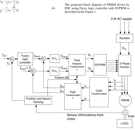
The proposed block diagram of PMSM driven by FOC using Fuzzy logic controller with SVPWM is described in the Figure 1.
Fuzzy logic controller
PI-iq
PI-id
Park Inverse
Transformatio n
SVPWM 3 Phase
Inverter
Park
Transformatio n
Clark
Transformation
Position and Speed
Sensing PMSM
Rectifier
3 Ф AC supply
ia
ib
Vα
Vβ
iα
iβ
Tref
Vdc
i
sdref = 0Vsqref
Vsdref
Tm
ic
(θ)
Sensor informations from motor
Position
i
Sdi
Sqi
Sqref [image:3.612.105.540.286.706.2]LOAD Shaft
ISSN: 1992-8645 www.jatit.org E-ISSN: 1817-3195
3. SPACE VECTOR PULSE WIDTH
MODULATION
The space vector PWM method is an advanced, computation-intensive PWM method which is the best among all the PWM techniques for variable-frequency drive applications. There are eight possible combinations for the switch commands which determine eight phase voltage configurations. This PWM technique approximates
the reference voltage Vref by a combination of the
eight switching patterns (V0 to V7) are described in
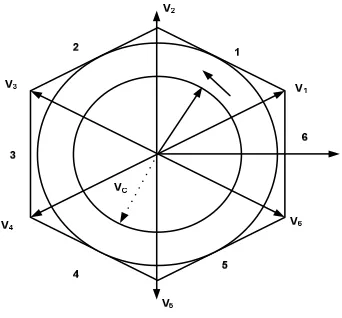
the Figure 2 with the Switching patterns and output voltages of a three-phase power inverter in Table 1. To implement the space vector PWM, the voltage equations in the abc reference frame can be transformed into the stationary αβ reference frame that consists of the horizontal (α) and vertical (β) axes, as a result, six non-zero vectors and two zero vectors are possible.
[image:4.612.228.399.215.374.2]Figure 2 Switching Vectors And Sectors
Table 1: Switching Patterns And Output Voltages Of A Three-Phase Power Inverter
Vector Va Vb Vc Vab Vbc Vca
V0={000} 0 0 0 0 0 0
V1={100} 2/3 −1/3 −1/3 1 0 -1
V2={110} 1/3 1/3 −2/3 0 1 -1
V3={010} − 1/3 2/3 −1/3 -1 1 0
V4={011} −2/3 1/3 1/3 -1 0 1
V5={001} − 1/3 −1/3 2/3 0 -1 1
V6={101} 1/3 − 2/3 1/3 1 -1 0
V7={111} 0 0 0 0 0 0
4. FUZZY LOGIC CONTROLLER (FLC) [1]
Fuzzy logic (FL) is defined as multi-valued logic which deals with problems that have fuzziness or vagueness.
Fuzzy logic is a methodology used for problem solving in any type of control system and it can be implemented in microprocessors, embedded microcontrollers, FPGA chips and PC based data acquisition and control systems. FL provides a trouble-free way to get at a definite conclusion based upon unclear, vague, inaccurate, noisy, or absent input information. Fuzzy Logic approach
towards a control system problem mimics how a person would make decisions.
NB NM NS Z PS PM PB
-2.2 -1.32 -0.88 -0.44 0 0.44 0.88 1.32 2.2
Figure 3 Inputs To FLC- Torque Error
NB NM NS Z PS PM PB
[image:5.612.84.524.70.650.2]-0.125-0.075 -0.05 -0.025 0 0.025 0.05 0.0750.125
Figure 4 Inputs to FLC- Change In Torque Error
NB NM NS Z PS PM PB
-2.2 -1.32 -0.88 -0.44 0 0.44 0.88 1.32 2.2
Figure 5 Torque Limit Output Of FLC
Table 2: Rules for FLC
e
∆e
B NM NS Z PS PM PB
NB NB NB NB NM NM NS Z
NM NB NB NB NM NS Z PS
NS NB NM NS NS Z PS PM
Z NM NM NS Z PS PM PM
PS NM NS Z PS PS PM PB
PM NS Z PS PM PM PB PB
PB Z PS PM PM PB PB PB
5. FIELD PROGRAMMABLE GATE ARRAY
Field Programmable Gate Array (FPGA) is low cost, performance DSP solution for high-volume, cost-conscious applications. Their efficiency in concurrent applications is achieved by using multiple parallel processing blocks. Due to parallel processing paths, different tasks do not want to compete for the same resources. In a single FPGA device multiple control loops can be executed at different rates. Because of parallel
processing the speed is very high. The FPGAs gives limitless flexibility to the designers due to reconfigurable option. It distributes memory throughout the device, so the dedicated memory needed by each task is permanently allocated. This provides a high degree of isolation between tasks. The designer of an FPGA controller has complete flexibility to select any combination of peripherals and controllers.
6. RESULTS AND DISCUSSION
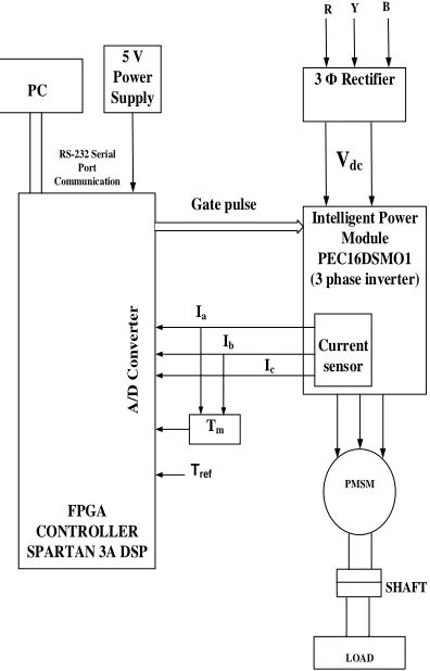
The simulation parameters of PMSM used in the simulink matlab and hardware are shown in table 3 with the Hardware block diagram and Hardware setup in Figure 6 and Figure 7. The Figure 8 and Figure 9 shows Inverter Line to line Voltage waveform and current waveform at 75% loading. The Figure 11 and Figure 12 shows Inverter Line to line Voltage waveform and current waveform at 100% loading. The Figure 10 and Figure 13 shows the torque waveform for 75% and 100% loading.
LOAD PMSM
Intelligent Power Module PEC16DSMO1 (3 phase inverter)
Current sensor
SHAFT
3 Ф Rectifier
R
FPGA CONTROLLER SPARTAN 3A DSP
A
/D
C
o
n
v
e
r
te
r
PC
5 V Power Supply
RS-232 Serial Port Communication
Ia
Ib
Ic
Gate pulse
Tref Tm
Y B
Vdc
[image:5.612.319.517.356.665.2]ISSN: 1992-8645 www.jatit.org E-ISSN: 1817-3195
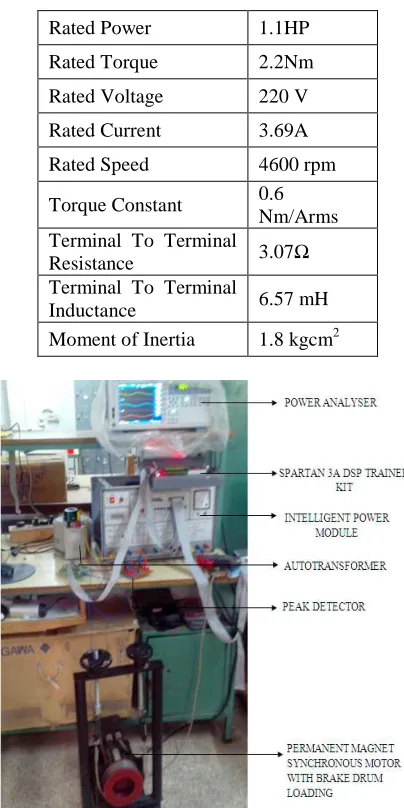
Table 3: Parameters Of PMSM
Rated Power 1.1HP
Rated Torque 2.2Nm
Rated Voltage 220 V
Rated Current 3.69A
Rated Speed 4600 rpm
Torque Constant 0.6
Nm/Arms Terminal To Terminal
Resistance 3.07Ω
Terminal To Terminal
Inductance 6.57 mH
[image:6.612.313.523.84.301.2]Moment of Inertia 1.8 kgcm2
Figure 7 Snapshot Of Hardware Setup
[image:6.612.90.292.110.514.2]6.1 Waveforms Of Inverter Line To Line Voltage, Current And Torque (75% Loading)
Figure 8 Inverter Line To Line Voltage Waveform For 75% Loading (X-Axis: Time In Ms: 1 Div= 10 Ms, Y-Axis (Vab, Vbc, Vca): Voltage In Volts: 1 Div= 325 V)
Figure 9 Current Waveform For 75% Loading (X-Axis: Time In Ms: 1 Div= 10 Ms, Y-Axis (Iab, Ibc, Ica):
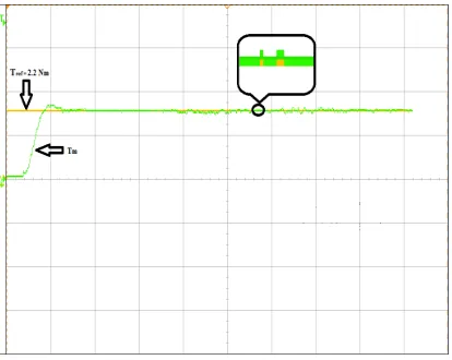
[image:6.612.316.523.357.556.2]Figure 10 Torque Waveform For 75% Loading(X-Axis: Time In S, 1 Div= 10s, Y-Axis: Torque In Nm, 1 Div=
2.2Nm)
Torque Ripple Factor(TRF%)
=
p e a k - p e a ka v e
1 0 0
T
T ×
(7)
[image:7.612.316.523.393.558.2]
From the Figure 10 the motor torque(Tm) follows the reference motor torque (Tref) with less torque ripples and it is shown in the circled portion of waveform which is zoomed and shown inside the figure 10. The torque ripple factor for the proposed scheme as per equation (7) is given below for figure 10.
Torque Ripple Factor (TRF %) =1.65 1.62 1.65
−
=1.81%
[image:7.612.91.299.500.649.2]6.2 Waveforms Of Inverter Line To Line Voltage, Current And Torque (100% Loading)
Figure 11 Inverter Line To Line Voltage Waveform For 100% Loading(X-Axis: Time In 1 Div= 10 Ms, Y-Axis:
Voltage In Volts: 1 Div= 325 V)
Figure 12 Current Waveform For 100% Loading(X-Axis: Time In Ms: 1 Div= 10 Ms, Y-Axis: Current In Amps(Iab,
Ibc, Ica): 1 Div= 3 A)
From the Figure 13 the motor torque(Tm) follows the reference motor torque (Tref) with less torque ripples and it is shown in the circled portion of waveform which is zoomed and shown inside the figure 13.
Figure 13 Torque Waveform For 100% Loading(X-Axis: Time In S, 1 Div= 10s, Y-Loading(X-Axis: Torque In Nm,
1 Div= 1.46 Nm)
The torque ripple factor for the proposed scheme as per equation (7) is given below for figure 13.
Torque Ripple Factor (TRF %) =2.24 2.2 2.2
−
ISSN: 1992-8645 www.jatit.org E-ISSN: 1817-3195
Table 4: Comparison Of Control Strategies In PMSM
CONTROL STRATEGIES TORQUE
RIPPLE (%)
Proposed FLC with SVPWM 1.81
P. Mattavelli, L.Tubiana, and M. Zigliotto,2005 [13]
3.8
W. Qian and K. Panda, 2004 [14] 3.9 M.Tarnik and J.Murgas, 2011 [20] 4
H. Hasanien, 2010 [19] 12
It is clear that variation in Torque shown in table 4 is less in case of Fuzzy logic controllers and they can achieve a minimum torque ripple than other control techniques. It has been viewed that the proposed control strategy has helped in reducing the torque ripples to 1.81%. Thus by using FLC based controller, ripples are reduced completely.
7. CONCLUSION
Fuzzy logic controller based Torque controller model of PMSM motor drive have been modeled and implemented using FPGA and the results have been presented to demonstrate the proposed FLC based control. The implemented hardware result of Fuzzy Logic Controller has shown that it is better over the PI Torque controller in reducing the torque ripples to 1.81%. And therefore it can be successfully used in position of PI Torque controller. In future implementation, Hybrid Neuro-Fuzzy controllers can be used to replace the PI controller.
ACKNOWLEDGEMENTS
We would like to thank the Management, Principal and Head of the EEE-PG Department of Sri Ramakrishna Engineering College for providing facilities and valuable support for carrying out this work.
REFERENCES
[1] B.Adhavan, M.S.Birundha, C.S.Ravichandran, and V.Jagannathan, “Torque ripple Reduction in Permanent Magnet Synchronous motor using Fuzzy logic control”, Australian
Journal of Basic and Applied Sciences,
Vol.7,No.7 May 2013, pp. 61-68.
[2] B.Adhavan, A.Kuppuswamy,G.Jayabaskaran, and V.Jagannathan,“Field oriented control of Permanent Magnet Synchronous Motor
(PMSM) using Fuzzy logic
controller”,Proceedings of International Conference on Recent Advances in Intelligent Computational Systems, Trivandrum, Kerala(India)
,
September 22- 24, 2011, pp.587-592.[3] J.C.Basilio and S.R.Matos,“Design of PI and PID controllers with transient performance specification”, IEEE Transactions on Education, Vol. 45, No. 4, August 2002,
pp.364-370.
[4] Bimal.K.Bose, “Modern Power Electronics and AC Drives”, PHI Learning Private Limited, Inc., 2005.
[5]F.Colamartino,C.Marchand, and A.Razek, “Torque ripple minimization in permanent magnet synchronous servo drive”, IEEE
Transactions on Energy Conversion, Vol. 14,
No. 3, September 1999, pp. 616-621.
[6]A.B.Dehkordi,A.M.Gole, and T.L.Maguire, “Permanent Magnet Synchronous Machine Model for Real- Time Simulation”,
Proceedings of International Conference on Power System Transients (IPST’05),
Montreal, Canada, June 19-23, 2005,pp.1-6.
[7] K.Gulez, A.A.Adam, and H.Pastaci, “Torque ripple and EMI noise minimization in PMSM using active filter topology and field oriented Control”, IEEE Transactions on Industrial
Electronics, Vol. 55, No. 1, January 2008, pp.
251-257.
[8]F.Heydari, A.Sheikholeslami, K.Gorgani Firouzjah, and G.Ardeshir,“Predictive Field Oriented Control of PMSM Using Fuzzy Logic”, Proceedings of 24thInternational Conference on power system, Tehran, Iran,
November 16-18. 2009, pp.1-10.
[9]T.M.Jahns, and W.L.Soong, “Pulsating torque minimization techniques for permanent magnet AC motor drives-a review”, IEEE
Transactions on Industrial Electronics, Vol.
43, No. 2, April 1996, pp.321-330.
[10] M.Kadjoudj, N.Golea, and M.E.H. Benbouzid, “Fuzzy Rule Based Model Reference Adaptive Control for PMSM Drives”, Serbian
Journal Electrical Engineering, Vol. 4, No. 1,
[11] R. Krishnan, “Permanent Magnet Synchronous and Brushless DC Motor Drives”, CRC Press, Inc., 2009.
[12] N.Li., X.Wei, and X.Feng, “An Improved DTC Algorithm for Reducing Torque Ripples of PMSM Based on Fuzzy Logic and SVM”,
Proceedings of International Conference Artificial Intelligence and Education (ICAIE),
Hangzhou,China, October 29-30, 2010, pp. 401-405.
[13] P.Mattavelli, L.Tubiana, and M.Zigliotto, “Torque-ripple reduction in PM synchronous motor drives using repetitive current control”,
IEEE Transactions Power Electronics, Vol.
20, No. 6, November 2005, pp. 1423–1431. [14] W.Qian, S.K. Panda and J.X.Xu, “Torque
ripple minimization in PM synchronous motors using Iterative learning control”, IEEE
Transactions on Power Electronics, Vol. 19,
No. 2, March 2004, pp 272-279.
[15] E.S.Sergaki, P.S.Georgilakis, A.G.Kladas, and G.S.Stavrakakis,“Fuzzy Logic Based Online Electromagnetic Loss Minimization of Permanent Magnet Synchronous Motor Drives”, Proceedings of 18th International
Conference Electrical
Machines,Vilamoura(Algarve),
Portugal,September 6-9, 2008, pp.1-7. [16] H.F.E. Soliman and M.E.Elbuluk,
“Improving the Torque Ripple in DTC of PMSM using Fuzzy Logic”, Proceedings of
Industrial Applications society annual meeting (IAS), Edmonton, AB, October 5-9,
2008,pp.1-8.
[17] Y. Sozer, D.A.Torrey, and S. Reva, “New inverter output filter topology for PWM motor drives”, IEEE Transactions on Power
Electronics, Vol. 15, No. 6, November 2000,
pp. 1007–1017.
[18] M.N.Uddin, “An Adaptive-Filter-Based Torque-Ripple Minimization of a Fuzzy-Logic Controller for Speed Control of IPM Motor Drives”, IEEE Transactions on
Industrial Applications, Vol. 47, No. 1,
February 2011, pp.350-358.
[19] H. Hasanien, “Torque ripple minimization of permanent magnet synchronous motor using digital observer controller”, Energy Conversion Management (Elsevier), Vol. 51,
No. 1, January 2010, pp. 98-104.
[20] M.Tarnik and J.Murgas, “Additional Adaptive Controller for Mutual Torque Ripple Minimization in PMSM Drive Systems”,
Proceedings of 18th IFAC World Congress,
Milano, Italy,Vol. 18, No. 1, January 2011, pp. 4119-4124.
[21] M. Saafan, Y. Haikal, F. Saraya, Fayez F.G. Areed, “Adaptive Control for Torque Ripple Minimization in PM Synchronous Motors”,
International Journal Computer Applications, Vol. 37, No. 5, January 2012,