STUDY ON CHARACTERISTICS BEHAVIOR OF DEVELOPING NOZZLE
FOR AEROSOL SPRAY
ASLINDA BINTI RAMLAN
A thesis submitted in
Fulfilment of the requirement for the award of the
Degree of Master of Mechanical Engineering
Faculty of Mechanical and Manufacturing Engineering
Universiti Tun Hussein Onn Malaysia
ABSTRACT
vi
ABSTRAK
CONTENTS
TITLE
i
DECLARATION
ii
DEDICATION
iii
ACKNOWLEDGEMENT
iv
ABSTRACT
v
ABSTRAK
vi
CONTENTS
vii
LIST OF FIGURES
x
LIST OF TABLE
xii
LIST OF SYMBOL
xiii
LIST OF APPENDICES
xv
CHAPTER 1
INTRODUCTION
1
1.1 Research Background
1
1.2 Aerosol Spray
2
1.2.1 History of the Aerosol
3
1.2.2 Alternative Aerosol Propellants
3
1.2.3 How an Aerosol Works
4
1.2.4 Household Aerosol Spray
4
1.2.5 Household Aerosol Production
5
1.3 Problem Statement
5
1.4 Research Objective
7
1.5 Scopes of Study
7
viii
CHAPTER 2
LITERATURE REVIEW
9
2.1 Introduction
9
2.2 Spray Characteristics
10
2.2.1 Droplet Size Distribution
11
2.2.2 Mean Drop Size
13
2.2.3 Cone Angle
13
2.2.4 Penetration
13
2.3 Atomisation
14
2.3.1 Surface Tension
14
2.3.2 Viscosity
15
2.3.3 Density
15
2.4 Atomiser
16
2.4.1 Atomiser Requirement
16
2.4.1 Type of Atomizer
16
2.5 Effervescent Atomisation
18
2.6 Internal Nozzle Cavitations
18
2.7 Problems in Reduction of VOC
19
2.8 Nozzle Design in Reduction of VOC
23
CHAPTER 3
METHODOLOGY
27
3.1 Introduction
27
3.2 Flow Chart of Research
28
3.3 Measurement Works
29
3.4 Simulation Works
30
3.4.1 Computational Fluid Dynamics
30
3.4.2 ANSYS CFX
31
3.4.2.1 Steps in ANSYS CFX
31
3.4.3 Numerical Method
39
3.4.4 Turbulence Models
41
3.4.4.1 RNG
k-
ε Model
41
CHAPTER 4
RESULTS AND DISCUSSION
45
4.1 Introduction
45
4.2 Simulation Validation
45
4.3 Plain Nozzle
47
4.3.1 Effect of Flow with Various Pressure in
Isosurface Perspective
47
4.3.2 Effect of Velocity for n-butane and Water
with Various Pressure at Exit Nozzle
52
4.3.3 Effect of TKE for n-butane and Water
with Various Pressure at Exit Nozzle
55
4.3.4 Effect of Reynolds Number for n-butane
and Water Liquid Phases
58
4.3.5 Summary of Plain Nozzle
61
4.4 Swirl Nozzle
63
4.4.1 Effect of Flow with Various Pressure in
Isosurface Perspective
63
4.4.2 Effect of Velocity for n-butane and Water
with Various Pressure at Exit Swirl
Nozzle
68
4.4.3 Effect of TKE for n-butane and Water
with Various Pressure at Exit Swirl
Nozzle
71
4.4.4 Effect of Reynolds Number for n-butane
and Water Liquid Phases
74
4.4.5 Summary of Swirl Nozzle
77
CHAPTER 5
CONCLUSION AND RECOMMENDATIONS
79
5.1 Conclusion
79
5.2 Recommendations
80
REFERENCES
81
x
LIST OF FIGURES
FIGURE
TITLE
PAGE
1.1
Typical household aerosol sprays, from left to right: air
freshener, body spray and insecticide spray
5
2.1
Aerosol cans
9
2.2
Generic aerosol can, courtesy British Aerosol Manufacturers
Society
10
2.3
Drop Size Basics
12
2.4
Classification of Nozzle Relative to Droplet Size Categories
12
2.5
Viscosity, droplet size, and when atomization occurs
15
2.6
Actuator with Simple Orifice
17
2.7
Energy sources for flashing propellant
19
2.8
Flow Schematic of Atomisation Flow Visualisation of Improved
Atomising Nozzle (A) & Photograph of Spray Plume (B)
23
2.9
Selection of the different throttle and exit stages
26
2.10
Throttles and Exit Models
26
3.1
Research Flow Chart
28
3.2
Vertical Profile Projector
30
3.3
Working Directory
31
3.4
Plain nozzle design
32
3.5
Swirl nozzle design
33
3.6
Plain nozzle design meshing
34
3.7
Swirl nozzle design meshing
35
3.8
Boundary Condition
37
4.1
The design of exit nozzle
45
4.5
Turbulence kinetic energy (TKE) of plain nozzle at various
pressures
56
4.6
TKE versus pressure for n-butane and water at exit nozzle
57
4.7
Reynolds Number of plain nozzle for 3 regions at various
pressures
59
4.8
Reynolds Number versus pressure for n-butane and water liquid
phase
60
4.9
Isosurface of swirl nozzle at various pressures
67
4.10
Velocity contour of swirl nozzle at various pressures
69
4.11
Velocity versus pressure for n-butane and water at exit swirl
nozzle
70
4.12
TKE of swirl nozzle at various pressures
72
4.13
TKE versus pressure for n-butane and water at exit swirl nozzle
73
4.14
Reynolds Number of swirl nozzle for 3 regions at various
pressures
75
xii
LIST OF TABLES
TABLE
TITLE
PAGE
2.1
Surface Tension of Familiar Liquids
14
2.2
Summary of Current Aerosol Products
21
2.3
Design and Description
25
3.1
Main Unit Specifications of Profile Projector
29
3.2
Meshing report for plain nozzle
34
3.3
Meshing report for swirl nozzle
35
3.4
Material Properties
36
3.5
Boundary Condition
37
3.6
RNG model coefficients
42
4.1
Summaries of results
46
4.2
Summarised of the velocity and TKE for plain nozzle
61
4.3
Summarized of the Reynolds Number for plain nozzle by
each region
61
4.4
Increments of Reynolds Number for both liquid phases
62
4.5
Summarised of the velocity and TKE for swirl nozzle
77
4.6
Summarized of the Reynolds Number for swirl nozzle by
each region
77
LIST OF SYMBOL
VOC
-
Volatile Organic Compounds
CFD
-
Computational Fluid Dynamics
CFCs
-
Chlorofluorocarbons
HCs
-
Hydrocarbons
PVC
-
Precision Valve Corporation
DME
-
Dimethylether
CO
2-
Carbon Dioxide
N
2 -Nitrogen Dioxide
CSPA
-
Consumer Specialty Products Association
U.S.
-
United State
GLR
-
Gas/liquid Mass Ratio
DSD
-
Droplet Size Distribution
VMD
-
Volume Median Diameter
TKE
-
Turbulence Kinetic Energy
RNG
-
Renormalisation Group
I.C.
-
Internal Combustion
EU
-
Europe
N/m
-
Newton per Meter
ρ
-
Density
P
-
Pressure
T
-
Temperature
xiv
v
-
Velocity
p
-
Static Pressure
g
-
Gravitational Force
F
-
Other Forces
τ
-
Stress Tensor
μ
-
Viscosity
I
-
Unit tensor
ε
-
Turbulent Dissipation
ω
-
Turbulent Specific Dissipation
ζ
-
Ratio of the Turbulent to Mean Strain Time Scale
σ
k-
Turbulent Schmidt Number
L
-
Turbulent Length Scale
m
-
Mass Flow Rate
A
-
Area
LIST OF APPENDICES
APPENDIX
TITLE
PAGE
1
Design of Exit Plain Nozzle (Simple Orifice)
83
2
Design of Exit Swirl Nozzle
84
3
Gantt Chart of Mater’s Project 1
85
CHAPTER 1
INTRODUCTION
1.1
Research Background
Sprays are used in several applications, such as in industrial, agricultural, domestic
and many other applications. One of the largest markets use form of spray technology is the
household aerosol including personal care product. It was design in a presurized canister.
These include anti-perspirants, air freshner, perfumes, deo-dorant and hair spray that are
commonly used all over the world. It has been commerciallised due to the useful system
which is easy and ready to use. It is convenient, effective and efficient spray.
Consumer used aerosol spray as a household product every day and not all of us
noted this spray is containing volatile organic compounds (VOC) that contributes to
formation of tropospheric ozone [1-2]. VOC is a large group of Carbon-based chemicals
which is easy to avaporate at room temperature. It has a potential can cause health effect
depending on the time exposure.
To avoid this situation become critical, nowadays a lot of manufacturers are focus to
develop some kind of water based aerosol product. However the contents are still used
aerosol more than water. Based on a few research found that, the performance of aerosol
safe our environment in the future, an improvement of the product design should take an
action.
The fields of household aerosols have a marked commonalty with their needs to
produce fine sprays using portable devices. These devices generally are designed as atomiser
or nozzles and it has been developed in a wide range of the different applications. The
success of a spray job is depending on the product chosen, application timing and correct
operation of the spray equipment. However, for the effective spraying the most important are
the correct nozzle selection, speed and pressure. The behavior of the spray aerosol is
analysed through simulation to make an improvement for the new future design spray that
not only has same characteristic with existing product but also friendly to the environmental.
1.2
Aerosol Spray
Aerosol is a fine particles of liquid or solid subtances in air which contained three
element of dispensing system such as active ingredients (soap or disinfectant), inert or
inactive ingredients (water) and propellant. The propellant is a gaseous compound which
pushes the product out of the container and produces a spray or foam. A spray is generated
when a fluid is caused to flow through a nozzle arrangement under pressure. In most cases,
the propellant also acts as a solvent to keep the product at the proper strength.
Formerly, the first aerosol spray used chlorofluorocarbons (CFCs) as a propellant
until scientist observe that it utilize will damage the Earth’s ozone layer. Therefore, in 1978,
the use of CFCs is strictly banned especially in the United States then follows by others
countries such as Canada, Mexico, Australian and many European nations. Awareness
among the countries, drag others developing countries took place avoid to use CFCs. Today
a variety of different propellants are used in aerosol cans to replace CFCs, where liquefied
petroleum gas being among the most popular. In the United States, the most common
3
1.2.1 History of the Aerosol
The first use for an aerosol package arose during World War II but, the idea of using
low-pressure liquefied gas to atomise droplets of liquid in the air was developed in 1924.
Canisters filled with insecticide and propellants were used to protect U.S. servicemen from
insects carrying diseases such as malaria. Shortly after the war, Robert Abplanalp, founder of
Precision Valve Corporation (PVC), invented the first mass-produced aerosol valve. Then,
the patent was filed in September 1949 and was issued on March 17, 1953. From that
invention, the aerosol industry quickly developed in the United States and around the world.
1.2.2 Alternative Aerosol Propellants
Typically, there are four main alternative types of propellant such as:
• Hydrocarbons (HCs)
• Dimethyl ether (DME)
• Compressed gases (e.g. CO2, N2, compressed air, nitrous oxide)
• HFCs
HCs have established a dominant position in the aerosol market. The HCs used are
usually mixtures of propane, butane and iso-butane. The mixture proportions are chosen to
provide the appropriate vapour pressure. HCs are effective and cheap propellants. The main
disadvantages are flammability and VOC emissions. Manufacturers have managed to
1.2.3 How an Aerosol Works
An aerosol package is an air-tight, pressurised container that including the three
main elements mention before. All of these pieces work together based on simple scientific
principles. Just pressing the actuator button, the aerosol spray will function and due to that
pressing effect, the valve will open. Since the pressure outside the can is less than the
pressure inside, the propellant expands, pushing the product up the dip tube and out through
the valve to nozzle. The nozzle itself is constructed such that to ensure it atomise the product
as it is sprayed out making tiny little drops. This system allows the product to be applied in a
variety of way such as in a fine mist; a metered spray delivering just the right amount, foam,
or even a long distance spray.
1.2.4 Household Aerosol Spray
The pressurised household aerosol can is found universally in the developed world
and in most homes in the developing world. The expression “household aerosol” is used to
describe pressurised cans for household purposes such as cleaning, polishing, disinfectant
etc., and include the used term “personal care” area, i.e. deodorants, hair sprays etc.
Furthermore the use of these devices extends into other areas, such as for lubrication, paint
application and de-icing of vehicles. Figure 1.1 shows a typical aerosol cans which is
pressurised, typically to 4 to 5 bar, using a liquefied gas. That is, the propellant is a low
5
[image:17.595.150.473.73.197.2]
Figure 1.1: Typical household aerosol sprays, from left to right: air freshener, body spray
and insecticide spray [5]
1.2.5 Household Aerosol Production
Aerosol Pressurised Products Survey by Consumer Specialty Products Association
(CSPA) has revealed 2010 as the highest year ever for U.S. aerosol production. The
estimated total units filled in 2010 were 3.745 billion, which establishes the historical high
for fillings in the United States. Household and personal care products rank as the two
highest production product categories, with household products reporting a 9.2% increase in
2010 over 2009 [6].
1.3
Problem Statement
Aerosols improve our quality of life in many ways. They provide benefits in medical
treatment, health care, pest control, disease prevention, personal care and hygiene,
household, automotive and industrial cleaning maintenance. However, there are three main
problems with pressurised aerosol spray, which are the production of VOC, the use of oil
based energy and the danger of explosion after disposal because of flammability [7].
Besides, the protection of the environment has become a European key issue since the early
90s. Legislation controlling VOC use is becoming incresingly strict and is already affecting
Therefore, a new generation of aerosol technology are expand rapidly where the
research and development are focused on the analysis of propellants, packaging and
ingredients to make the aerosol has a high performance product. Currently market interest is
looking towards reducing the amounts of propellant or by replacing it completely with a
lower cost and more environmentally friendly means of creating the spray. [3].
This study is focus on investigation of internal nozzle geometries for the aerosol
spray by CFD modeling. Design from previous study and combination with the conventional
nozzle is chosen to analyse since nozzle design is one of the characteristic to ensure the
efficient of spraying. Besides, to reduce the VOC content of existing aerosol can, water is
used to replace the propellant. However, this application will produce poor atomisation of
the spray. Hence, the flow of spraying product is analysed by implement the high turbulence
flow where high turbulence flow can resolve the atomisation problem. Then, based on that,
further prediction for the nozzle design of fine spray which can control in liquid viscosity
7
1.4
Research Objective
This research focused on the simulation of flow for conventional household aerosol
nozzle for future developing nozzle design. Here, the characteristic of the flow is determined
by Computational Fluid Dynamics (CFDs). The main purposes of the research are:
1.
To analyse internal nozzle geometries at atomiser exit(s) for single liquid
phases.
2.
To extend the above analysis of the internal nozzle geometries that produces
conditions for dissolved gas release for further prediction.
3.
To predict turbulence kinetic energy.
1.5
Scopes of Study
In order to achieve the goal of this research, the analysis preferred to uses ANSYS
software; CFX version 14 as a design tool due to the trusted and proven software for
simulation of fluid flows. Besides, the analysis is focused on the turbulence flow with
1.6
Thesis Outline
To accomplish this study, simulation by ANSYS CFX will carried out based on
chosen nozzle design. Through this analysis, the volume of the thesis is divided into five
chapters. The outlines of each chapter are as follows:
Chapter 1 expresses the introduction of aerosol spray, it history, production
and little bit about operation. A brief explanation regarding the concern of
aerosol content and it application also described. Then the detail about
objectives and scope of this study are determined.
Chapter 2 consists of literature reviews on spray characteristic by a few
researchers. The topics in the literature are related in order to analyse the
characteristic of the spray.
Chapter 3 explains the method to achieve the study. These are including the
way to construct the design, equation involve and simulation process.
Chapter 4 discusses the result from the simulation. Comparisons data are
explain for further prediction and better future development design.
CHAPTER 2
LITERATURE REVIEW
2.1
Introduction
A spray is a collection of moving droplets that usually are the result of atomisation
and it moving in a controlled fashion. Atomisation refers to the process of breaking up bulk
liquid into droplet, often occurs after the liquid passes through a nozzle. The type of nozzle
selected is depending on the application of the spray and it will determine the effectiveness
of the spray. Therefore understanding in spray characteristics is essential to select and
develop the optimal nozzle. The details construction of the aerosol can as shown in Figure
2.1. Moreover, Figure 2.2 show the typical aerosol can were the actuators is that part that fits
on the valve. Most actuators are in two parts, the main body and the exit orifice insert as a
Figure 2.1: Aerosol can [5]
Figure 2.2: Generic aerosol can, courtesy British Aerosol Manufacturers Society [4]
2.2
Spray Characteristics
Spray characteristics were quantified in terms of spray properties such as drop size
distribution, mean drop size, cone angle and penetration. It is analysed in terms of the
gas/liquid mass ratio (GLR) [8]. The spray characteristics were investigated to determine the
optimum aerosol spray while considering volatile organic carbon (VOC) reduction. An
optimal effective aerosol spray nozzle can be developed by measuring the spray
[image:22.595.219.469.278.502.2]11
efficiency. Thus, it shows that evaluated the spray characteristics near the nozzle is the most
important parameter when developing aerosol sprays [7].
2.2.1 Drop Size Distribution
The droplet size distribution (DSD) in sprays is the crucial parameter needed for the
fundamental analysis of the transport of mass, momentum and heat in engineering systems.
Moreover, the DSD determines the quality of the spray and consequently influences to a
significant extent the processes of fouling and undesired emissions in aerosol spray.
According to R.A Sharief [3], the size of the aerosol droplets produced by
conventional nozzle arrangements is dictated by a number of factors, including the
dimensions of the outlet orifice and the pressure with which the fluid is forced through the
nozzle. However, problems can arise if it is desired to produce a spray that comprises small
droplets with a narrow droplet size distribution, particularly at a low pressure. It happened
especially when fluids contains in the can reduced or depleted levels of propellant, or a
relatively low-pressure propellant such as compressed gas or a low pressure systems is used.
He analysed that, the problem of providing a high quality spray at low pressures is further
exacerbated if the fluid used has a high viscosity because it becomes harder to atomise the
fluid into sufficiently small droplets.
Figure2.3 shows the guidelines for spray nozzle selection, where:
Air atomizing nozzles produce the smallest drop sizes followed by fine spray,
hollow cone, flat fan and full cone nozzles
Higher pressures yield smaller drops and lower pressures yield larger drops
Lower flow nozzles produce the smallest drops and higher flow nozzles
produce the largest drops
Increases in surface tension will increase drop size
Drop velocity is dependent on drop size. Where:
o
Small drops may have a higher initial velocity, but velocity
diminishes quickly.
Figure2.3: Drop Size Basics [9]
The range of drop sizes for aerosols spray is less than 100 microns which is fall in
fine spray. Figure 2.4 shows the graph for classification of the test nozzle relative to droplet
size by categories. Droplets smaller than 100 microns in size is obtain a horizontal trajectory
[image:24.595.119.561.73.218.2]in a very short time and evaporate very rapidly.
Figure 2.4: Classification of Nozzle Relative to Droplet Size Categories [10]
[image:24.595.151.515.404.650.2]13
The quality or fineness of an atomisation process is usually described in terms of a
mean drop size. The most widely used is the Sauter mean diameter which represents the
volume/surface ratio of the spray [11]. The volume median diameter (VMD or Dv0.5) is
commonly used to characterize droplet size spectra. VMD is the droplet size (in microns) at
which half of the spray volume is composed of larger droplets and half the spray of smaller
droplets [10].
2.2.3 Cone angle
The cone angle is often given by as the angle formed by two straight lines drawn
from the discharge orifice to cut the spray contours at some specified distance from the
atomiser face [11].
2.2.4 Penetration
The penetration of a spray may be defined as the maximum distance it reaches when
injected into stagnant air. It is governed by the relative magnitudes of two opposing forces;
the kinetic energy of the initial liquid jet and the aerodynamic resistance of the surrounding
gas [11]. Turbulence models had pronounced effects on vapor penetration while effect on
liquid spray penetration was negligible. The best vapor penetration results were predicted by
the RNG k-ε model using CONVERGE and realizable k-ε model using OpenFOAM.
2.3
Atomisation
The atomisation process is essentially one in which bulk liquid is converted into
small drops. Basically it can be considered as a disruption of the consolidating influence of
surface tension by the action of internal and external forces. Surface tension is the property
of a liquid that causes droplets and soap bubbles to pull together in a spherical form and
resist spreading out. This property causes sheets or thin ligaments of liquid to be unstable;
that is, they break up into droplets, or atomise. Besides surface tension, the viscosity and
2.3.1 Surface Tension
Surface tension tends to stabilize a fluid, preventing its breakup into smaller
droplets. Everything else being equal, fluids with higher surface tensions tend to have a
larger average droplet size upon atomisation. Table 2.1 lists a number of common materials
[image:26.595.151.513.219.422.2]and their surface tensions.
Table 2.1: Surface Tension of Familiar Liquids [12]
Surface Tension of Common Fluids
Liquid Surface Tension (N/m @20C)
Ethyl alcohol 0.022
Soapy water 0.025
Benzene 0.029
Olive Oil 0.032
Lubricating oil 0.037
Glycerine 0.063
Water 0.073
15
2.3.2 Viscosity
A fluid’s viscosityhas a similar effect on droplet size as surface tension. Viscosity
causes the fluid to resist agitation, tending to prevent its breakup and leading to a larger
average droplet size. Figure 2.5 represents the relationship among viscosity, droplet size, and
[image:27.595.247.393.218.469.2]when atomisation occurs.
Figure 2.5: Viscosity, droplet size, and when atomisation occurs [12]
2.3.3 Density
Densitycauses a fluid to resist acceleration. Similar to the properties of both surface
2.4
Atomiser
Numerous devices to generate spray flows have been developed and they are
generally designed as atomisers or nozzles [13]. An atomiser is a device which converts a
stream of liquid into a fine spray. The experiments carried out by R.A Sharief & G. Eales
proved that, flow control devices permit control of droplet size, control of flow rate, spray
pattern manipulation, the production of narrower droplet size distributions and reduction of
can VOC content.
2.4.1 Atomiser Requirement
An ideal atomiser would posses all the following characteristics:
a)
Ability to provide good atomisation over a wide range of liquid flow rates.
b)
Rapid response to changes in liquid flow rate.
c)
Freedom from flow instabilities.
d)
Low power requirements.
e)
Capability for scaling to provide design flexibility.
f)
Low cost, light weight.
g)
Low susceptibility to damage during manufacture and installation.
h)
Low susceptibility to blockage by contaminants.
i)
Uniform radial and circumferential spray distribution.
2.4.2 Type of atomiser
The type of atomiser is depending on the spray application. Most commonly atomiser used
in industrial are as follows:
a)
Plain-orifice atomiser
The plain orifice may operate in single phase or cavitating flow regime. It is a
simple circular orifice that is used to inject a round jet of liquid into the
surrounding air. Finest atomisation is achieved with small orifices but in
practice the difficulty of keeping liquids free from foreign particles usually
limits the minimum orifice size to around 0.3mm.
17
b)
Pressure-swirl Atomiser
[image:29.595.173.505.241.408.2]A circular outlet orifice is preceded by swirl chamber into which liquids
flows through a number of tangential holes or slots. The swirling liquid
creates a core of air or gas that extends from the discharge orifice to the rear
of the swirl chamber. The liquid emerges from the discharge orifice as an
annular sheet, which spreads radially outward to form a hollow conical spray.
Figure 2.6: Actuator with Simple Orifice [4]
c)
Effervescent flow atomizer
2.5
Effervescent Atomisation
Effervescent atomisation is a method of twin-fluid atomisation that involves
bubbling a small amount of gas into the liquid before it is ejected from the atomiser.
Effervescent atomisation has been used successfully in a number of applications since its
inception over ten years ago. It has been well studied during this period, and the published
literature includes experimental and analytical investigations of both atomiser performance
and the fundamental mechanisms involved in the atomisation process.
The literature also includes application-oriented studies that report the development
of effervescent atomisers for gas turbine combustors, consumer products, furnaces and
boilers, I.C. engines, and incinerators. Through these studies a fair appreciation of the
capabilities of the technique has been achieved. Continuing work is aimed at exploring the
use of effervescent atomisation in new areas, as well as acquiring a better understanding of
current applications. More in-depth studies are also in progress on the various basic
mechanisms that contribute to the overall atomisation process.
2.6
Internal Nozzle Cavitations
The study of the internal nozzle flow includes turbulence, developing pipe flow, and
cavitations. Cavitations phenomenon can be defined as the formation of vapor bubbles in a
fluid [15]. The generation of the cavitations was affected by the shape and dimension of the
19
Figure 2.7: Energy sources for flashing propellant [4]
Figure 2.7 indicates bubbles in the dip tube and the actuator including nozzle. This is
inevitable because the pressure drops with the flow along the tube, through the valve and
around the bend in the actuator and nozzle: every drop in pressure changes more of the
propellant into the gas phase. An inevitable result of this pressure drop and phase change is
that heat is removed to provide the latent heat and this heat comes from the liquid and also
the actuator. Thus aerosol cans and their sprays are always cool to the touch when spraying.
This cooling action may be important when the sprayed formulation contains oils, such as
silicone oil found in antiperspirants: these oils will increase in viscosity and may thus result
in larger droplets [4].
2.7
Problems in Reduction of VOC
The reduction of VOC leads to two major problems, plus a range of ancillary
difficulties related to these problems [4].
These major problems are:
(1)
Reduction of VOC inevitably means using less flashing propellant:
this gives greater demands on achieving good atomisation efficiency. There is
also a marketing reason for such replacement: the customer may resist
purchasing products that do not appear to have much liquid in the can.
(2) The can contents of ethanol and certain solvents will need removal or reduction.
Ethanol is the main carrier fluid for many important applications. The problems
caused by replacing it with water, which appears to be inevitable as there are no
other replacements that are not targeted by legislation, have been described already.
The summary of current aerosol products by previous study is shown on Table 2.2. It
provides the present main formats of pressurised aerosols including typical current spray
21
Table 2.2: Summary of Current Aerosol Products [4]
Product Category CARB VOC limit Current Products (Europe) Typical Current Spray Characteristics Problems
Hair spray 55% European formulations
80% - 90% VOC (+),
butane/propane, polymer
in ethanol. European
moves to restrict VOCs.
Also DME or
DME/butane at 30%
propellant; 50% alcohol
and 15% water.
Vol Med Dia. 50-80
Microns spray angle
30 degrees
(+), hollow cone.
Flow rate 0.3 to
1.2g/sec.
Require good atomisation,
negatively affected by
viscosity increase with water
addition. Fast drying rate
negatively affected by water
and increased droplet size.
Products must wet out hair
effectively.
Air
fresheners
Progressiv
e-ly,
30% to
18%
(liquid/
pump
sprays)
Typically around 30%
butane 68% water, plus
fragrance, and emulsifier.
Simple orifices common.
Vol. Med Dia. 30 to
45 microns.
Flow rate 0.8g/s.
30 degree full cone.
1.5m minimum
throw
(penetration)
Finer sprays preferred, but
must have adequate
penetration (throw), difficult
to get finer than 30-40 micron
with aqueous formulation.
Larger particle sizes rapidly
settle, taking fragrance with
them. Anti-perspirants HVOC 40% and MVOC 10%
Simple orifice with
“bullnose” & VPT.
Typ.composition: silicones 13%, hydrocarbon propellant 75%, Aluminium chlorohydrate powder 10%.
Vol Med Dia 10-
20 microns.
Flowrate 0.75-1g/s.
Spray angle 20-
30degrees full cone.
Interest in reducing inhalable
fraction (sub-7 microns say)
currently 20%+. Particulates +
silicone = high viscosity:
Non flashing spray would be
coarse. Cool feel attractive to
customer. Personal Deodorants HVOC 0% and MVOC 10% Powder-free often
essentially 97% VOC:
50% ethanol plus
propellant plus perfume
etc. MBU (Swirl) insert
common.
Vol Med Dia up to
40 microns.
Flowrate 0.6g/s.
Spray angle up to 40
degrees, full or
hollow cone.
Replacing ethanol with water
Spray Paints 88% but reducing Hydrocarbon and/or DME propellant.
Typically acrylic resins
plus solvent. Solids
10-15%, HC 25-30% solvent
55%. MBU (Swirl) insert,
or fan jets.
Ideally Vol Med Dia
40-50 micron.
Flowrate 1g/s (+)
Spray angle wide
rages used.
Water based products for low
VOC have drop size
challenges. Narrow size
distribution ideal: less than 30
microns = drift, greater than
60 microns = runs.
Insecticide crawling bug 15%. flying bug 25% Hydrocarbon propelled,
aqueous or solvent
formulation. MBU or
simple orifice, with
VPT.
For flying insects
Vol Med Dia 30-40
microns. Flowrate
0.5-1.0g/s (+). For
crawling insects
larger
droplets and narrow
coverage, 1-2.5 g/s
Good penetration with no “fall out” of large drops plus low
inhalable fraction: low VOC
aqueous formulations have
difficulty in achieving this.
Furniture Polish 25% (01/01/94) 17% (31/12/04)
Butane propellant, water,
butane and solvent,
usually MBU insert.
Compressed air-driven
systems: wax, solvent,
surfactant, water: MBU
Vol Med Dia 110 (HC
propellant) to 150
microns (+) compressed
gas. Flowrate 1.5 g/s (+)
Spray angle 30 to 90
degrees
Vol Med Dia 110
(HC propellant) to
150 microns
(+) compressed gas.
Flowrate 1.5 g/s (+)
Spray angle 30 to 90
degrees hollow cone.
Wax-water solution is viscous
and non- Newtonian,
problems with reduced
23
2.8
Nozzle Design in Reduction of VOC
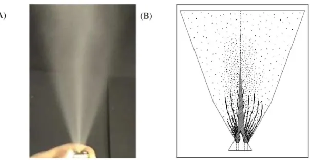
[image:35.595.171.473.434.590.2]From the experiments carried out by Raj designs on reduced VOC hair spray,
its designs has proven that great improvements on reduction of drop sizes and crucial
reduction on inhalable by keeping the flow rate the same with comparison to the
original cap. More advanced designs of actuators have been made depending on the
inventions related to shape chambers, multiple passages of flow and throttles. The
flow of improve atomisation produces is illustrated in Figure 2.8. It is now possible
to manufacture household can aerosols such as air fresheners, body sprays and hair
sprays with massive reduction in hydrocarbons or volatile organic compounds
(VOC). Also some of these designs can help to atomise viscous fluids such as oil,
polish and paint. Also these designs can work with compress gas can products. From
the experiments carried out it is obvious that these designs helped several products
which was rather difficult not a long time ago. It is also helped to reduce the
inhalable of these cans especially with the anti-perspirant, oil and paint [3].
Figure 2.8: Flow Schematic of Atomisation
Flow Visualization of Improved Atomizing Nozzle (A) &
Based on the further development in actuator design and investigation into domestic
household aerosols studied by R.A Sharief, the new nozzle design can be predicted using his
design because nowadays, it is possible to incorporate a wide range of flow control devices
and orifice designs into a single injection moulded part. Since a new injection moulding
technique allows the actuator and exit orifice to be made as one part [16].
The designs that studies by author are illustrated in Figure 2.9, where the selection of
the different throttle and exit stages that have been tested for different products. The
description of the design has been used is shown in Table 2.3. While, Figure 2.10 shows
80
References
[1] W. H. Lamason (1981), "Technical discussion of per capita emission factors for
several area sources of volatile organic compounds".
[2] N. Ostojic (1996), "End use of solvents containing volatile organic compounds,".
[3] R. A. Sharief (2009), "Further developments in actuator designs for flashing
household aerosol-hair spray," presented at the International conference on liquid
atomisation and spray systems, Vail, Colorado.
[4] A. J. Yule (2006) , "The household aerosol: present and future of the world’s largest
market for spray technology," presented at the 10th International Conference on
Liquid Atomisation and Spray Systems, Kyoto, Japan.
[5] T. V. Wilson. (2011), "How silly string works"
Available: http://entertainment.howstuffworks.com/silly-string1.htm
[6] Linda Group (2011). Aerosol europe.
Available:
www.aerosoleurope.de/2011/10/cspa-reports-history-high-for-u-s-production-of-aerosol-products
[7] Yuji Ikeda, et al. (2006), "An aerosol nozzle that improves the spray agglomerative
characteristics for optimal insecticide delivery to the target," presented at the
International Conference on Liquid Atomisation and Spray Systems, Kyoto, Japan.
[8] D. Loebker and H. J. Empie (1998), "Effervescent spraying of a medium to high
viscosity newtonian liquid at high mass flowrate," Atlanta, Georgia.
[9] Spraying System Co. (2010), " Guideline for spray nozzle selection. Available:
www.spray.com
[10] M. I. Jahirul, et al. (2010), "Comparative engine performance and emission analysis
of CNG and gasoline in a retrofitted car engine," Applied Thermal Engineering, vol.
30, pp. 2219-2226.
[11] A. H. Lefebvre (1989), "Atomisation and sprays". West Lafayette, Indiana, Taylor &
Francis.
[12] Graco (2011), "Atomisation, Concept and training".
Available: www.graco.com
[13] X. Jiang, et al. (2010), "Physical modelling and advanced simulations of gas–liquid
two-phase jet flows in atomisation and sprays," Progress in Energy and Combustion
Science, vol. 36, pp. 131-167.
[14] J.Jedelsky, et al. (2003), "Characterization of spray generated by multihole
9th International Conference on Liquid Atomisation and Spray Systems, Sorrento,
Itali.
[15] D. P. Schmidt (1997), "Cavitation in diesel fuel injector nozzles," Doctor of
Philosophy, Mechanical Engineering, University of Wisconsis-Madison.
[16] R. A. Sharief (2010), "Investigation into domestic household aerosol air freshener
and body spray," presented at the 23rd Annual Conference on Liquid Atomisation
and Spray Systems, Brno, Czech Republic.
[17] Rok Šibanc, et al. (2010) , "Process Modelling: Use of computational fluid dynamics
for analysis of pharmaceutical equipment".
Available: www.glatt.com
[18] R. H. Nichols (2010), "Turbulence models and their application to complex flows",
University of Alabama at Birmingham.
[19] C. Baumgarten (2006), “Mixture formation in internal combustion engines”,

![Figure 2.1: Aerosol can [5]](https://thumb-us.123doks.com/thumbv2/123dok_us/8777503.902287/22.595.219.469.278.502/figure-aerosol-can.webp)
![Figure 2.3: Drop Size Basics [9]](https://thumb-us.123doks.com/thumbv2/123dok_us/8777503.902287/24.595.151.515.404.650/figure-drop-size-basics.webp)
![Table 2.1: Surface Tension of Familiar Liquids [12]](https://thumb-us.123doks.com/thumbv2/123dok_us/8777503.902287/26.595.151.513.219.422/table-surface-tension-of-familiar-liquids.webp)
![Figure 2.5: Viscosity, droplet size, and when atomisation occurs [12]](https://thumb-us.123doks.com/thumbv2/123dok_us/8777503.902287/27.595.247.393.218.469/figure-viscosity-droplet-size-atomisation-occurs.webp)
![Figure 2.6: Actuator with Simple Orifice [4]](https://thumb-us.123doks.com/thumbv2/123dok_us/8777503.902287/29.595.173.505.241.408/figure-actuator-with-simple-orifice.webp)
![Figure 2.7: Energy sources for flashing propellant [4]](https://thumb-us.123doks.com/thumbv2/123dok_us/8777503.902287/31.595.201.440.74.229/figure-energy-sources-flashing-propellant.webp)
![Table 2.2: Summary of Current Aerosol Products [4]](https://thumb-us.123doks.com/thumbv2/123dok_us/8777503.902287/33.595.89.573.105.760/table-summary-of-current-aerosol-products.webp)