Modelling and Simulation for Used Genetic Algorithm
Method to Speed Control of Three-phase Induction Motor
Joko Kusnandi
*, Harnoko Stephanus, Sasongko Pramono Hadi
Department of Electrical Engineering, Technology Information Faculty, Engineering University, Indonesia
Copyright©2016 by authors, all rights reserved. Authors agree that this article remains permanently open access under the terms of the Creative Commons Attribution License 4.0 International License
Abstract
Optimization techniques are very well-known to improve the performance of Three-phase induction motor (TIM). Inverter and SVPWM method can be used for setting voltage and frequency appropriating with loads requirements. This study deals with the tuning of PID controller parameters to be used TIM. Genetic algorithm is used to tune each parameters of PID speed controller to improve the speed response performance of the TIM. PID-GA aims to minimize the error signal speed of TIM, reduce overshoot, and tune parameters of PID controller. The error signal speed of TIM has objective function from integrated error signal (ISE). Parameters of PID controller from optimization are used to the model of the closed-loop speed control of three-phase induction motor using PID. PID-GA has the best speed response. On the model of the closed-loop speed control of three-phase induction motor using PID, various load torque can result in decreasing flux stator and rotor, increasing current stator and rotor, and decreasing speed of the induction motor.Keywords
Three-phase Induction Motor, Inverter, SVPWM, Genetic Algorithm, PID1. Introduction
Electricity demand has increased everytime and the growth in the industrial sector leads to modernization. Most electricity in the industrial sector is consumed by electric motors. Over 90 % industrial sector uses three-phase induction motors because the price is relatively cheap, robust contruction, and easy maintenance.
Source of electrical energy from the power network is limited to a certain voltage and frequency making it difficult to control the speed of induction motor. Inverter and space vector pulse width modulation (SVPWM) can be used for setting voltage and certain frequency corresponding load requirements. SVPWM has the advantage to reduce total harmonic distortion (THD)[8][12].
The rapid development of power electronic devices and converter technologies in the past few decades, however, has made possible efficient speed control by varying the supply frequency, giving rise to various forms of adjustable-speed induction motor drives. Researchers soon realized that the performance of induction motor drives can be enhanced by adopting artificial intelligence based methods. Artificial intelligent techniques mean use of expert system, fuzzy logic, neural networks and genetic algorithm. Artificial Intelligent Controller (AIC) could be the best controller for induction motor control. Researchers has developed hybrid controller for speed control induction motor [1][5][10][12][17][19]. A hybrid controller is that with a combination of fuzzy logic and neural network, such as uncertainty or unknown variations in plant parameters and structure can be dealt more effectively.
This paper purposes to develop PID-GA controller for controlling speed of three-phase induction motor. PID controller can solve many problem such as high overshoot, high steady state error, and oscillation speed response system. Genetic algorithm can produce the best solution global [3][7][18]. Genetic algorithm can prevent local optimum condition because it uses several point as initialize value.
Metaheuristic optimization techniques of genetic algorithm can be used to optimize error signal using intergated square error (ISE). Genetic algorithm will tune parameters PID controller such as Kp, Ki, and Kd so that it can work. PID-GA controller be hoped control speed of TIM.
2. Dynamic Model of Three-phase
Induction Motor
ds b e qs S qs qs b i R v dt d ψ ω ω ψ
ω1 = − − (1)
qs b e ds S ds ds b i R v dt d ψ ω ω ψ
ω = − +
1 (2) dr b r e qr r qr qr b i R v dt d ψ ω ω ω ψ
ω1 ( )
− − −
= (3)
qr b r e dr r dr ds b i R v dt d ψ ω ω ω ψ ω ) ( 1 − + −
= (4)
Due to substituting the values of flux linkages as (1) to (4), generated the following current equation are obtained as :
(
)
ls mq qs
qs X
i = ψ −ψ (5)
(
)
ls md ds
ds X
i = ψ −ψ (6)
(
)
lr mq qr
qr X
i = ψ −ψ (7)
(
)
lr md dr
dr X
i = ψ −ψ (8)
Where
ψ
mqandψ
md are the mutual flux linkages inthe (d-q) axis. The mutual flux equations are written as follows:
+
=
lr dr ls ds mlmd
X
X
X
ψ
ψ
ψ
(9)
+
=
lr qr ls qs mlmq
X
X
X
ψ
ψ
ψ
(10)lr ls m ml
X
X
X
X
1
1
1
1
+
+
=
(11)
Electromagnetic torque can be determined as follow:
(
ds qs qsds)
b
e
P
i
i
T
ψ
ψ
ω
−
=
1
2
2
3
(12)Relation speed induction motor and electromagnetic torque can be found following equation:
dt
d
P
J
T
dt
d
J
T
T
r Load m Load eω
ω
=
+
2
+
=
(13)Rotor speed can be expressed as follow:
(
T
T
)
dt
J
P
Load e
r
=
∫
−
2
ω
(14)The design and implement depended on the above equations and of build by using MATLAB/SIMULINK and
[image:2.595.103.546.73.364.2]execution by using parameters in the Table 1.
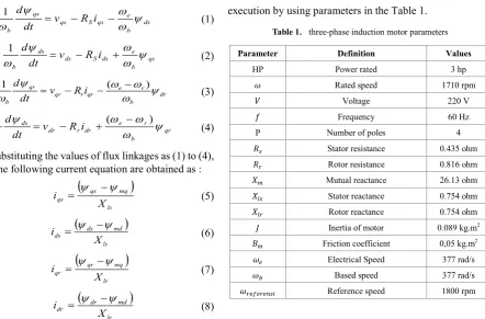
Table 1. three-phase induction motor parameters
Parameter Definition Values
HP Power rated 3 hp 𝜔𝜔 Rated speed 1710 rpm
𝑉𝑉 Voltage 220 V
𝑓𝑓 Frequency 60 Hz
P Number of poles 4 𝑅𝑅𝑠𝑠 Stator resistance 0.435 ohm
𝑅𝑅𝑟𝑟 Rotor resistance 0.816 ohm
𝑋𝑋𝑚𝑚 Mutual reactance 26.13 ohm
𝑋𝑋𝑙𝑙𝑠𝑠 Stator reactance 0.754 ohm
𝑋𝑋𝑙𝑙𝑟𝑟 Rotor reactance 0.754 ohm
𝐽𝐽 Inertia of motor 0.089 kg.m2
𝐵𝐵𝑚𝑚 Friction coefficient 0,05 kg.m2
𝜔𝜔𝑒𝑒 Electrical Speed 377 rad/s
𝜔𝜔𝑏𝑏 Based speed 377 rad/s
𝜔𝜔𝑟𝑟𝑒𝑒𝑟𝑟𝑒𝑒𝑟𝑟𝑒𝑒𝑟𝑟𝑠𝑠𝑟𝑟 Reference speed 1800 rpm
3. Svpwm
Technique
SVPWM technique is special switching scheme of six power IGBTs of a 3-phase inverter. It is one best way the Pulse Width Modulation (PWM) due to reduce minimum Total Harmonics Distortion (THD)[8][12]. Operation principle is rotation of this space vector can be executed by variable frequency device to generate three phase sine waves to go TIM. The three-phase voltage source can be changed to a space vector using following equation [12]:
3 / 4 3 / 2
0
v
e
πv
e
πe
v
V
=
a j+
b j+
c (15) Control signal of SVPWM techniuqe based on using following equation[12]:( )
d a a a tri a control V v v v VV
+ − = − 2 min ) max(
( )
d b b b tri b control V v v v VV
+ − = − 2 min ) max( (16)
( )
d c c c tri c control V v v v VV
+ − = − 2 min ) max(
Trigger signal is applied a triangle wave using switching frequency fs. SVPWM is taken from comparison control
Figure 1. Space vector limited amplitude
4. Genetic Algorithm
Genetic algorithm [20] is stochastic techniques to optimize based on the natural selection mechanism and genetic, which work with a population of solution. A fitness value derived from the problem’s objective function is assigned to each member of the population. Individuals that represent better solutions are awarded higher fitness value , thus enabling them to survive more generation. Commencing with an initial random population, successive generations of population are created by the operators reproduction, crossover and mutation to yield better solutions, which approach the optimal solution to the problem
The Genetic Algorithm (GA) offers an effective way for automatically searching or tuning of PID parameter [21] according to the dynamic behavior and signals of the measured system. It performs especially well when solving complex problems because it does not impose many limitations of traditional tehcniques. The better performance is obtained because of global and robust nature of GA, its ability of locating high performance areas in complex domains without experiencing the difficulties associated with high dimensionality or false optimation, and its computational efficiency. The technique has the capability to solve nonlinear and complex optimization problems. PID controller has good performance and have been applied in practice.
5. Design Tuning Pid-Ga
PID control system consists of three ways such as P (proportional), D (Derivative), and I (Integral), which each parameter has advantages and disadvantages. In the implementation of each way can work alone or combined. In the design of PID control system needs to be done is to set the parameters P, I, and D in order to the response of the output signal of system against certain entries as desired. PID control will correct error between the output with the input or settting point by caculating and give correction output [14]. In general, the PID controller has form of equation (17)[13].
( )
( )
( )
( )
dt t de K dt t e K t e K t u d t ip + +
=
∫
0 (17)
If equation (17) is converted to be PID controller transfer function, so that it will become equation (18)
( )
s Kp Ksi sKdG = + + (18)
Where Kp is the proportional gain, Ki is the integral gain,
and Kd is the derivative gain.
Performance criteria is intergated of square error (ISE) that can be evaluated analytical in the frequency domain. ISE performance criterion formula is as follow:
𝐼𝐼𝐼𝐼𝐼𝐼 = ∫ 𝑒𝑒∞ 2(𝑡𝑡)𝑑𝑑𝑡𝑡
0 (18)
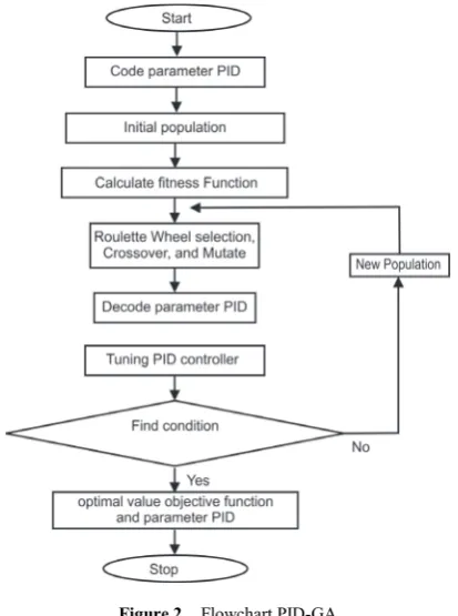
where 𝑒𝑒(𝑡𝑡) = 𝜔𝜔𝑟𝑟𝑒𝑒𝑟𝑟𝑒𝑒𝑟𝑟𝑒𝑒𝑟𝑟𝑟𝑟𝑒𝑒− 𝜔𝜔𝑟𝑟𝑟𝑟𝑟𝑟𝑟𝑟𝑟𝑟. Figure.2 show that
flowchart of PID-GA speed controller.
Figure 2. Flowchart PID-GA
Performance is measured by combination overshoot and ISE. It is entried to equation of time domain response. The objective function, 𝑓𝑓 is applied to evaluate the performance given by,
ISE OS
f =α× +β× (19)
where α and β as weight constant each element of objective function, OS shown overshoot of speed response and ISE refers to integrated square.
[image:3.595.329.536.274.552.2]Figure 3. Block mechanism of PID-GA
( )
( )
( )
m e m B Js s T s s G + ==
ω
1 (20)Parameters of genetic algorithm is shown on the Table.2, whereas contraint parameter PID is noticed by Table 3.
Table 2. Parameter Genetic Algorithm
Parameters Values
Population size 30 Maximum generation 50
Selection method Roulette wheel Crossover percentage 0,8 Extra range factor for crossover 0,4 Mutation percentage 0,3 Mutation rate 0,1
Table 3. Contraint of Parameter Pid
Parameter PID Kp Ki Kd
Minimum 0 0 0 Maximum 5 5 5
6. Block MATLAB/SIMULINK
This section, mechanism of PID-GA is separated by closed-loop speed control of three-phase induction motor using PID. Genetic algorithm is used to tuning parameter Kp,
Ki, dan Kd. Optimation error signal is shown by equation (18).
Whereas objective function refer to equation (19). Plant of induction motor only apply an simple equation which noticed by equation (20). Block mechanism PID-GA in MATLAB/SIMULINK is shown by Figure.4
Figure 4. Block mechanism design tuning PID-GA in
MATLAB/SIMULINK
Block closed-loop speed control of three-phase induction motor using PID is shown by Figure.5. It consists of block reference speed, block PID, block sinusoidal wave voltages controller, block SVPWM, block inverter, block filter, and block of dynamic induction motor. Block of dynamic induction motor uses DQ model. It is taken from equation (1)-(13). Block SVPWM is made from comparison signal voltages abc controller with signal trigger wave uses switching frequency fs.
7. Simulation Result
In the first case, simulation PID-GA is worked. Tuning of PID controller parameters is gained in simulation and shown on Table 4.
Table 4. Parameters Pid-Ga
Methods Kp Ki Kd
GA 3,4224 0,03291 4,4379
Whereas performance index consists of overshoot and ISE. It is looked at in Table.5
Table 5. Performance index of objective function pid-ga
Method OS ISE
GA 0,5% 2.919e+06
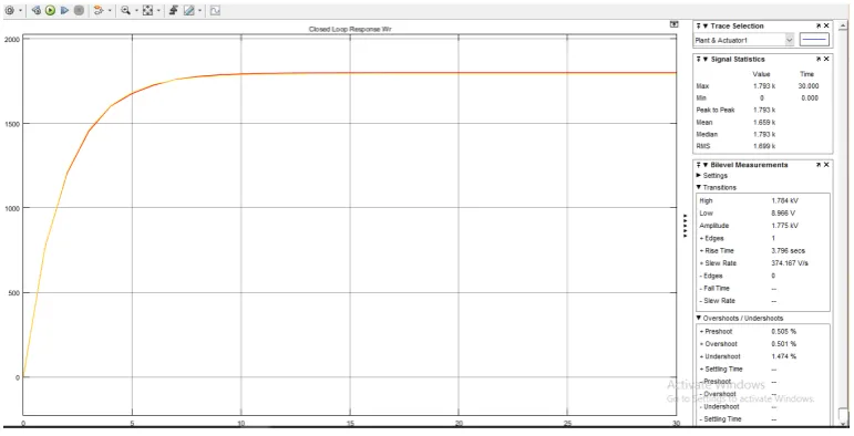
Graph optimal value of objective function genetic algorithm is noticed in Figure.6 and Graph response speed of induction motor using PID-GA is shown by Figure.7.
In other hand, simulation of the closed-loop speed control of three-phase induction motor using PID has resulted in form voltages abc controller, SVM, SVPWM, voltages of inverter, voltages inverter has been filtered, voltages dq, stator flux, rotor flux, mutual flux, stator current, rotor current, torque, and speed response of three-phase induction motor.
System response is applied variation load torque 20 Nm at 1 sec, 40 Nm at 1.25 sec, and 60 Nm at 1.5 sec. In the starting the operating full speed (1800 rpm) but no load until 1 sec. change the load torque will effect to decrease flux (Figure 14-16), and to derive speed response (Figure 19).
Table 6 summarizes the effect load torque to flux induction motor and Table 7 shows result in influence load torque to speed response.
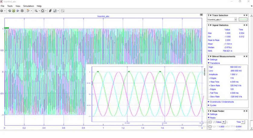
Figure 8 explains signals of voltages control phase a, phase b, and phase c. Magnitude of Voltages controller is used 1 volt.
Figure 9 demonstrates output of voltages SVM. It is seem that has magnitude 0.98 because SVM uses value of modulation 0.98.
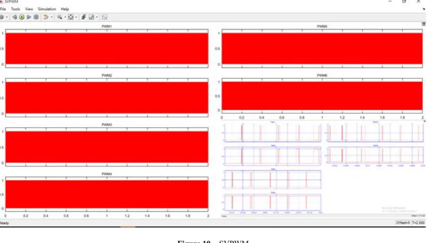
Figure 10 shows that It is output of SVPWM. It is used as power switching to impulse gate from inverter.
Figure 11 describes that It uses 240 volt for Inverter. Figure 12 draws that It is output of signal exited filter. This voltages have 236 volt at simultion.
Figure 5. Closed-loop speed control of three-phase induction motor using PID.
Figure 6. Optimal value of objective function PID-GA
[image:5.595.112.498.541.738.2]Figure 8. Voltages abc controller
Figure 10. SVPWM
[image:7.595.95.516.80.319.2]Figure 12. Voltages inverter hase been filtered
[image:8.595.93.517.250.539.2]Figure 14. Stator flux
[image:9.595.92.520.76.551.2] [image:9.595.93.518.79.304.2]Figure 16. Mutual Flux
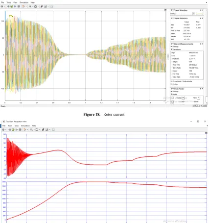
[image:10.595.94.521.77.529.2]Figure 18. Rotor current
Figure 19. Torque and speed induction mtoor
Table 6. Effect load torque to flux induction motor
Time (second) Load Torque TL(Nm) Rotor Flux Fr (Wb) Stator Flux Fs (Wb) Mutual Flux Fm (Wb)
0-0.7 0 167 173 168
0.7-0.9 0 170 175 170
1-1.25 20 166 172 166
1.25-1.5 40 157 169 160
1.5-1.75 60 143 166 148
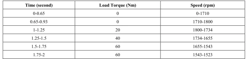
[image:11.595.95.520.618.721.2]Table 7. Effect load torque to rotor speed induction motor
Time (second) Load Torque (Nm) Speed (rpm)
0-0.65 0 0-1710
0.65-0.93 0 1710-1800
1-1.25 20 1800-1734
1.25-1.5 40 1734-1655
1.5-1.75 60 1655-1543
1.75-2 60 1543-1523
8. Conclusions
This paper presents speed control of three-phase induction motor using PID and a simple model for mechanism PID-GA. Both of them are designed is separated. At the simulation of mechanism PID-GA has been done, it had a good response system. It has found very low overshoot 0.5% and ISE 2.919X10⁶, so the simulating shown effective performance. It
also can find the tuning of the PID controller parameters for speed control of three-phase induction motor.
At the simulation experiment of closed-loop speed control of three-phase induction motor had been runned. The Rated speed 1710 rpm can be found at the time 0.65s. The average starting stator current is gained 111.58 A. The maximum starting torque is acquired 121,77 Nm. Breakdown torque or peak torque can be reach 68 Nm at the time 0.59s. When this simulation is added various load torque, it will gain and affect a decreasing stator flux and rotor flux, lifting stator current and rotor current, and speed of TIM will be decreased.
REFERENCES
[1] A. A. Ansari and D.M. Deshpande, “Mathematical Model of Asynchronous Machine in MATLAB Simulink,”
International Journal of Engineering Science and Technology, Vol. 2(5), 2010, pp1260-1267.
[2] Afianto, Rahmawan, “Simulasi pemodelan motor induksi tiga fase dengan sumbu D-Q dengan pemrograman MATLAB”,
Skripsi Teknik Elektro, Universitas Gadjah Mada, 2008. [3] Agustika, Richardus Dhimas Krisnawan, “Perancangan
kendali kecepatan mesin arus searah dengan menggunakan PID-Algoritma Genetika”, Tesis Teknik Elektro, Universitas Gadjah Mada, 2015.
[4] Chee-Mun Ong, Dynamic Simulation of Electric Machinery using Matlab/Simulink, New Jersey: Prentice Hall, 1997. [5] Dal Y. Ohm, Dynamic Model of induction motor for vector
control, Drivetech, Inc., Blacksburg, Virginia.
[6] Fitzgerald, A.E., Uman,S. D., Kindsley, C. Jr., Electric Machinery sixth edition , New york: McGraw Hill. 2002.
[7] Goldberg, D.E. Genetic Algorithms in Search, Optimization and Machine Learning. Addison- Wesley. 1989.
[8] Ismail , Noer Aziz, “Kendali V/F motor induksi dengan metode space vector modulation untuk penyaklaran dan estimasi kecepatan berbasis back electromotive force menggunakan mikrokontroller DSPIC” Skripsi Teknik Elektro, Universitas Gadjah Mada, 2013.
[9] K. K. Chouhan and G. B. Buch, "Improved direct torque control of induction motor," 2015 International Conference on Electrical, Electronics, Signals, Communication and Optimization (EESCO), Visakhapatnam, 2015, pp. 1-5. [10] K. L. Shi, T. F. Chan, Y. K. Wong and S. L. HO, “Modelling
and simulation of the three phase induction motor Using SIMULINK,” Int.J. Elect. Enging. Educ., Vol. 36, 1999, pp. 163–172.
[11] Maswood, A.I., and Wei, S., “Genetic algorithm based solution in PWM converter switching”, IEE Proc. Elect. Power Appl., Vol. 152, No.3, pp. 473-478, May. 2005. [12] Ned Mohan, Advanced Electric Drives: Analysis, Control
Modeling using Simulink, USA: Wiley. 2001.
[13] Ogata, Katsuhiko, Modern Control Engineering Fifth Edition.
Prentice Hall International, Inc. 2010.
[14] P. C. Crause, O. Wasynczuk, S. D. Sudhoff, Analysis of Electric Machinery and Drive Systems second edition. IEEE Wiley Press. 2001.
[15] P. S. Brainord, K. S. Sri and L. Dinesh, "Speed control of three-phase induction motor drives using automatically sensing controller based on fuzzy logic," 2015 International Conference on Electrical, Electronics, Signals, Communication and Optimization (EESCO), Visakhapatnam, 2015, pp. 1-6.
[16] Purwanto,Era dkk. “Pengembangan Metode Self Tuning Parameter PID Controller Dengan Menggunakan Genetic Algorithm Pada Pengaturan Motor Induksi Sebagai Penggerak Mobil Listrik”, Electronic Engineering Polythecnic Institute of Surabaya (EEPIS),2010.
[17] S. J. Chapman, Electric machinery fundamentals, Singapore: McGraw-Hill. 1991.
[18] Shopova, E. G. & Vaklieva-Bancheva, N. G. “Basic-A Genetic Algorithm for Engineering Problem Solution”,
Science Direct Computer and Chemical Engineering, Vol.30,pp. 1293-1309, June. 2006.
induction motor drives First edition, IEEE Willey Press. 2011.
[20] M.K Hassan, N.A.M Azubir, Nizam.H.M.I, S.F Toha, and B.S.K.K Ibrahim, “Optimal Design of Electric Power Assisted Steering System (EPAS) Using GA-PID Method”, International Symposium on Robotic and Intelligent Sensors
2012, Vol. 41,pp.614-621, 2012.