Constructing DNA-based Parallel Adder with Basic Logic
Operations in the Adleman-Liption Model
Sientang Tsai
Departmentof Information Management, Southern Taiwan University of Science and Technology, Yuan Kung District, Tainan City, Taiwan, R.O.C.
*Corresponding author: [email protected]
Copyright © 2013 Horizon Research Publishing All rights reserved.
Abstract
It is shown first by Adleman that deoxyribonucleic acid (DNA) strands could be employed towards calculating solution to an instance of The NP-complete Hamiltonian Path Problem (HPP). Lipton also demonstrated that Adleman’s techniques could be used to solve the satisfiability (SAT) problem. In this paper, it is demonstrated how the DNA operations presented by Adleman and Lipton can be used to construct bio-molecular parallel adder with basic logic operations in the Adleman-Lipton model.Keywords
Parallelism, Adleman-Lipton Model, DNA-based Computing, NP-complete Problem1. Introduction
Through advances in molecular biology [1], it is now possible to produce roughly 1018 DNA strands that fit in a test tube. Those 1018 DNA strands can also be applied to represent 1018 bits of information. Basic biological operation can be used to simultaneously operate 1018 bits of information. Or we can say that 1018 data processors can be executed in parallel.
The rest of the paper is organized as follows. Section 2, introduces DNA model of computation proposed by Adleman and his co-authors in detail. Section 3 we briefly introduce DNA algorithms based on the Adleman-Lipton model for constructing bio-molecular parallel adder with basic logic operations. The complexity of the proposed algorithm is also described. Conclusions are drawn in Section 4.
2. DNA Model of Computation
2.1. Abstract Descriptions of Biological Operations in DNA Model
In the last decade there have been revolutionary advances
in the field of biomedical engineering particularly in recombinant DNA and RNA manipulating. Due to the industrialization of the biotechnology field, laboratory techniques for recombinant DNA and RNA manipulation are becoming highly standardized. Basic principles about recombinant DNA can be found in [2]-[6]. In this subsection we describe eight biological operations that are useful for constructing bio-molecular parallel adder with basic logic operations. The method of generating DNA strains for the input operands of parallel N-bit adder is based on the proposed method in [7]-[8]. Basically it is a filtering model developed by L. Adleman (1996), which is memory-less in the sense that the strings themselves do not change during computation. Adleman extended the memory-less model to a memory-based filtering model by adding the so-called flip operation, which allows the implementation of n-bit registers used in this research.
A (test) tube is a set of molecules of DNA (a multi-set of finite strings over the alphabet {A, C, G, T}). Given a tube, one can perform the following operations:
1. Extract: Given a tube T and a short single strand of DNA, “s”, produce two tubes + (T, s) and – (T, s), where + (T, s) is all of the molecules of DNA in T which contain the strand “s” as a sub-strand and – (T, s) is all of the molecules of DNA in T which do not contain the short strand “s”.
2. Merge: Given tubes T1 and T2, yield ∪ (T1, T2), where
∪ (T1, T2) = T1∪T2. This operation is to pour two tubes into
one, with no changeof the individual strands.
3. Amplify: Given a tube T, the operation, Amplify (T, T1,
T2), will produce two new tubes T1 and T2so that T1 and T2
totally a copy of T (T1and T2 are identical) and T becomes
an empty tube.
4. Append: Given a tube T and a short strand of DNA,
“s”, and the operation will append the short strand, “s”, onto the end of every strand in the tube T. It is denoted by append (T, s).
5. Append-head: Given a tube T and a short strand of DNA, “s”, and the operation will append the short strand,
6. Detect: Given a tube T, say ‘yes’ if T includes at least one DNA molecule, and say ‘no’ if it contains none. It is denoted by detect (T).
7. Discard: Given a tube T, the operation will discard the tube T. It is denoted by discard (T).
8. Read: Given a tube T, the operation is used to describe a single molecule, which is contained in the tube T. Even if
T contains many different molecules each encoding a different set of bases, the operation can give an explicit description of exactly one of them. It is denoted by read (T).
2.2. Implementation of Biological operations in DNA Model
Experimental implementation of biological operations is very important for deciding whether any DNA-based algorithm to dealing with any problem can obtain the required answer(s) or not. The content of the following subsections cited from [6] is used to describe how biological operations used in the proposed algorithm are implemented.
1. Separate (T, s, T1, T2)
Affinity purification is used to extract any strands from T
containing s. The implementation of the biological operation uses a probe sequence that is complementary to the target sequence being found for. Probes are fixed to a surface, and capture through annealing any strands consisting of the target sequence. Then, captured strands perhaps are separated from the rest of the population by placing them in a separate solution, which is heated to break the bonds between the probes and the target sequence. Hence, the probe applied is the complementary sequence of
s. Retained strands are placed in one new tube T1 and the
remainder are placed in another new tube T2.
2. Merge ({Ti})
The contents of tubes {Ti}are simply merged by means of pouring. The number of tubes will generally be low, so this is considered to be a constant-time operation.
3. Discard (T)
The contents of T are discarded, and T is replaced by a new, empty tube.
4. Amplify (T, {Ti})
The polymerase chain reaction (PCR) is employed, with its initial input that is tube T. This reaction is applied to massively amplify (possibly small) amounts of DNA strands that begin and end with specific primer sequences. Since every strand in tube T is delimited by these sequences, they are all copied by the reaction. Then, the result of the PCR is divided equally between the specified numbers of tubes (the number of PCR cycles may therefore be adjusted to ensure a constant DNA volume per tube, regardless of the number of tubes).
5. Concatenate (s1, s2)
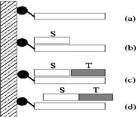
Two strands (labeled S and T in Figure 1) may be concatenated by the following process: create a linker
strand, which has a sequence that is the complement of S
followed by the complement of T. The linker strand is
[image:2.595.316.547.192.388.2]affixed to a surface with a magnetic bead (Figure 1(a)). Then, strand S is added to the solution, and anneals with the linker strand at the appropriate position (Figure 1(b)). Then, strand T is added to the solution, and this also anneals with the linker strand, at a position immediately adjacent to strand S (Figure 1(c)). Next, the ligase enzyme is added to the solution to seal the “nick” between S and T, forming a single strand which may be freed by heating the solution to break its bonds with the linker strand (Figure 1(d)).
Figure 1. Concatenation process: (a) Linker strand affixed to surface. (b) S anneals to linker strand. (c) T anneals to linker strand, adjacent to S. (d) S and T ligated to form a single strand, which is then freed by heating the solution.
6. Append-head (U, s)
The implementation of the concatenate ( ) operation denoted above may easily be applied to append a specific sequence, s, to the head of each strand in a tube U. The sequence s corresponds, in this case, to the strand S defined in Figure 1, and strand T in Figure 1 corresponds to the beginning sequence of every strand in the tube. In this case, only the beginningsequence of every strand anneals to the linker strand. Clearly, then, after a series of append-head() operations has been completed on a strand, its sequence will be made up of a number of sequences representing bit-strings.
7. Detect (T)
3. DNA Algorithms for Constructing
Basic Logic Operations
3.1. The Construction of Parallel One-bit XOR Operation
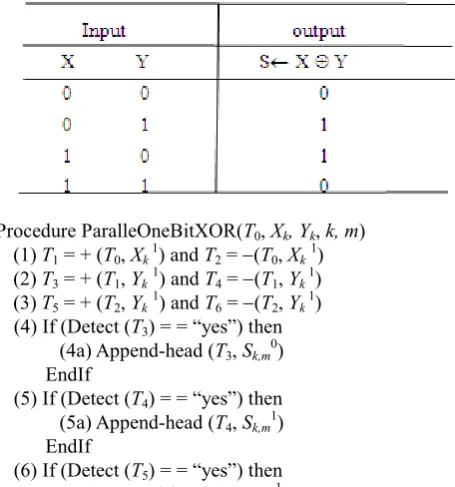
The Exclusive-OR (XOR) operation of a bit for two Boolean variables X and Y generates an output of 1 if both X
and Y have different values and 0 if they are the same. The ⊕ symbol represents the XOR operation. The four possible combinations for the XOR operation of a bit with two Boolean variables X and Y are as follows: 0 ⊕ 0 = 0, 0 ⊕ 1 = 1, 1 ⊕ 0 = 1, and 1 ⊕ 1 = 0.
A truth table is usually used with logic operation to represent all possible combinations of inputs and the corresponding outputs. The truth table for the XOR operation is shown in Table 1.
Assume that two one-bit binary numbers Xkand Yk, for 1 ≤k≤n, are used to represent the first input and the second input for the XOR operation of a bit respectively. Also suppose that Sk,m, for 1 ≤k≤n and 1 ≤m≤ 2, is applied to
represent the output for the one-bit XOR operation. From [7]-[8], for every bit Xkrepresenting the kth element for 1≤ k ≤ n, two distinct 15-base value sequences are designed. One represents the value “0” for Xk and the other represents the value “1” for Xk. For the sake of convenience, assume that
Xk1 denotes that the value of Xkis 1 and Xk 0denotes that the value of Xkis 0.Similarly, suppose that Yk1 denotes that the value of Yk is 1 and Yk 0denotes that the value of Yk is 0. Assume that Sk,m1 denotes that the value of Sk,m is 1 and Sk,m0 denotes that the value of Sk,mis 0.The following procedure is proposed to perform the parallel one-bit XOR operation.
Table 1. The truth table for the XOR operation of a bit with two Boolean variables X and Y
Procedure ParalleOneBitXOR(T0, Xk, Yk, k, m) (1)T1 = + (T0, Xk 1) and T2 = −(T0, Xk1) (2)T3 = + (T1, Yk1) and T4 = −(T1, Yk 1) (3)T5 = + (T2, Yk1) and T6 = −(T2, Yk 1) (4) If (Detect (T3) = = “yes”) then
(4a) Append-head (T3, Sk,m0) EndIf
(5) If (Detect (T4) = = “yes”) then
(5a) Append-head (T4, Sk,m1) EndIf
(6) If (Detect (T5) = = “yes”) then
(6a) Append-head (T5, Sk,m1)
EndIf
(7) If (Detect (T6) = = “yes”) then
(7a) Append-head (T6, Sk,m0) EndIf
(8) T0 = ∪(T3, T4, T5, T6)
EndProcedure
Lemma 1: The algorithm, ParallelOneBitXOR(T0, Xk, Yk,
k, m), can be employed to perform the biological parallel one-bit XOR operation.
Proof: The algorithm, ParallelOneBitXOR(T0, Xk, Yk, k,
m), is implemented by means of the extract, detect,
append-head and merge operations. Steps from (1) to (3) employ the extract operations to yield different tubes consisting of different inputs (T1 to T6). This implies, T1
includes all of the inputs that have Xk = 1, T2 contains all of
the inputs that have Xk = 0, T3 includes those inputs that
have Xk = 1 and Yk = 1, T4 contains those inputs that have Xk = 1 and Yk = 0, T5 consists of those inputs that have Xk = 0 and Yk = 1, and finally, T6 includes those that have Xk = 0 and Yk = 0. After having performed Step (1) through Step (3), four different inputs for the XOR operation of a bit as shown in Table 1 were poured into tubes T3 through T6,
respectively.
From Step (4) through (7), those steps are, respectively, applied to examine whether contains any input for tubes T3,
T4, T5, and T6 or not. If any a “yes” is returned from those
steps, then the corresponding append-head operations will be done. Because tubes T3, T4, T5 and T6, subsequently,
contains the input for the fourth row, the third row, the second row and the first row in Table 1, Sk,m0 from Step (4) and Step (7) is appended onto the head of every input in tubes T3 and T6 and Sk,m1 from Step (5) and Step (6) is, subsequently, appended onto the head of every input in tubes T4 and T5. After performing Step (4) through (7), four
[image:3.595.59.287.502.746.2]different outputs to the XOR operation of a bit as shown in Table 1 are appended into tubes T3 through T6. Finally, the
execution of Step (8) uses the merge operation to pour tubes
T3 through T6 into tube T0. Tube T0 contains the result
finishing the XOR operation of a bit as shown in Table 1. From ParallelOneBitXOR(T0, Xk, Yk,k, m), it takes three
extract operations, four detect operations, one merge
operation, one append-head operation and four test tubes to perform the function of one-bit XOR operation.
3.2. The Construction of Parallel One-bit AND Operation
The AND operation of a bit for two Boolean variables X and Y generates a result of 1 if both X and Y are 1. However, if either X or Y or both, are zero, then the result is 0. The dot ⋅ and ∧ symbol are both used to represent the AND operation. The four possible combinations for the AND operation of a bit with two Boolean variables X and Y are as follows: 0 ∧ 0 = 0, 0 ∧ 1 = 0, 1 ∧ 0 = 0, and 1 ∧ 1 = 1.
corresponding outputs. The truth table for the AND operation is shown in Table 2.
Table 2. The truth table for the AND operation of a bit with two Boolean variables X and Y.
Assume that two one-bit binary numbers Xk and Yk, for 1 ≤ k ≤ n, are employed to represent the first input and the second input for the AND operation of a bit respectively. Also assume that a one-bit binary number TMPk,m, for 1 ≤k ≤n and 1 ≤m≤ 3, is applied to represent the output for the AND operation of a bit. From [7]-[8], for every bit Xk representing the kth element for 1≤ k ≤ n, two distinct 15-base value sequences are designed. One represents the value “0” for Xk and the other represents the value “1” for Xk. For the sake of convenience, suppose that Xk 1 denotes that the value of Xkis 1 and Xk0denotes that the value of Xkis 0. Similarly, assume that Yk 1 denotes that the value of Ykis 1 and Yk 0 denotes that the value of Yk is 0. Suppose that
TMPk,m1 denotes that the value of TMPk,m is 1 and TMPk,m0 denotes that the value of TMPk,m is 0. The following procedure is offered to perform the parallel ANDoperation of a bit.
Procedure ParallelOneBitAND(T0, Xk, Yk, k, m)
(1) T1 = + (T0, Xk 1) and T2 = − (T0, Xk 1)
(2) T3 = + (T1, Yk 1) and T4 = − (T1, Yk 1)
(3) T5 = + (T2, Yk 1) and T6 = − (T2, Yk 1) (4) If (Detect (T3) = = “yes”) then
(4a)Append-head(T3,TMPk,m1) EndIf
(5) If (Detect T4) = = “yes”) then
(5a)Append-head(T4, TMPk,m0) EndIf
(6) If (Detect (T5) = = “yes”) then
(6a)Append-head(T5, TMPk,m0) EndIf
(7) If (Detect (T6) = = “yes”) then
(7a)Append-head(T6, TMPk,m0) EndIf
(8) T0 = ∪(T3, T4, T5, T6)
EndProcedure
Lemma 2: The algorithm, ParallelOneBitAND(T0, Xk, Yk, k,
m), can be used to perform the biological parallel AND operation of a bit.
Proof: The algorithm, ParallelOneBitAND(T0, Xk, Yk, k, m), is implemented via the extract, detect, append-head and
merge operations. Steps from (1) to (3) employ the extract
operations to form some different test tubes including different inputs (T1 to T6). That is, T1 includes all of the
inputs that have Xk = 1, T2 includes all of the inputs that
have Xk= 0, T3 includes those that have Xk= 1 and Yk= 1,
T4 includes those that have Xk = 1 and Yk = 0, T5 includes
those that have Xk = 0 and Yk = 1, and finally, T6 includes
those that have Xk = 0 and Yk= 0. Having finished execution of Step (1) through (3), it implies that four different inputs for the ANDoperation of a bit as shown in Table 2 were poured into tubes T3 through T6, respectively.
Steps from (4) to (7) are, respectively, used to test whether contains any input for tubes T3, T4, T5, and T6 or not.
If any a “yes” is returned for those steps, then the corresponding append-head operations will be done.
Next, Steps (4a),(5a),(6a) and (7a) use the append-head
operations to append TMPk,m1 and TMPk,m0 onto the head of every input in the corresponding tubes. After performing Step (4a) through (7a), four different outputs to the AND operation of a bit as shown in Table 2 are appended into tubes T3 through T6. Finally, the execution of Step (8)
applies the merge operation to pour tubes T3 through T6 into
tube T0. Tube T0 contains the result performing the AND
operation of a bit as shown in Table 2.
From ParallelOneBitAND (T0, Xk, Yk,k, m), it takes three
extract operations, four detect operations, one merge
operation, one append-head operation and four test tubes to perform the function of one-bit AND operation.
3.3. The Construction of Parallel One-bit OR Operation
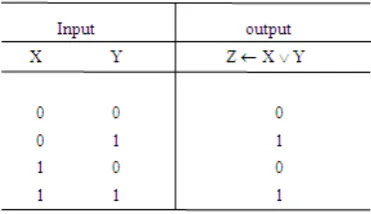
The OR operation of a bit for two Boolean variables X and Y produces a result of 1 if X or Y, or both, are 1. However, if both X and Y being equal to zero, then the result is 0. A plus sign + (logical sum) or ∨ symbol is normally applied to represent OR operation. The four possible combinations for the OR operation of a bit with two Boolean variables X and Y are as follows: 0 ∨ 0 = 0, 0 ∨ 1 = 1, 1 ∨ 0 = 1, and 1 ∨ 1 = 1.
A truth table is usually employed with logic operation to represent all possible combinations of inputs and the corresponding outputs. The truth table for the OR operation is shown in Table 3
Table 3. The truth table for the OR operation of a bit with two Boolean variables X and Y.
[image:4.595.339.525.593.700.2]is used to represent the output for the ORoperation of a bit. From[7]-[8], for every bit Xkrepresenting the kth element for 1≤ k ≤ n, two distinct 15-base value sequences are designed. One represents the value “0” for Xk and the other represents the value “1” for Xk. For the sake of convenience, suppose that Xk1 denotes that the value of Xk is 1 and Xk0 denotes that the value of Xkis 0. Similarly, assume that Yk 1 denotes that the value of Yk is 1 and Yk 0denotes that the value of Ykis 0. Suppose that Zk,m1 denotes that the value of
Zk,m is 1 and Zk,m0denotes that the value of Zk,m is 0. The following procedure is proposed to perform the parallel OR operation of a bit.
Procedure ParallelOneBitOR(T0, Xk, Yk,k, m) (1 )T1 = + (T0, Xk 1) and T2 = − (T0, Xk 1) (2) T3 = + (T1, Yk 1) and T4 = − (T1, Yk 1) (3) T5 = + (T2, Yk 1) and T6 = − (T2, Yk 1) (4) If (Detect (T3) = = “yes”) then
(4a) Append-head (T3, Zk,m1) EndIf
(5) If (Detect (T4) = = “yes”) then
(5a) Append-head (T4, Zk,m1) EndIf
(6) If (Detect (T5) = = “yes”) then
(6a) Append-head (T5, Zk,m1) EndIf
(7) If (Detect (T6) = = “yes”) then
(7a) Append-head (T6, Zk,m 0) EndIf
(8) T0 = ∪(T3, T4, T5, T6)
EndProcedure
Lemma 3: The algorithm, ParallelOneBitOR(T0, Xk, Yk, k,
m), can be used to perform the biological parallel OR operation of a bit.
Proof: The algorithm, ParallelOneBitOR(T0, Xk, Yk,k, m), is implemented via the extract, detect, append-head and
merge operations. Steps from (1) to (3) employ the extract
operations to form some different test tubes including different inputs (T1 to T6). That is, T1 includes all of the
inputs that have Xk= 1, T2 includes all of the inputs that
have Xk= 0, T3 includes those that have Xk = 1 and Yk = 1, T4
includes those that have Xk = 1 and Yk = 0, T5 includes those
that have Xk = 0 and Yk = 1, and finally, T6 includes those
that have Xk= 0 and Yk = 0. Having performed Step (1) through (3), this implies that four different inputs for the ORoperation of a bit as shown in Table 3 were poured into tubes T3 through T6, respectively.
Steps from (4) to (7) are, respectively, used to test whether contains any input for tubes T3, T4, T5, and T6 or not.
If any a “yes” is returned for those steps, then the corresponding append-head operations will be done. Next, Steps (4a),(5a),(6a) and (7a) use the append-head
operations to append Zk,m1 and Zk,m0 onto the head of every input in the corresponding tubes. After performing Step (4a) through (7a), we can find that four different outputs to the ORoperation of a bit as shown in Table 3 are appended into tubes T3 through T6. Finally, the execution of Step (8)
applies the merge operation to pour tubes T3 through T6 into
tube T0. Tube T0 contains the result performing the OR
operation of a bit as shown in Table3.
From ParallelOneBitOR(T0, Xk, Yk,k, m), it takes three
extract operations, four detect operations, one merge
operation, one append-head operation and four test tubes to perform the function of one-bit OR operation.
4. DNA Algorithms for Constructing
Parallel Adder
4.1. The Construction of a Parallel One-bit Adder
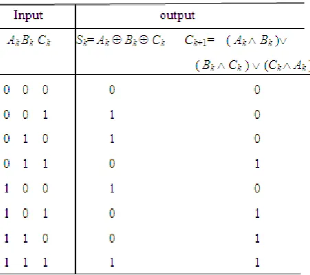
A one-bit adder is a Boolean function that forms the arithmetic sum of three inputs. It includes three inputs and two outputs. Two of the input bits represent augend and addend respectively, denoted by Ak and Bk. The third input represents the carry, denoted by Ck, from the lower significant position. The first output gives the value of the least significant bit of the sum, designated by Sk, for augend, addend and carry. The second output gives the output carry, designated by Ck+1, becoming the input carry of the next
one-bit adder. From the viewpoint of Boolean circuit implemented with logic gates to form an adder, we will find the Boolean functions specified in the Table 4 are given as follows:
Sk = Ak ⊕ Bk ⊕Ck
and
Ck+1 = ( Ak ∧ Bk ) ∨ ( Bk∧ Ck ) ∨ (Ck ∧ Ak ) ,
Where 1 ≤ k ≤ n.
The truth table of the one-bit adder is shown below:
Table 4. The truth table of the one-bit adder
For the reason of algorithmic design, suppose that three one-bit binary numbers, Ak, Bk andCk represent the input of a one-bit adder where 1 ≤k≤n. Two one-bit binary number,
[image:5.595.321.547.489.689.2]adder. From [7]-[8], two distinct DNA sequences are designed to represent the value “0” and “1” for every corresponding bit. For the sake of convenience in our representations, assume that Ak1 contains the value of Ak to be 1 and Ak0 contains the value of Ak to be 0. Also suppose that Bk1 contains the value of Bk to be 1 and Bk0 contains the value of Bk to be 0. Suppose that Ck1 contains the value of
Ck to be 1 and Ck0 denotes the value of Ck to be 0. Similarly, suppose that Sk,m1 defines the value of Sk,m to be 1 and
Sk,m0contains the value of Sk,m to be 0. Ck+1,m1 contains the value of Ck+1,m to be 1 and Ck+1,m0 denotes the value of Ck+1,m to be 0. The following procedure is proposed to perform the Boolean function of a parallel one-bit adder.
Procedure ParallelOneBitAdder(T0,Ak, Bk, Ck, k, m) ParalleOneBitXOR(T0, Ak, Bk, k, 1)
ParalleOneBitXOR(T0, Sk,1, Ck, k, 2) ParallelOneBitAND(T0, Ak, Bk, k, 1) ParallelOneBitAND(T0, Ck, Bk, k, 2) ParallelOneBitAND(T0, Ak, Ck, k, 3) ParallelOneBitOR(T0, TMPk,1, TMPk,2, k, 1)
ParallelOneBitOR(T0, Zk,1, TMPk,3,k, 2)
T1= +(T0, Zk,21 ) and T2= − (T0, Zk,21)
(9) If (Detect (T1) = = “yes”) then
(9a) Append-head (T1,Ck+11)
EndIf
(10) If (Detect (T2) = = “yes”) then
(10a) Append-head (T2, Ck+10)
EndIf
(11) T0= ∪ (T1, T2)
EndProcedure
Lemma 4: The algorithm, ParallelOneBitAdder (T0, Ak,
Bk, Ck, k, m), can be applied to perform the Boolean function of a parallel one-bit adder.
Proof: The algorithm, ParallelOneBitAdder(T0,Ak, Bk, C,
k,m) is implemented by performing procedure ParalleOneBitXOR(T0, Xk, Yk, k, m)and ParallelOneBitOR (T0, Xk, Yk, k, m) two times, where 1≤ m≤ 2, and ParallelOneBitAND (T0, Xk, Yk,k, m) three times, where 1≤
m ≤ 3. On the execution of Step (1), the algorithm, ParalleOneBitXOR (T0, Ak, Bk, k, 1), is employed to perform the function of one-bit XOR operation for input operand Ak and Bk. and tube T0 contains the result of Ak⊕ Bk, Next, the execution of Step (2) performs ParalleOneBitXOR(T0, Sk,1,
Ck, k, 2). Tube T0 includes the strands encoding the result of
Ak⊕ Bk⊕ Ck, which is the sum of three input bits Ak, Bkand previous carry Ck. Having performed Step (3) through Step (5), it performs ParallelOneBitAND(T0, Xk, Yk, k, m) sequentially and tube T0 consists of the result of one-bit
AND operation, Ak ∧ Bk , Bk ∧Ck , and Ck∧ Akin each step respectively. When Step (6) is executed, it performs ParallelOneBitOR(T0, TMPk,1, TMPk,2, k, 1). This algorithm
performs the function of one-bit OR operation for input operand TMPk,1 and TMPk,2 and tube T0 contains the result
of (Ak ∧ Bk) ∨ ( Bk ∧ Ck). When Step (7), ParallelOneBitOR(T0, Zk,1, TMPk,3,k, 2), is finished, tube T0
contains the result of (Ak ∧ Bk)∨( Bk ∧ Ck)∨ (Ck ∧ Ak). Sequentially we first separate the possible value of carry
Zk,2 into twotest tubes T1 and T2 by extract operation in Step
(8). In Step (9) and Step (10), if the detection result of tube T1 or tube T2 is yes, then we append the value “1” in tube T1
or “0” in tube T2 onto the head of corresponding strands at
position Ck+1. Thus the value of Zk,2 is transferredto Ck+1 by
pouring the DNA from tube T1 and T2 into T0 in Step (11).
From ParallelOneBitAdder(T0, Ak, Bk, Ck,k, m), it takes 22 extract operations, 30 detect operations, eight
append-head and merge operations and four test tubes to perform the logical operations XOR, AND, and OR for two corresponding input bits. Two output bits of a one-bit adder encode the sum and carry to the addition of three input bits. A value sequence for every output bit contains 15 base pairs. Therefore the length of a DNA strand, encoding two output bits has 30 base pairs, consisting of the concatenation of one value sequence for each output bit.
4.2. The Construction of a Parallel N-bit Adder
4.2.1. Generation of DNA Strands for the Input Operands of Parallel N-bit Adder
Now let’s add some binary numbers. Assume that there are three input operands of a parallel N-bit adder. Two of input operands, denoted by A and B, represent augend and addend respectively. The third input operand, C, represents the carry from the previous lower significant position. Suppose that AnAn-1…A2A1 is an n-bit binary number, which
represents an unsigned integer of augend A. Bit Anand A1
are the most significant bit and the least significant bit respectively. The range of the value to unsigned integer of n
bits is from 0 to 2n –1. For every bit A
k, 1≤ k ≤ n, from [7]-[8], two distinct 15-base value sequences are designed. One represents the value “0” for Ak and the other represents the value “1” for Ak. For sake of convenience in our representation, assume that Ak1 denotes the value of Akto be 1 and Ak0 denotes the value of Ak to be 0. For simplicity, we assume that BnBn-1…B2B1 is an n-bit binary number, which
represents an unsigned constant integer of addend B. The following procedure is used to generate 2n possible unsigned integer values A and constant value B.
Procedure Init (T0, n) (1) Append (T1, An1) (2) Append (T2, An0) (3) T0 = ∪(T1, T2)
(4) For k = n − 1 downto 1 (4a) Amplify (T0, T1, T2)
(4b) Append (T1, Ak1) (4c) Append (T2, Ak0) (4d) T0= ∪ (T1, T2)
End For
(5) For k = n downto 1 (5a) Append (T0, Bk) EndFor
EndProcedure
the second input integer, denoted by B, is 2 to be added. They are A= (A3 A2 A1) and B= (B3 B2 B1) =010 when
expressed in a 3-bit binary numbers. Also we suppose that the third input C1, represented the previous carry, is 0.
When the procedure Init (T0, n) is called from Step (1) of Algorithm 1 in Subsection 4.2.2, it is applied to initiate the possible combinations of binary number. Tube T0 is an
empty tube and regarded as an input tube for Init (T0, n),
and the number of bits encoding an unsigned integer, n, is regarded as the second parameter for Init (T0, n). Suppose
that the value of n is three. After the execution of Step (1) and Step (2) are performed, tube T1= {A31} and tube T2 =
{A30}. Then, after the execution of Step (3) is finished, the
merge operation makes tube T0 = {A31, A30}, tube T1 = ∅,
and tube T2 = ∅.
Because the value of q is three, Step (4a), (4b), (4c) and (4d) will be executed two times. After the first execution of Step (4a) is done, tube T0 =∅, tube T1= {A31, A30}, and tube
T2 = {A31, A30}. Next, after the execution of Step (4b) and
Step (4c) are performed, tube T1 = {A31 A21,
A
30 A21} andtube T2 = {A31 A20, A30 A20}. Then, after the first execution
of Step (4d) is finished, the merge operation makes tube T0
= {A31 A21, A30 A21, A31 A20, A30 A20}, tube T1=∅and tube
T2 =∅. Finally, after each execution of Step (4) and Step (5)
are done, the contents of tube T0 are shown in Table 5.
Lemma 5 is used to demonstrate the correctness of algorithm Init (T0, n).
Lemma 5: The algorithm, Init(T0, n), is used to generate the DNA strands for 2n possible unsigned integer values A and constant value B.
Proof: The algorithm, Init (T0, q), is implemented via
amplify, append and merge operations. Step (1) and Step (2) are subsequently applied to append DNA sequences, respectively, representing the value “1”and “0” for An,onto the end of every strand in tube T1 and tube T2. This means
that subsets containing the nth element to be 1 appear in tube T1 and subsets containing the nth element to be 0
appear in tube T2. Next, Step (3) is used to pour tube T1 and
T2into tube T0. This indicates that DNA strands in tube T0
include DNA sequences of An= 1 and An= 0.
Each time Step (4a) is performed, it uses amplify
operation to copy the contents of tube T0 into two new tubes,
T1 and T2, which are copies of T0. Tube T0 becomes empty.
Step (4b) and Step (4c) are used to subsequently append DNA sequences, respectively representing the value “1” and “0” for Ak, onto the end of every strand in tube T1 and
tube T2. This implies that strands containing the kth element to be 1 appear in tube T1 and strands containing the kth
element to be 0 appear in tube T2. Next, Step (4d) is used to
pour tube T1 and T2into tube T0. This indicates that DNA
strands in tube T0 include DNA sequences of Ak=1 and Ak=0. After repeating execution of Step (4a) through Step (4d), it finally produces tube T0 that consists of 2n DNA sequences
representing 2n different unsigned integer values A. After
append operation in Step (5a) is also performed n times, the results are binary string BnBn-1…B2B1 is appended at the end
of every DNA sequence in tube T0.
From Init (T0, n), it takes (n – 1) amplify operations, 3 ×n
append operations, n merge operations and three test tubes to generate the DNA strands for two input operands A and B. A value sequence for every bit contains 15 bases. Therefore, the length of a DNA strand, encoding two unsigned integer value of n bits, is 15 × (3 ×n) bases pair consisting of the concatenation of one value sequence for each bit.
Table 5. The result generated by Init (T0, n).
Tube The result generated by Init (T0, n)
T0
{A31A21A11B30B21B10, A31A21A10B30B21B10, A31A20A11B30B21B10, A31A20A10B30B21B10, A30A21A11B30B21B10, A30A21A10B30B21B10,
A30A20 A11 B30 B21 B10, A30 A20 A10 B30 B21 B10}
4.2.2. DNA Algorithms for Constructing Bio-molecular Parallel Adder with Basic Logic Operations
The parallel one-bit adder introduced in Section 4.1 figures out the arithmetic sum of two bits and a previous carry. Similarly, a binary parallel n-bit adder is also perform the arithmetic sum for the two input operands of n-bit and the input carry by means of performing this one-bit adder n
times. The following algorithm is proposed to perform the arithmetic sum for a parallel n-bit adder.
Algorithm 1. ParallelAdder(T0, A, B, C, n, m)
(1) Init (T0, n)
(2) Append (T0, C10)
(3) For k=1 to n
(3a) ParallelOneBitAdder (T0,Ak, Bk, Ck, k, m) EndFor
EndAgorithm
When the algorithm ParallelAdder (T0, A, B, C, n, m) is
performed, the execution of Step (1), Init (T0, n), in the Algorithm 1 is demonstrated in previous section. The argument A, B and C represent, respectively, the augend, addend, and carry in the parallel n-bit adder. The value of n
is three. Tube T0 with the result shown in Table 5 is
regarded as an input tube of this algorithm. Step (2) uses
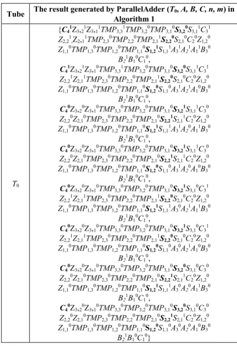
append operation to initialize the previous carry to be zero. When Step (3) is executed, it performs Step (3a), the algorithm ParallelOneBitAdder(T0, Ak, Bk, Ck, k, m) three times to compute the sum of Ak, Bk, and Ck for 1 ≤k ≤ 3. After the loop in Step (3) iterates execution for three times, the result of tube T0 is shown in Table 6. The boldfaces
inside the table represent the sum and carry of corresponding input operands A and B. Theorem 1 is applied to prove the correctness of algorithm ParallelAdder
(T0, A, B, C, n, m).
Theorem 1: The algorithm, ParallelAdder (T0, A, B, C, n,
m), can be applied to perform the Boolean function for a binary parallel adder of n bits.
Proof: The algorithm, ParallelAdder (T0, A, B, C, n, m),
is implemented via the extract, amplify, append, and merge
operations. On the execution of Step (1), the algorithm, Init (T0, n), is applied to generate the DNA strands for two input
operands A and B, represented by binary numbers
contains the DNA strands corresponding to these two encoded operands. Next the execution of Step (2) is mainly employed to set the initial value of previous carry C1to be
zero. When the first execution of Step (2), it uses the
append operation to append 15-base DNA sequences representing C10 onto the end of strand in T0. This is to say
that the first bit of the input carry C is set to zero. Thus tube
T0 contains the strands encoding two operands A and B with
[image:8.595.57.295.212.560.2]the zero previous carry C1
Table 6. The results generated by ParallelAdder (T0, A, B, C, n, m) in
Algorithm 1.
Tube The result generated by ParallelAdder (T0, A, B, C, n, m) in
Algorithm 1
T0
{C41Z
3,21Z3,11TMP3,31TMP3,20TMP3,10S3,20S3,11C31 Z2,21,Z2,11TMP2,30TMP2,20TMP2,11S2,20S2,10C20Z1,20 Z1,10TMP1,30TMP1,20TMP1,10S1,21S1,11A31A21A11B30
B21B 10C10,
C41Z
3,21Z3,10TMP3,31TMP3,20TMP3,10S3,20S3,11C31 Z2,21Z2,11TMP2,30TMP2,20TMP2,11S2,20S2,10C20Z1,20 Z1,10TMP1,30TMP1,20TMP1,10S1,20S1,10A31A21A10B30
B21B 10C10,
C40Z
3,20Z3,10TMP3,30TMP3,20TMP3,10S3,21S3,11C30 Z2,20Z2,10TMP2,30TMP2,20TMP2,10S2,21S2,11C20Z1,20 Z1,10TMP1,30TMP1,20TMP1,10S1,21S1,11A31A20A11B30
B21B 10C10,
C40Z
3,20Z3,10TMP3,30TMP3,20TMP3,10S3,21S3,11C30 Z2,20Z2,10TMP2,30TMP2,20TMP2,10S2,21S2,11C20Z1,20 Z1,10TMP1,30TMP1,20TMP1,10S1,20S1,10A31A20A10B30
B21B 10C10,
C40Z
3,20Z3,10TMP3,30TMP3,20TMP3,10S3,21S3,10C31 Z2,21Z2,11TMP2,30TMP2,20TMP2,11S2,20S2,10C20Z1,20 Z1,10TMP1,30TMP1,20TMP1,10S1,21S1,11A30A21A11B30
B21B 10C10,
C40Z
3,20Z3,10TMP3,30TMP3,20TMP3,10S3,21S3,10C31 Z2,21Z2,11TMP2,30TMP2,20TMP2,11S2,20S2,10C20Z1,20 Z1,10TMP1,30TMP1,20TMP1,10S1,20S1,10A30A21A10B30
B21B 10C10,
C40Z
3,20Z3,10TMP3,30TMP3,20TMP3,10S3,20S3,10C30 Z2,20Z2,10TMP2,30TMP2,20TMP2,10S2,21S2,11C20Z1,20 Z1,10TMP1,30TMP1,20TMP1,10S1,21S1,11A30A20A11B30
B21B 10C10,
C40Z
3,20Z3,10TMP3,30TMP3,20TMP3,10S3,20S3,10C30 Z2,20Z2,10TMP2,30TMP2,20TMP2,10S2,21S2,11C20Z1,20 Z1,10TMP1,30TMP1,20TMP1,10S1,20S1,10A30A20A10B30
B21B 10C10}
Step (3) is the main loop to perform the function of a parallel n-bit adder. On the first execution of Step (3a), it performs the algorithm, ParallelOneBitAdder(T0,Ak, Bk, Ck,
k, m), and uses three logic operations XOR, AND, and OR to perform the addition of three bits ( two significant bits and a previous carry). Repeat execution of Step (3a) until the most significant bits of the augend and addend are processed. The tube T0 contains the strands performing the
arithmetic sum of the two input operands and the zero previous carry. After finishing the execution of loop, tube
T0 includes the strands, encoded as Cn+1Sn,2
Sn-1,2Sn-2,2…S2,2S1,2, which represent the sum of two input
binary numbers AnAn-1…A2A1 , BnBn-1…B2B1 and carry
CnCn-1…C2C1.
From ParallelAdder (T0, A, B, C, n, m), it takes 22 × n
extract operations, 30 × n detect operations, 12 × n +1
append operations, 10×n merge operations, (n–1) amplify
operations and four test tubes to compute the sum of two operands and the previous carry. An n-bit binary number encodes the size of an operand. One bit encodes the carry of the sum. Therefore, (n + 1) bits correspond to the sum of three inputs. A value sequence for every bit contains 15 bases. Therefore, the total length of DNA strands, encoding the final result of the sum for two operands A, B and the previous carry C1, is 15 × (n + 1) base pairs consisting of
the concatenation of one value sequence for each bit.
5. Conclusions
There are two important features of DNA, at least in principle, to support the Adleman’s experiment for solving the Hamiltonian Path Problem (HPP): Watson-Crick complementarity and massive parallelism. Taking advantages of these features, many papers have presented for designing DNA procedures and algorithms to solve various NP-complete problems [9]-[15]. In this paper, based on biological operations in the Adleman-Lipton model, we propose an algorithm for constructing parallel adder with fundamental biological logic operations. The complexity of algorithm for the number of tubes, the number of DNA library strands, the longest length of DNA library strands, and the number of biological operations are O(1), O (2n), O (15 × n) and O (n), respectively.
The present algorithm has several advantages lying in its massive parallelism as described below. First, operations needed in the algorithm are performed in a fully automated manner in lab level. It is essential not only for the speedup of computation but also for error-free computation. Second, the proposed procedures are realizable practically, because every procedure can be implemented and every DNA manipulation in the procedure is feasible in their lab. Third, proposed algorithm also shows that arithmetic computation can directly be performed with biological operations. This indicates the Boolean circuits are not needed to perform mathematical operations on a molecular computer. Fourth, the proposed algorithm takes a number of steps being polynomial in the computational complexity.
Although the future of biological computation theory and its potential for physical realization is unclear, we have many evidences for showing the ability of DNA computing to solve many simple problems. The authors hope that this paper to demonstrate that molecular computing is a technology worth pursuing.
Acknowledgements
The author would like to give many thanks to Dr. Amos who is the author of the 6th reference and the 16th reference
for proposing valuable information about implementation of biological operations.
REFERENCES
[1] R. R. Sinden. DNA Structure and Function. Academic Press, 1994.
[2] J. Watson, M. Gilman, J. Witkowski, and M. Zoller, Recombinant DNA (2nd edition). Scientific American Books, W. H. Freeman and Co., 1992.
[3] J. Watson , N. Hoplins, J. Roberts, and et. al. Molecular Biology of the Gene. Benjamin/Cummings Menlo Park CA., 1987.
[4] G. M. Blackburn, and M. J Gait, Nucleic Acids in Chemistry and Biology. IRL Press, 1990.
[5] F. Eckstein, Oligonucleotides and Anologues. Oxford University Press. , 1991.
[6] M. Amos, Theoretical and Experimental DNA Computation. Springer, ISBN 3540657738, 2005.
[7] R. S. Braich, J. Clifford, W.K. Paul Rothemund, D. Hwang , N. Chelyapov, and L. M. Adleman, Solution of a satisfiability problem on a gel-based DNA computer. Proceedings of the 6th International Conference on DNA Computation in the Springer-Verlag Lecture Notes in Computer Science series, 1-27, 2001.
[8] L. M. Adleman, R. S Braich, J. Clifford, W.K. Paul Rothemund, D. Hwang, and N. Chelyapov, Solution of a 20-Variable 3-SAT Problem on a DNA Computer. Science,
Vol. 296, Issue 5567, 499-502, 19 April, 2002 .
[9] R. J. Lipton, DNA solution of hard computational problems, Science, 268, 542-545, 1995.
[10] Q. Quyang, P.D. Kaplan, S. Liu, and S. Libchaber A., DNA solution of the maximal clique problem. Science, 278:446-449, 1997.
[11] M. Amos, DNA Computation, Ph.D. Thesis, department of computer science, the University of Warwick, 1997. [12] W.L. Chang , M. Guo, and M. Ho , Towards solution of the
set-splitting problem on gel-based DNA computing, Future Generation Computer Systems, Vol. 20, Issue 5, June 15, 875-885, 2004.
[13] W. L. Chang, M. Ho, and M. Guo, Molecular solutions for the subset-sum problem on DNA-based supercomputing. BioSystems, Vol. 73, No. 2, 117-130, 2004.
[14] W.L. Chang, M. Ho, and M. Guo, Fast parallel molecular algorithms for DNA-based computation: factoring integers", IEEE Transactions on Nanobioscience, Vol. 4, No. 2, 149-163, 2005.
[15] W.L.Chang, Fast Parallel DNA-based Algorithms for Molecular Computation: the Set-Partition Problem. IEEE Transaction on NanoBioscience, Vol. 6, No. 1, March, 2007. [16] M. Amos. “DNA Computation”, Ph.D. Thesis, department of