International Journal of Emerging Technology and Advanced Engineering
Website: www.ijetae.com (ISSN 2250-2459,ISO 9001:2008 Certified Journal, Volume 5, Issue 3, March 2014)
560
Experimental Investigation for Laser Cutting on Cylindrical
Surface Using Co
2
Laser Using DOE Approach
R. J. Ajudiya
1, A. A. Shaikh
21
Assistant professor Shri Swami Atmanand Saraswati Institute of Technology,Surat-395006, Gujarat. India
2Associate Professor, Sardar Vallabhbhai National Institute of Technology,Surat-395007, Gujarat, India
Abstract— The laser cutting on cylindrical surface can be
employed by using laser as a source for evaporation of material. The control of power with steady position of laser head and the constant rotational speed of workpiece with axial motion at the autofocus distance from workpiece to laser head. The present work deals with imparting laser beam on rotating and axially moving cylindrical workpiece a single laser beam evaporates the material from the workpiece cylindrical surface. A microprocessor based work holding device is developed for provide the linear and rotary motion to workpiece. The simultaneous motion of workpiece against the steady laser beam generates the step cutting. By using the parameters like power, rotational speed, axial movement of workpiece and the generated depth value obtained by the experimentation is used for statistical analysis to obtain the predictive model. The predictive model developed for acrylic cylindrical shape of material found with fair closeness with experimental depth of cut obtained.
Keywords— Co2 laser, cylindrical surface, DOE, Full
factorial, micro machining,
I. INTRODUCTION
The basic process of laser machining is the use of a focused light beam to generate highly localized heating that melts the material. The molten material is subsequently blown away by a gas jet. Controlled, local laser heating can also be used to modify surface layers and textures of materials. One of the potential advantages with laser machining is that the cutting is a contamination-free, near-zero force operation, thereby eliminating the relatively high force loads and contamination potential common with traditional machining methods [1]. High intensity laser beam can be directed to a narrow region in order to instantly evaporate material with very narrow heat affected zone. This ability to cut instantly with extremely narrow laser beam distinguishes it from other cutting methods. The key to success in precision cut by laser depends on many factors such as laser characteristics, material properties of the specimen, and manufacturing parameters [2]. In precision manufacturing the quality of the cut is often measured based on the shape of the groove and amount of material removal.
Therefore, better understanding of the process and role of various parameters are essential for investigation [3-4].
International Journal of Emerging Technology and Advanced Engineering
Website: www.ijetae.com (ISSN 2250-2459,ISO 9001:2008 Certified Journal, Volume 5, Issue 3, March 2014)
561 Micro-turning using diamond tool is often used for processing cylindrical samples. However, the use of diamond tool has many limitations. First, as it is a contact-type machining process, the tool may undergo irregular wear resulting in increase of production cost as well as defects or cracks on the machined surface due to brittle nature of ceramic materials [10].
II. EXPERIMENTAL PROCEDURE
The experiments are performed on the MERCURY Laser Pro Co2 laser machine 25 watt capacity and pure
[image:2.612.380.491.207.311.2]acrylic cylindrical specimen with 15 mm diameter is selected as shown in fig.1. Here acrylic material is preferred due to the absorptivity of laser beam energy is unity [11].
Fig.1 Cylindrical specimen of acrylic material of 15mm diameter
Laser cutting on acrylic material is non toxic process and due to its transparency generated cavity can be easily measured in the optical measurement system with higher accuracy. Co2 laser machine works with interfacing
software. In the Co2 laser machine the input parameters are
power and speed of laser head. On the control console power and speed are in the percentage form (i.e. 100% power = 25 watt power), the maximum travelling speed of laser head is 42 IPS (inch per second, i.e. 100% speed = 42 inch per second). The experiments are performed at the focus distance of 50 mm.
The machine setup used in present work is Co2 laser
machine which removes the materials by two mode vector mode and raster mode. Vector mode gives the line cut or curvature cutting where the raster cutting cuts the cavity on the material using dot per inch concept. In both the cases laser head is in moving condition. For laser cutting on the cylindrical surface the steady position of head is achieved by overlapping the numbers of points on the one plane using interfacing software. As the numbers of overlapping points are increased then the steady position of laser head is achieved with the constant laser beam for the particular time period is also increased.
[image:2.612.85.255.318.428.2]Numbers of overlapping points and the time of steady position of head is linearly in proportion to amount of energy delivered. In the whole experiments the 5000 numbers of overlapping points are placed on the one plane of laser machine interfacing software as shown in fig.2 and it gives the continuous laser beam for 60 seconds.
Fig.2. overlapping points on one plane
A. Micro Processor Base Attachment
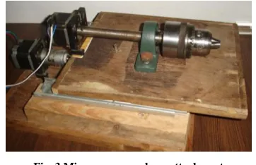
As shown in fig.3 microprocessor base attachment is made for providing speed and linear feed to the specimen. This attachment works on the concept of CNC. It is operated by M-code and G-code. Here attachment is use in the laser cutting so there is no cutting load in the process so it is decided to make the attachment from the plywood. This construction is capable enough to support the moving parts and transmit the perfect motion to the specimen.
Fig. 3 Micro processor base attachment
B. Hybrid Computer interface of micro processor base attachment
The attachment works on the CNC controller interface. Various CNC controllers are available. it is not possible to give different feed values for the individual motor by using single block. By giving the different magnitude of travel and keeping same feed value in the same block different motion of motor can be achieved but it is not suitable for measurement aspects. To overcome this problem, it is decided to use two simultaneous CNC controlling software for independent motion of each motor. To make such thing possible the separate motor connection pin connections are given to the individual CNC controlling software.
[image:2.612.353.534.429.546.2]International Journal of Emerging Technology and Advanced Engineering
Website: www.ijetae.com (ISSN 2250-2459,ISO 9001:2008 Certified Journal, Volume 5, Issue 3, March 2014)
562 By using this hybrid controlling technique individual motor can easily control and motion measurements are perfectly done.
The design of experiments (DOE) method is followed for deciding the numbers of experiment run. The numbers of parameters are three or less than three the full factorial method is suitable for the optimization [12-13]. For laser cutting on the cylindrical surface input parameters are power (p), rotational speed of cylindrical workpiece (s) and axial feed of workpiece (f).
Initial trials are taken to find feasible range of working. The parameters speed feed and power is selected in such a way that the minimum and maximum depth cut on the specimen can easily measured by using available measurement systems. The levels of power are 80%, 90%, and 100% is selected because below 80% power the turning which is appear on the specimen is not suitable for measurement. The speed levels are 50 rpm, 75 rpm and 100 rpm selected because below 50 rpm high amount of material is evaporated from specimen surface and it cause to parting off of specimen or bending, where as higher than 100 rpm speed gives the very less material removal from the specimen surface. The feed levels are 2.5mm/minute, 4.5mm/minute and 6.25 mm/minute are selected higher the feed value generates the striation effects are observed and the federate less then 2.5mm/minute the motion of stepper motor may not be observed smooth motion which may create the digging spot on specimen.
The sets of experiments are performed as suggested by the DOE full factorial method by taking the autofocus as shown in fig.4 and maintaining the alignment.
Fig.4. Auto focus of laser head with respect to cylindrical specimen
By setting the different power levels on Co2 laser machine and speed and feed on the attachment cylindrical specimen is machined and after micro machining specimen appears as shown in fig.5.
Fig.5. specimen after micro machining with varying power, speed and feed
The generated depths are scanned by needle scanner Roland model Picza 40 as shown in fig.6.
Fig.6. Scanning of specimen in Roland model Picza 40 needle scanner
International Journal of Emerging Technology and Advanced Engineering
Website: www.ijetae.com (ISSN 2250-2459,ISO 9001:2008 Certified Journal, Volume 5, Issue 3, March 2014)
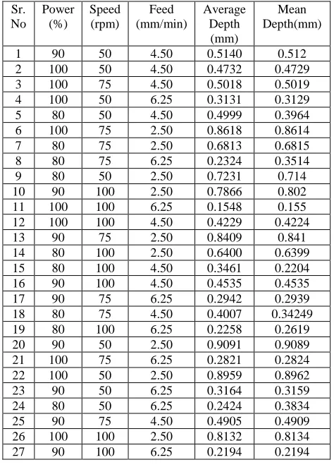
[image:4.612.50.287.168.499.2]563 Table I
summery of depth value obtained for particular power, speed and feed.
Sr. No
Power (%)
Speed (rpm)
Feed (mm/min)
Average Depth
(mm)
Mean Depth(mm)
1 90 50 4.50 0.5140 0.512 2 100 50 4.50 0.4732 0.4729 3 100 75 4.50 0.5018 0.5019 4 100 50 6.25 0.3131 0.3129 5 80 50 4.50 0.4999 0.3964 6 100 75 2.50 0.8618 0.8614 7 80 75 2.50 0.6813 0.6815 8 80 75 6.25 0.2324 0.3514 9 80 50 2.50 0.7231 0.714 10 90 100 2.50 0.7866 0.802 11 100 100 6.25 0.1548 0.155 12 100 100 4.50 0.4229 0.4224 13 90 75 2.50 0.8409 0.841 14 80 100 2.50 0.6400 0.6399 15 80 100 4.50 0.3461 0.2204 16 90 100 4.50 0.4535 0.4535 17 90 75 6.25 0.2942 0.2939 18 80 75 4.50 0.4007 0.34249 19 80 100 6.25 0.2258 0.2619 20 90 50 2.50 0.9091 0.9089 21 100 75 6.25 0.2821 0.2824 22 100 50 2.50 0.8959 0.8962 23 90 50 6.25 0.3164 0.3159 24 80 50 6.25 0.2424 0.3834 25 90 75 4.50 0.4905 0.4909 26 100 100 2.50 0.8132 0.8134 27 90 100 6.25 0.2194 0.2194
III. DEVELOPING PREDICTIVE MODEL FOR DEPTH VALUE
[image:4.612.39.296.640.687.2]The values of average depth are added in to the statistical software worksheet. Statistical analysis is done by the statistical software for finding out the predictive equations of the response values individually and calculating the analysis of variance (ANOVA). The results of statistical observations are mentioned in table II, III, and IV.
Table II
General Linear Model : Depth(d) verses Power(p), Speed (s) and Feed (f).
Factor Type Levels Values
p Fixed 3 80,90,100
s f
Fixed Fixed
3 3
50,75,100 2.50,4.50,6.25
Table III
Analysis of Variance for Depth (d) Using Adjusted SS for Tests
Source DF Seq SS Adj SS Adj MS F P p 2 0.045689 0.045689 0.022844 15.07 0.002 s 2 0.015261 0.015261 0.007630 5.03 0.038 f
p*s p*f s*f Error
2 4 4 4 8
1.346203 0.011552 0.022905 0.012094 0.012126
1.346203 0.11552 0.022905 0.012094 0.12126
0.673101 0.002888 0.005726 0.003024 0.001516
444.07 1.91 3.78 1.99
0.000 0.203 1.052 0.188
Total 26 1.165830
S = 0.0389327, R-Sq = 99.17%, R-Sq (adj) = 97.31%
Table IV
Regression Analysis: Depth(d) verses Power(p), Speed (s) and Feed (f).
Predictor Coef SE Coef T P
Constant 0.9153 0.1253 7.31 0.000 p 0.004039 0.001277 3.16 0.004 s
f
-0.00183 -0.14492
0.000510 0.006806
-3.59 -21.29
0.002 0.000
S = 0.0541838, R-Sq = 95.4%, R-Sq (adj) = 94.8%
A. Analysis for conversations of predictive values and actual result obtain
The analysis of variance gives the P value less than 0.05 for the individual parameters p, s and f but for the combination of two parameters like p*s, p*f, and s*f P value is higher than 0.005 so combination of parameters are neglected in the predictive equations. The regression analysis gives the mathematical equation of the output parameters like depth in the form of the input variables power speed and feed. The individual equation of depth is as mention below.
d = 0.915 + 0.00404p – 0.00183s – 0.145f
International Journal of Emerging Technology and Advanced Engineering
Website: www.ijetae.com (ISSN 2250-2459,ISO 9001:2008 Certified Journal, Volume 5, Issue 3, March 2014)
[image:5.612.42.297.166.445.2]564 Table V
summery of errors and absolute error of depth obtained from experiments and analytical equation.
Sr. No Powe r (%) Spee d (rpm) Feed (mm/min ) Depth by Experimen t (mm). Depth by Eq. (mm). Error (mm) Absolute Error (mm)
1 90 50 4.5 0.514 0.5346 -0.0206 0.0206
2 100 50 4.5 0.4732 0.575 -0.1018 0.1018
3 100 75 4.5 0.5018 0.5292
5
-0.02745 0.02745
4 100 50 6.25 0.3131 0.3212
5
-0.00815 0.00815
5 80 50 4.5 0.4999 0.4942 0.0057 0.0057
6 100 75 2.5 0.8618 0.8192
5
0.04255 0.04255
7 80 75 2.5 0.6813 0.7384
5
-0.05715 0.05715
8 80 75 6.25 0.2324 0.1947 0.0377 0.0377
9 80 50 2.5 0.7231 0.7842 -0.0611 0.0611
1 0
90 100 2.5 0.7866 0.7331 0.0535 0.0535
1 1
100 100 6.25 0.1548 0.2297
5
-0.07495 0.07495 1
2
100 100 4.5 0.4229 0.4835 -0.0606 0.0606
1 3
90 75 2.5 0.8409 0.7788
5
0.06205 0.06205
1 4
80 100 2.5 0.64 0.6927 -0.0527 0.0527
1 5
80 100 4.5 0.3461 0.4027 -0.0566 0.0566
1 6
90 100 4.5 0.4535 0.4431 0.0104 0.0104
1 7
90 75 6.25 0.2942 0.2351 0.0591 0.0591
1 8
80 75 4.5 0.4007 0.4484
5
-0.04775 0.04775 1
9
80 100 6.25 0.2258 0.1489
5
0.07685 0.07685
2 0
90 50 2.5 0.9091 0.8246 0.0845 0.0845
2 1
100 75 6.25 0.2821 0.2755 0.0066 0.0066
2 2
100 50 2.5 0.8959 0.865 0.0309 0.0309
2 3
90 50 6.25 0.3164 0.2808
5
0.03555 0.03555
2 4
80 50 6.25 0.2424 0.2404
5
0.00195 0.00195
2 5
90 75 4.5 0.4905 0.4888
5
0.00165 0.00165
2 6
100 100 2.5 0.8132 0.7735 0.0397 0.0397
2 7
90 100 6.25 0.2194 0.1893
5
0.03005 0.03005
Average 0.00036
7
0.04250 4
IV. RESULT AND DISCUSSION
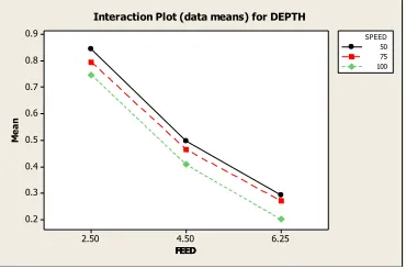
By varying the power, speed and feed the cylindrical specimen is micro machined in Co2 laser machine and obtained depth values are measured in needle scanner. By performing the experimentation it is observed that the depth value is inversely proportional to the feed value. As the feed increase the depth is decrease for particular speed level constant as mention in fig.7.
FEED FEED M e a n 6.25 4.50 2.50 0.9 0.8 0.7 0.6 0.5 0.4 0.3 0.2 SPEED 100 50 75
Interaction Plot (data means) for DEPTH
Fig.7 Depth versus feed for particular speed levels
Depth value is directly proportional to the power, as the power is increase then the micro machined specimen depth is also increase as prescribed in fig.8. The single line shows the mean value of depth.
POWER D EP TH 100 95 90 85 80 1.0 0.9 0.8 0.7 0.6 0.5 0.4 0.3 0.2 0.1
[image:5.612.337.548.187.335.2]Matrix Plot of DEPTH vs POWER
Fig.8 Depth versus power including mean value
Similarly depth is indirectly proportional to the speed value. As the speed is increases the depth of micro machined specimen is decreases for particular power level is constant as prescribed in Fig.9.
SPEED SPEED M e a n 100 75 50 0.60 0.55 0.50 0.45 0.40 POWER 100 80 90
Interaction Plot (data means) for DEPTH
Fig.9 Depth versus speed for particular power level constant.
V. CONCLUSION
The experiments conducted on acrylic cylindrical using Co2 laser machine
Increase in power tends to increase the cutting depth on cylindrical specimen.
Increase in speed of rotation tends to decrease the cutting depth on cylindrical specimen
Increase in the linear feed results the decrement in cutting depth on cylindrical specimen.
[image:5.612.340.545.397.533.2] [image:5.612.77.262.554.676.2]International Journal of Emerging Technology and Advanced Engineering
Website: www.ijetae.com (ISSN 2250-2459,ISO 9001:2008 Certified Journal, Volume 5, Issue 3, March 2014)
565 REFERENCES
[1] Jeff. Hecht, “The laser guide book”, McGraw-Hill Company,
Singapore, (1986) 1 to 75, 132-149.
[2] W.M. Steen, “Laser material processing” Springer-Verlag Limited,
London, (2005), 1-9, 61-152.
[3] Salman Nisar, M.A.Sheikh , “The effect of material thickness, laser
power and cutting speed on cut path deviation in high-power diode laser chip-free cutting of glass”, Optics & Laser Technology 42 (2010) 1022–1031
[4] X.C. Wang, H.Y.Zheng, “High quality femtosecond laser cutting of
alumina substrates”, Optics and Lasers in Engineering 48 (2010) 657–663
[5] P. Dumitrescu, P. Koshy, High-power diode laser assisted hard
turning of AISI D2 tool steel, International Journal of Machine Tools & Manufacture 46 (2006) 2009–2016
[6] H. Attia, S. Tavakoli, Laser-assisted high-speed finish turning of superalloy Inconel 718 under dry conditions, Manufacturing Technology 59 (2010) 83–88
[7] J. Booth, Recent application of pulsed lasers in advanced materials processing, Thin Solid Films (2004) 453–454.
[8] A.S. Kuar, B. Doloi, B. Bhattacharyya, Modeling and analysis of
pulsed Nd:YAG laser machining characteristics during micro-drilling of zirconia(ZrO2), International Journal of Machine Tools and Manufacture 46 (2006) 1301–1310.
[9] K. Farooq, A. Kar, Removal of laser-melted material with an assist gas, Journal of Applied Physics 83 (1998) 12.
[10] G. Kibria a,n, B.Doloi b, B.Bhattacharyya, Experimental
investigation and multi-objective optimization of Nd:YAG laser micro-turning process of alumina ceramic using orthogonal array and grey relational analysis, Optics & Laser Technology 48 (2013) 16–27
[11] A A Shaikh, A M Varsi, IJIRSET.2014.0309018
[12] Jiju Antony, Elsevier Science & Technology Books, (2003) ISBN: 0750647094.
[13] Douglas C. Montgomery, John Wiley & Sons, Inc, (2013) ISBN