FPGA Implementation of Efficient Face Detector
for Very Low Resolution Images
P.Reshmika1, M.V.Gnaneswara Rao2
M.Tech, Associate Proff, VLSI Design, Shri Vishnu Engineering College for Women
Abstract: Face detection is identifying or verifying the face from the input image. Face detection and tracking has been an active research area for a long time because it is the initial and important step in many different applications, such as video surveillance, face recognition, image enhancement, video coding. The proposed system provides good face detection of images that have low resolution. Applications like defence and security systems demand real time face Recognition systems, when other biometric techniques are not efficient. Eigen values are used in face recognition systems because they are sensitive for precision. Floating point operations are used in Eigen values but they are costly to implement on hardware. .Fixed point technique provides the flexibility in face recognition systems. This paper is implemented to provide solution for the [1] VLR (very low resolution problem) in face recognition which means the resolution of image is less than 16×16 those are captured from long distances. Existing face detection algorithms such as SR (super resolution) are not providing high performance image detection on very low resolution images. The proposed technique improves the resolution of the image by considering two phases1) the error measurement on high resolution image. 2) Training phase.
The proposed architecture of RLSR based Face detection has been designed using Verilog HDL, simulated using Modelsim simulator and implemented on virtex 5 FPGA kit. Experimental results of the proposed technique shows the increased performance in terms of image quality and recognition accuracy. It is power efficient method and employed for portable applications.
Keywords: Very low resolution (VLR), high resolution (HR). Super resolution (SR), relationship learning based super resolution (RL-SR), linearity clustering
I. INTRODUCTION
The face recognition system is an application which is used for identifying or Verifying a person from a digital image. The mobile phone is a very interesting application for advanced face recognition. Now a days increasing number of applications i,e personal authentication (e.g., access control, surveillance of people in public places, transactions security and human-computer interaction demands efficient face detection. Several techniques have been implemented to carry out this application. One method is by comparing the face features from input image to the database image. [4] Baker and Kanade implemented a method based on a Gaussian pyramid and Laplacian pyramid model and employed the Bayesian theory, steerable pyramid to extract multi orientation and multi scale information of low level features from both lr and hr face images to obtain the super-resolved face image. A Biometric is a measurable parameter of a human being that can be used to automatically recognise an individual or identify an individual’s identity. [7]Biometric measurements are classified into physiological (like finger print recognition, facial recognition, iris scan, hand scan) behavioural characteristics (data derived from an action like voice scan, signature scan, and key stroke scan). Face recognition is accurate and allows for high enrolment and verification rates. It can use existing hardware camera’s and image capture devices. Some reliable biometric recognition techniques are fingerprint and iris recognition. In the Super Resolution (SR) imaging technique [1] Cristbal et al. (2008) one or sequence LR images derives HR image. [4]The SR approach for image detection is classified into two types i)single frame (or)learning based approach(which includes LR and HR image pairs, is used to obtain the HR image from its corresponding LR input) Qinet al. (2009)[2] ii)multi-frame based approach (the HR image is implemented from several LR observations those are assigned with sub-pixel accuracy). The resolution for face image is less than 16×12 pixels when captured from long distances will provide limited information and most of the data is lost. [8]The VLR problem is reduced by getting the missed data of face image. Existing methods are classified into two type’s maximum a posteriori and example-based approaches. In these two methods error evaluation is performed for the reconstructed HR images, is known as a data constraint. [6] In super resolution processing the data constraint is used for comparing the images by calculating the distance in the low-resolution image space. [5] Relationship-Learning based SR (RLSR) (SenthilSingh and Manikandan, 2012) approach for solving the VLR problem and implemented by using MATLAB.This proposed scheme is implemented by using VerilogHDL with fixed point representation finally the relationship between the high-resolution image space and the VLR image space for SR face is defined.
Technology (IJRASET)
509
In this paper very low resolution problem is eliminated by considering the proposed RLSR algorithm can recover images with more details and handle the VLR problem better. The linearity clustering ensures data linearity in each cluster. Therefore, the linearity clustering-based relationship learning method can handle complex nonlinear case.
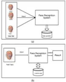
Fig 1: Overview of general face recognition system (a) training phase (b) After completion of training phase
A. Steps In Face Recognition System
The generic face recognition system consist of three main processing steps as shown in fig.2. i) FACE DETECTION separating face
region from input image or video. ii) FEATURE EXTARCTION in which it identifies and extract features of the submitted images. iii) RECOGNISING FACE IMAGE by matching input image against the faces in database.
[image:3.612.250.358.112.245.2]Fig 2: Configuration of a face recognition system
The face recognition system is classified into two types i) Global approaches-the whole image serves as a feature vector. It’s also analysing the statistical properties of the face based on a large set of training images ii) Feature based face recognition-a number of control points are extracted and used for classification.
B. Super Resolution
Super Resolution (SR) is a technique that enhances the resolution of an imaging system and increase imaging sensors performance. [4] The standard SR method consists of sub pixel registration, interpolating the missing values by overlaying the LR images on an HR grid. There are many approaches for image enhancement have been proposed, many realistic problems have not been solved satisfactorily. When an image is improved or up sampled many times, blur or mosaic phenomena tend to occur thus decreasing the quality of the image. In real time applications like wireless surveillance, the resolution of obtained video/image is quite low due to limited bandwidth requirement in transmission. For solving these problems, the Super Resolution techniques are developed. This approach is used to construct a HR from a single or multiple LR images. When explaining in terms of pixels, the size of HR image is larger than LR image and then the improved methods can magnify the LR image and increase image details, making the magnified image close to the HR origin image. These techniques have become a popular research topic due to its broad applications in face recognition and surveillance.
FACE DETECTION
FEATURE EXTARCTION
FACE RECOGNITION
III. DESIGN METHODOLOGY
Fig 3: Design methodology
This is a simple image reading and resizing module written in MATLAB. It reads two images from database for comparison. One of which is High Resolution (HR) image and another having noise image (i.e.) Low Resolution (LR) image. The two image files will generate a test input file which we can use as input to Verilog module. Text file is obtained as output.
IV. RELATIONSHIP LEARNING BASED SUPER RESOLUTION ALGORITHM
There are several algorithms that exist to convert a Low Resolution image into a High Resolution image. But these methods fail when a Very Low resolution image is used. Hence an RLSR algorithm is proposed. The Fig.4 shows the block diagram of the RSRL algorithm.
Fig 4: Block diagram of RLSR
A. Training Phase
The training phase consists of two major steps, namely, linearity clustering and co relation learning. In the first step, a clustering algorithm is proposed as a pre-processing step. After clustering, the Very Low Resolution (VLR)-High Resolution (HR) image pairs in each cluster are nearly linear, i.e., the co-relation can be approximately represented by a matrix. In the second step, the relationship mapping from the VLR to the HR face image spaces within the cluster is determined.
B. Data Base
All the images are taken against a blazing homogenous background with the subjects in an upright, frontal position. The files are in JPEG format. The size of each image is 64×48 pixels, with 256 grey levels per pixel. Both male and female subjects are present in this resource database. To create the Very Low Resolution (VLR) image corresponding to each of these High Resolution (HR) images, the VLR images are resized to 16×12 pixels. To create the Very Low Resolution (VLR) image complementary to each of these High Resolution (HR) images, the HR images are resized to 64×48 pixels. A test image pair is shown below Fig5.
Training data Testing image Linearity clustering RLSR learning Classifying to one cluster
Technology (IJRASET)
[image:5.612.214.392.216.462.2]511
Fig 5: HR-VLR image pairC. Linearity Clustering
Clustering means assigning a set of data points (objects) into groups. The objects in the same cluster are more similar to each other than to those in the other clusters. Trust upon the dataset the appropriate clustering algorithm and parameter settings is done. A linearity clustering algorithm is proposed to confirm that the clustered training image pairs have a linear relationship.
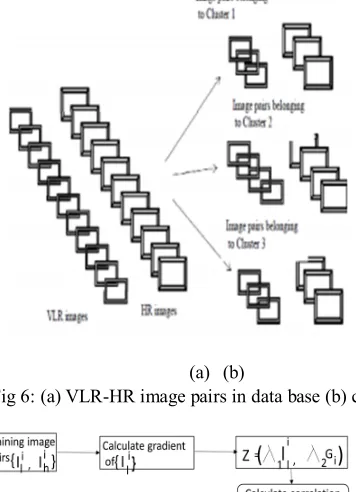
(a) (b)
[image:5.612.195.409.307.580.2](b) Fig 6: (a) VLR-HR image pairs in data base (b) clustered images
Fig 7: Steps involved in clustering algorithm
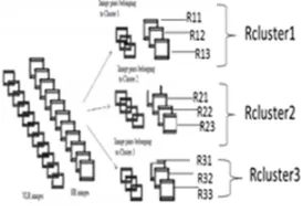
Fig 8: (a).VLR-HR image pairs (b) clustered image pairs used to Generate R cluster
In RLSR algorithm, cluster holds the training image pairs (VLR-HR). Assume the relationship R be the mapping between VLR to HR with in the cluster, then Ihi = R (Ili). After assuming R then apply R to the VLR image to recover the HR image. A matrix R is used after clustering to represent relationship mapping R. The relationship operator R can be derived as R = inverse (LR)*HR. From this, the relationship matrix corresponding to each of the image pair is determined. The linear clustering aids in obtaining a unique relationship operator for each of the cluster. So, the relationship operators of the images in a particular cluster are extracted. The relationship operator corresponding each cluster-Rcluster is selected such that reconstruction error is minimum. Fig.8 gives a pictorial representation of how the unique relationship operator - Rcluster, corresponding to each cluster is obtained. The straight forward method for this is minimising the reconstruction error. The reconstruction error is measured in the HR image space by the data constraint e R.
eR(Ih) = ||Ih – Ih’|| minR 1/N Σ || Ihi– RIli||
Utilizing the above two equations in the learning process ensures that the Rcluster chosen incurs minimum reconstruction error. Another mechanism used to choose the optimum Rcluster is by computing the average of the relationship operators belonging to each cluster
3.4 Testing Phase
The dimensions of the test image is 16×12 pixels with 256 gray levels. For testing VLR image is given as a test image. G test is used for calculating the gradient of the image. The parameter of the clustering algorithm used in the training phase is gradient. To classify the VLR image into the appropriate cluster ‘i’, G test is used. After identifying the cluster ‘i’, for input testing image the corresponding R cluster-i is applied.
[image:6.612.240.377.77.173.2]
Fig 9: Sample images
[image:6.612.236.375.483.720.2]Technology (IJRASET)
513
Images in Cluster 3
Fig 10: (a) VLR test image (b) Reconstructed Output HR image
V. RESULTS
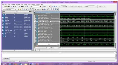
[image:7.612.200.411.272.709.2]The results in MATLAB the training images in the Data base are grouped into 3 clusters and outputs are connected to verliog file. Then linearity based clustering is shown in modelsim simulator. Fig11 Shows the simulation result for linearity clustering. Fig 12 shows the reconstructed HR image in matlab window.
Fig 11: Simulation result for Clustering based on linearity
Fig 12: Input and Output images
4.1 Device utilization summary
PART UTILIZATION Number of slice LUTs 2693 out of 19200 14%
Number used as memory 1532 out of 5120 30%
Number of slice registers 320 out of 19200 1.6%
[image:7.612.207.404.282.391.2]Minimum input arrival time before clock: 2.163ns
Maximum output required time after clock: 4.013ns
Minimum period: 4.831ns (maximum frequency 207.009MHz)
VI. CONCLUSION
Rectification for the VLR problem in face recognition was discussed by using RLSR algorithm. This RLSR method was implemented for good visual quality applications. The design and architecture of enhanced face detection for VLR images was designed in Verilog and implemented on FPGA. The main advantage is a new data constraint set was developed for measuring the error in the HR image. In the experimental results it shows that the number of clusters in the algorithm increases, the results obtained are with good visual quality. But, as the number of clusters in this approach increases the number of images in the database will increase it causes overlearning (learning of redundant data). The experimental result consume less time in averaging relationships in each cluster than the relationship operator got by minimizing the reconstruction error.
REFERENCES
[1] Cristbal, G., E. Gil, F. Sroubek, J. Flusser and C. Miravetet al., 2008. Super resolution imaging: A survey of current techniques. Proceedings of the Advanced Signal Processing Algorithms, Architectures, Implementations XVIII, Sep. 3-3, SPIE, San Diego ,California, USA., pp 0C1- 0C18. DOI:10.1117/12.797302
[2] Glasner, D., S. Bagon and M. Irani, 2009. Super resolution from a single image. Proceedings in IEEE 12thi
international conference in Computer Vision,Sept. 29-Oct. 2, IEEE Xplore press, Kyoto, pp: 349-356.
[3] Jia K. and S.Gong,2008. Generalised face super resolution IEEEtrans. Image Process.,17;;873- 886 DOI:10.1109/ TIP.2008.922421 Qin,F.Q., X.H. He and W.Wu, 2009.
[4] Video superresolution reconstruction based on sub pixel Registration and iterative back projection. J. Electr. Imag., 18: 1-16. DOI: 10.1117/1.3091936 [5] SenthilSingh, C. and M. Manikandan, 2012. Design and Implementation of an FPGA-based real-time very low resolution face recognition system. [6] Int. J. Adv.Inform. Sci. Technol., 7: 59-65. Zou, W.W.W. and P.C. Yuen, 2010Learning the relationship between high and low resolution images in kernel
space for face super resolution.
[7] Proceedings of International Conference in Pattern Recognition, Aug. 23-26, IEEE Xplore Press, Istanbul, pp: 1152-1155. DOI: 10.1109/ICPR.2010.288 [8] Zou, W.W.W. and P.C. Yuen Very low resolution face recognition problem. IEEE Trans.
ImageProcess.,i21:327-40. DOI:10.1109/TIP.2011.2162423