Study and Analysis of Bandwidth
Enhancement using Z-U-T-S Shape Structures
in an Integrated CPW Fed Printed Monopole
Antenna
Dr. Sumit Kumar Gupta1, Harish kumar jangam2, Nipun Sharma3
1
Assistant Professor, Parishkar College of Global Excellence ,Jaipur,
2,3,
Research Scholar SunRise University, Jaipur
Abstract: sA dual band co-planar waveguide fed Z-U-T-S shaped monopole antenna is proposed. The antenna is fabricated on an h = 1.6mm FR4 epoxy substrate with dielectric constant εr = 4.3 and loss tangent tan δ = 0.008. The size of the radiating
element is 15.9 X 11.4 mm2
I. INTRODUCTION
In recent years, many dual-band antennas have been developed to meet the increasing demand for a modern wireless communication device which is capable of integrating more than one communication standard into a single system. Various types of antenna designs for this have been reported. Horng-Dean Chen and Hong-Twu Chen (2004) proposed a dual-frequency design of coplanar waveguide (CPW)-fed monopole antenna achieved a fractional bandwidth of 4.3% and 5.6% in band I and band II with a gain of 4dBi.The antenna size is 20.2 x 26.3 mm2. Shaoqiu Xiao (2005) designed an ultralow-profile microstrip antenna with 10 loaded slots and inset feed structure is proposed and achieved a fractional bandwidth of 5.4% and 7.8% in band I and band II with a gain of
3dBi. The antenna size is 19.6 x 22.5 mm2. Deshmukh and Kumar (2006) proposed a broadband slotted S-shaped microstrip antenna
with a fractional bandwidth of 8.2% and 9.6% The gain is around 3.5 dBi and the antenna size is 18.5 x 22.5mm2. Alkanhal et al
(2007) designed a novel compact dual-band reconfigurable square-ring microstrip antenna and achieved a bandwidth of 10.26% and 8.6%.The gain of the antenna is 4dBi and the antenna size is 18.5 x 22.5mm2.
In this paper, a novel antenna design with Z-U-T-S shaped structures is presented which not only has good dual band operation performance, but also a simple structure and compact size. By adjusting the length of the different shaped structures the resonant frequency can be tuned and a good impedance match can be obtained. The asymmetric ground plane is used to enhance the bandwidth. The detailed design and experimental results for the proposed antenna are demonstrated.
The main features of Z-U-T-S shaped antenna design are
A. Resonant length of each structure
B. Tuning stub and an asymmetric ground plane
Step 2
Step 8
Step 11
Step 12
Figure 1 Progress of the Geometry of the proposed antenna and its response
In this chapter, six separate monopole antennas are integrated with good response. The simulation is done for individual antennas and the respective return loss is obtained. Later these antennas are integrated one by one and the simulation is done for each stage and the respective return loss is obtained.
Step 1 shows the monopole antenna .It is designed for 4.5GHz .It has the length of 16.64mm and the width of 0.5 mm. One resonant mode is created at 4.5GHz with the return loss value of -18dB.The bandwidth obtained is 4.2 to 4.7GHz.
In step 2, the straight monopole is folded in the form of U shaped of
at 4.5GHz now the input impedance of the antenna is changed. When we two arms of the U shaped antenna is equal, the current distribution is uniform in both the arms. Later the right arm of the U shaped antenna is reduced 20% of the left arm to give good return loss value and to improve bandwidth.
The shaped monopole is shown in step 3 has a narrow bandwidth
sonant mode is created at 4.6GHz.
A stepped T shaped structure is formed in step 4 is designed at a
frequency 4.8 GHz having length 15 .Initially the T shaped structure is designed without any
steps. Then we discontinuity is created in the form of steps with different length and width to improve the bandwidth The S shaped structure is designed for a frequency of 6.3GHz having length 8mm in step5.
In step 6, the vertical shaped monopole antenna is designed for a frequency of 6.5GHz and one resonant mode is created at the
same frequency.
The length is 7 mm close to t 6.5 GHz.
In step 7 the horizontal monopole having a length 13mm is designed for a frequency 6.1GHz.One resonant mode is created at
6.1 GHz.
In step 8 both and asymmetric U shaped monopole antennas are integrated and one resonant frequency is obtained at 4.5 GHz.
The resonant frequency is increased due to the variation of impedance. Hence the height and width of the ground plane is adjusted to bring the resonant frequency to operate at 4.5 GHz.
In step 9 another stepped T shaped monopole is added along with this combined antenna. One additional resonance is created at 4.8GHz. The resonance frequency is now shifted to compensate this one two stubs are placed at each ground plane. The 1st band is obtained with a frequency range 4.2GHz to 4.9GHz.
In step 10 the shaped monopole is added in the right arm of the
asymmetric shaped antenna and one resonant mode is created in the second band at a frequency 6.3 GHz. Now the resonant frequency is shifted for the first band. There is a step like arrangement is done in the ground plane to improve the bandwidth. In step 11 the vertical shaped structure is added hence the resonant frequency is affected. One resonant mode is created at 6.5GHz with good return loss value of -25dB.
In step 12 the horizontal shaped structure is added serially with the existing antenna and one resonant mode is created at
6.1GHz.For these three monopoles the total length is 3 .
The measured -10 dB return loss bandwidth is from 4.5 to 5.2GHz (14.43%) with respect to the centre frequency at 4.8 GHz and 6 to 6.7 GHz
(11.02%) with respect to the centre frequency at 6.5 GHz for the second Band to satisfy the wireless communication applications.
II. ANTENNA DESIGN
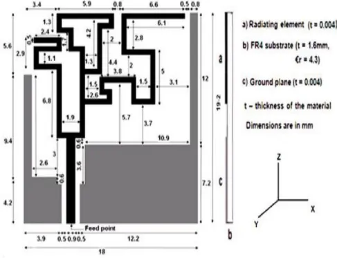
The geometry of the proposed antenna is illustrated in Figure 2. The antenna is fabricated on an h = 1.6mm FR4 epoxy substrate
with r = 4.3 The size of the radiating element is 15.9 X 11.4 mm2.
The proposed antenna with Co-planar Waveguide (CPW) feed is shown in Figure 3.3. The U shaped branch of length 16.5mm of length 6.8mm combined together to
form a monopole antenna of length 23.3mm which is 0/4 at a frequency 4.6 GHz. The stepped T shaped branch having
paths, one resonant path is in the monopole antenna and another one is in the stepped T shaped branch, thereby supports two resonances at 4.8 and 4.6 GHz which are close to each other and hence these two frequencies can be combined results in wide bandwidth.
To further enhance the bandwidth in the upper frequency region, three more 0/4 branches namely,
shaped,horizontal asymmetrical u shaped and vertical asymmetrical shaped branches, shown by L4, L5 and L6 in Figure 3.4, supports three resonances close to 6.1, 6.3 and 6.5 GHz. The total length (L4+L5+L6) of the resonant path for these
0/4 at a frequency 6.2 GHz.
To increase the resonant path, stepped T shaped branch, extended shaped branch d
branch and vertical are used. Due to increase in the current path length, the resonance
[image:9.612.65.552.297.670.2]frequency is decreased and hence the bandwidth is increased. Asymmetrical structures provide wide bandwidth. The widths for the strips are chosen to be 0.5 mm. Also note that, very different from a conventional one, the CPW structure of the proposed design has two asymmetrical finite ground planes, one L shaped ground with vertical dimensions of 0.8 x 12 mm2 and a horizontal section with dimensions of 7.2 x 12.2 mm and another L shaped ground including a vertical section with dimensions of 0.8 mm x 9.4 mm and a horizontal section with dimensions of 4.2 mm x 3.9 mm. This ground plane provides best impedance matching and enhance the bandwidth. In this geometry, IE3D software is used to design the antenna.
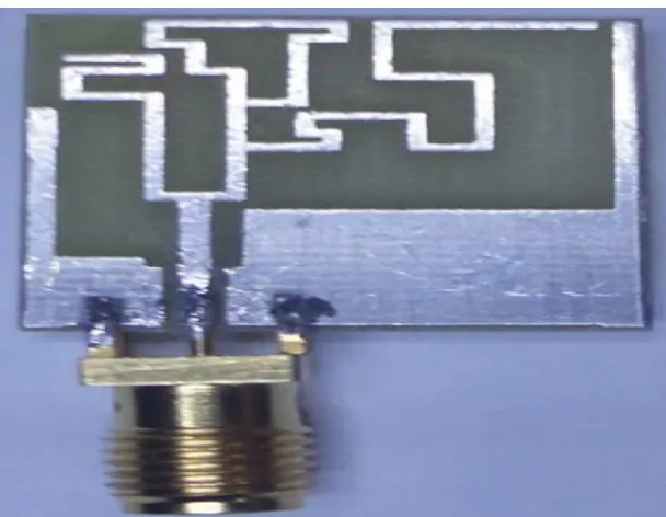
Figure 3 Fabricated Z-U-T-S shaped antenna
[image:10.612.81.520.344.729.2]III. BANDWIDTH ENHANCEMENT
Figure 3 shows the parameters of the Z-U-T-S shaped structure. Here all the shape of the structures are designed close 0/4 length with their corresponding operating frequencies. Various important parameters are studied to design and enhance the impedance bandwidth. All the design parameters are selected after several simulations only. The most sensitive parameters are L1, L6 and Vg. These parameters affect the impedance bandwidth. In order to determine the impedance bandwidth accurately, one parameter is varied at a time and other parameters are kept constant.
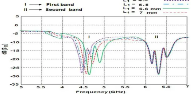
A. Effect of Varying the Length L1: When the length L1 for the branch is varied from 4.5 to 7 mm, the
resonant frequency is shifted from 4.4 to 4.8GHz and correspondingly the bandwidth is increased as shown in Figure 3.5 of both U and stepped T shaped branches. In the I band, the first and second resonance modes are changed whereas in the second band, the resonant modes are not changed. When the length L1 increases, the impedance bandwidth at the lower operating frequency increases whereas the upper operating frequency remains almost unchanged. After 6.6 mm, the bandwidth starts decreasing. Hence, the optimized value 6.6mm is selected.
Figure 5 (a) Simulated graph for various Length L1
B. Effect of Varying the Length L6: Figure .5 (b) shows the effects of thereturn loss for various length L6
branch. The total length of L4 and L5 is also affected, because all these branches are connected in series. It can be seen that the variations of the
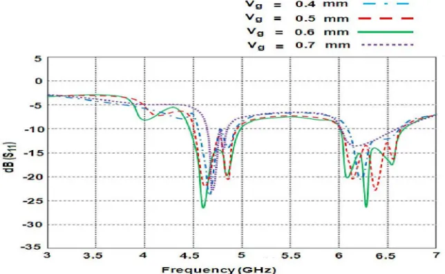
[image:11.612.129.434.273.424.2] [image:11.612.69.512.564.702.2]C. Effect of Varying the Vertical Gap Vg: The vertical gap Vg is variedbetween the top edge of the ground plane and the bottom edge of the radiating element. Figure 3.5 (c) shows the variations of Vg for different values. It can be seen that, in both first and second bands, the resonant frequencies are shifted. In the first band, the resonant frequencies are not affected severely whereas in the second band, for higher value of capacitance, the resonant frequency is vanished. Therefore, the parameter Vg is selected to be 0.6mm to have a wide bandwidth and relatively good matching.
Figure 5 (c) Simulated graph for various Vg
Return Loss
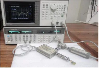
[image:12.612.125.447.174.372.2]The simulated and measured results for -10 dB return loss are plotted in Figure 3.6. The measured -10 dB return loss bandwidth is from 4.5 to 5.2GHz (14.43%) with respect to the centre frequency at 4.8 GHz and 6 to 6.7 GHz (11.02%) with respect to the centre frequency at 6.5 GHz. The measurement of return loss and VSWR are carried out with HP 8757D Scalar Network Analyzer. A relative good agreement in between measurement and simulation can be observed. Figure 7 shows the photograph of the Return loss measurement set up. The related Return loss and VSWR measurement graphs are shown in Figures from 8 (a) to 8 (d).
[image:12.612.125.512.488.704.2]Figure 8 (b) Return loss measurement at 6.5 GHz
[image:14.612.129.498.98.316.2] [image:14.612.124.495.352.676.2]Figure 8 (d) SWR measurement at 3 GHz
IV. CURRENT DISTRIBUTION
The simulated surface current distribution at two different frequencies 4.6 GHz and 6.3 GHz are shown in Figure .9(a) & 39 (b). At
4.6GHz, the current in the shaped branch, the current is maximum
[image:15.612.108.509.95.303.2] [image:15.612.141.464.433.703.2]Figure 9 (b) Surface Current Distributions at 6.3GHz
At 6.3 GHz, the maximum current flow occurs in three different resonators as shown in Figure .9 (b). It is noticed that, in all the three resonators the current is maximum at the starting point shown in red colour and minimum at the ending point shown in blue colour. The overall current length for these three resonators monopole is approximately 3 0//4. In most of the places in the Ground plane weak current distributions are seen.
V. RADIATION PATTERN
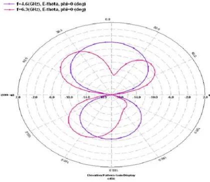
The simulated radiation patterns are shown in Figure 10 (a) and 10 (b). It is observed that at 4.6 GHz, the antenna has a dipole like radiation pattern and it is not symmetrical in the E plane. Not symmetrical pattern due to variation of current in the Z-U shaped and stepped T shaped branches. At 6.3 GHz, the antenna has monopole like radiation pattern and it is not symmetrical one. In the H-plane, the antenna has nearly omnidirectional pattern at 4.6 GHz and 6.3 GHz as shown in Figure 10 (b). Measurements of radiation patterns for a Z-U-T-S shaped antenna are taken in an anechoic chamber as shown in Figure 11.
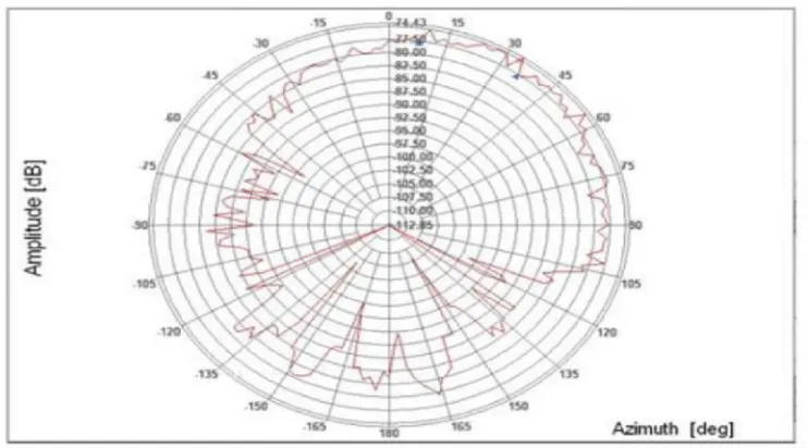
The measured radiation pattern are shown for E-plane and H-plane at 4.6 GHz as shown in Figures 12 (a) and 12 (b). It is note that, there are some discrepancies between measurements and simulations in radiation patterns for both the planes. In the actual measurement, as the ground plane size is small, a few leakage currents may distribute along the external conductor of the SMA connector and may affect the radiation patterns.
[image:16.612.131.510.97.256.2] [image:16.612.214.424.500.682.2]Figure 10 (b) Simulated Azimuth Pattern (E phi at 4.6 GHz & 6.3 GHz)
[image:17.612.118.491.285.469.2] [image:17.612.119.490.489.695.2]Figure 12 (b) Measured H-plane (XY) pattern at 4.6 GHz
VI. GAIN
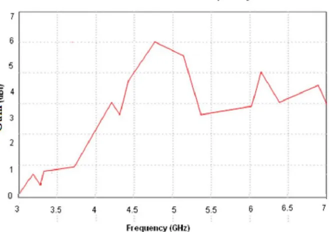
[image:18.612.154.461.88.311.2]Figure 13 shows the characteristics of the gain for the Z-U-T-S shaped antenna. The peak gain is around 6 dBi at 4.6 GHz. The simulated peak gain at the lower operating frequencies varies from 0 to 6 dBi, and at the higher operating frequencies it varies from 2 to 4 dBi
Figure 13 Gain Characteristic of a Z-U-T-S shaped antenna
VII. CONCLUSION
[image:18.612.132.461.407.639.2]REFERENCES [1] FCC News, FCC 02-48, Feb. 14, 2002.
[2] Lin, D.-B., I.-T. Tang, and M.-Y. Tsou, “A compact UWB antenna with CPW-fed,” Microwave and Optical Technology Letters, Vol. 49, No. 3, 564–567, 2007.
[3] Liu, W.-C. and W.-R. Chen, “CPW-fed compact meandered patch antenna for dual-band operation,” Electronics Letters, Vol. 40, No. 18, 1094–1095, 2004. Progress In Electromagnetics Research C, Vol. 54, 2014 115
[4] Kim, T. H. and D. C. Park, “CPW-fed compact monopole antenna for dual-band WLAN applications,” Electronics Letters, Vol. 41, No. 6, 291–293, 2005. [5] Lee, S. H., J. K. Park, and J. N. Lee, “A novel CPW-fed ultra-wideband antenna design,” Microwave and Optical Technology Letters, Vol. 44, No. 5, 393–396,
2005.
[6] Liu, W.-C., C.-M. Wu, and N.-C. Chu, “A compact CPW-fed slotted patch antenna for dual-band operation,” IEEE Antennas and Wireless Propagation Letters, Vol. 9, 110–113, 2010.
[7] De Cos, M. E., M. Mantash, A.-C. Tarot, and F. Las Heras, “Dual-band coplanar waveguide-fed smiling monopole antenna for WiFi and 4G long-term evolution applications,” IET Microwaves, Antennas & Propagation, Vol. 7, No. 9, 777–782, 2013.
[8] Thomas, K. G. and M. Sreenivasan, “Compact CPW-fed dual-band antenna,” Electronics Letters, Vol. 46, No. 1, 13–14, 2010.
[9] Li, Y. S., X. D. Yang, C. Y. Liu, and T. Jiang, “Compact CPW-fed ultra-wideband antenna with dual band-notched characteristics,” Electronics Letters, Vol. 46, No. 14, 967–968, 2010.
[10] Chu, Q.-X. and Y.-Y. Yang, “A compact ultrawideband antenna with 3.4/5.5 GHz dual bandnotched characteristics,” IEEE Transactions on Antennas and Propagation, Vol. 56, No. 12, 3637– 3644, 2008.
[11] Zehforoosh, Y. and T. Sedghi, “A CPW-fed printed antenna with band notched function using an M-shaped slot,” Microwave and Optical Technology Letters, Vol. 56, No. 5, 1088–1092, 2014.
[12] Zheng, Z.-A. and Q.-X. Chu, “Compact CPW-fed UWB antenna with dual band-notched characteristics,” Progress In Electromagnetics Research Letters, Vol. 11, 83–91, 2009.
[13] Krishna, D. D., M. Gopikrishna, C. K. Anandan, P. Mohanan, and K. Vasudevan, “CPW-fed Koch fractal slot antenna for WLAN/WiMAX applications,” IEEE Antennas and Wireless Propagation Letters, Vol. 7, 389–392, 2008.
[14] Zhao, G., F.-S. Zhang, Y. Song, Z.-B. Weng, and Y.-C. Jiao, “Compact ring monopole antenna with double meander lines for 2.4/5 GHz dual-band operation,” Progress In Electromagnetics Research, Vol. 72, 187–194, 2014.