Systems Reference Library
IBM 2701 Data Adapter Unit
Principles of Operation
This manual provides information concerning the operation of the
IBM 2701 Data Adapter Unit. The manual is divided into three
sections.
The first section gives a general description of the 2701, includ-ing: the terminals operating with the 2701, the functional organi-zation of the 2701, the special features on the 2701, and various configurations of the 2701.
The second section describes the operation of the 2701 with the System/360. Subjects discussed here include communication line addressing, multiplexor and selector channel operation, and
I/O instructions concerning the 2701.
The third section covers the 2701's transmission adapters. A complete description on the operation of each adapter is made here. This description includes transmit and receive operation sequences, status and sense bytes, and the polling and addressing of the terminals.
Copies of this and other IBM publications can be obtained through IBM Branch Offices. Address comments concerning the contents of this publication to:
Form A22-6864-0 Page Revised 7/1/65 By TNL N27-2901
Contents
Introduction . . . .. 5
Functional Sections ... 5
Transmission Interface Converter (XIC) ... 5
I
Transmission Adapter (XA) ... 5Special Features ... . . 5
Expansion Feature ... . . . .. 5
Expanded Capability Feature .. . . .. 6
Second Channel Interface Feature . . . .. 6
Automatic Call Feature .. . . .. 6
2701 Configuration . . . .. 7
Operational Functions . . . .. 9
Line Addressing . . . .. 9
2701- Channel Operation. . . . .. 9
Multiplexor Channel Operation . . . .. 9
Selector Channel Operation . . . .. 9
System Considerations . . . .. 9
I/ 0 Instructions .. . . .. 10
Start I/O . . . .. 11
Test I/O ... 11
Halt I/O ... 11
Programming Considerations . . 12
Transmisssion Adapters. . . . . .. 13
Communication - Start/Stop Adapters . . . . . .. 13
Programming Considerations . . . 13
Commands ... 13
Adapter Operation . . . .. 15
Special Features . . . .. 17
Diagnostics . . . .. 17
Automatic Answering . . . 17
IBM Terminal Adapter - Type I .. . . 18
IBM Terminal Adapter - Type II ... 22
IBM Terminal Adapter - Type III ... " 23 IBM Telegraph Adapter ... 23.1 Telegraph Adapter - Type 1. ... 23.1 Telegraph Adapter - Type II ... 26
\Vorld Trade Telegraph Adapter ... " 28 Communication - Synchronous Adapter . . . .. 29
I
Data Acquisition and Control Adapters ... 29.1 Parallel Data Adapter ... 29.1 Contact Sense Adapter ... . . . .. 36I
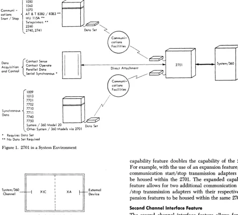
The IBM 2701 Data Adapter Unit greatly expands the
input/ output capabilities of the IBM System/360
( frontispiece). The 2701 provides for the connection and control of the information How of a variety of re-mote and local external devices with an IBM System/
360 (Figure 1). These devices are divided into three types:
COMMUNICATIONS - START/STOP
IBM 1030 Data Collection System IBM 1050 Data Communication System IBM 1060 Data Communication System IBM 1070 Process Communication System
AT&T 83B2/83B3 Type Selective Calling Terminals
Western Union Plan 115A Terminals Common Carrier TWX Stations (8-level code) European Teleprinters (WT attachment)
2848 Display Controls with 2260 Display Stations. 2740 or 2741 (without interrupt feature)
Communications Terminal
COMMUNICATIONS - SYNCHRONOUS
IBM 1009 Data Transmission Unit IBM 1013 Card Transmission Terminal
IBM 7701 Nlagnetic Tape Transmission Terminal IBM 7702 Magnetic Tape Transmission Terminal IBM 7710 Data Communication Unit
IBM 7711 Data Communication Unit IBM 7740 Communication Control System IBM 7750 Programmed Transmission Control IBM System/360 with similarly equipped 2701's
DATA ACQUISITION AND CONTROL
Parallel Data Devices Contact Sense Terminals Contact Operate Terminals Serial Synchronous Terminals
The IBM 2701 can be attached to either the
multi-plexor or selector channel of the System/360. With the second channel interface feature, the 2701 can be at-tached to another channel on the same processor (multiplexor or selector) or to a channel on another processor. This means that different terminal devices on the 2701 can operate via the multiplexor channel or the selector channel. However, once a terminal device is assigned to a channel, it will operate only via this channel.
Functional Sections
The 2701 Data Adapter Unit provides for the on-line attachment of various input/output devices to any of
Form A22-6864-0 Page Revised 7/1/65 By TNL N27-2901
Introduction
the System/360 processors. All necessary bit-byte, word-byte conversion, data control, and interface matching is accomplished by the two functional sec-tions of the 2701: the transmission interface converter
( XIC) and the transmission adapter (XA).
The XIC and XA operate as a couple which provides
a single complete path for the operation of the term-inal devices with the channel (Figure 2). In a 2701 which has more than one XIC-XA couple, the XIC is
logically the same for each couple; the XA changes,
according to the type of terminal devices attached. A minimum 2701 configuration contains one XIC-XA
couple. With the use of special features, the 2701 can have up to three more XIC-XA couples. See "2701
Con-figuration" section and Figure 3.
Transmission Interface Converter (XIC)
The XIC operates with the I/O interface; stores the
status, sense, and command bytes; decodes the trans-mission adapter I/O address; develops and checks the
parity of the data transfers with the I/O channel;
re-sponds to specific control unit commands; and operates with the transmission adapter.
Transmission Adapter (XA)
The transmission adapter contains the circuits neces-sary to perform the functions associated with a given external device or class of terminal devices, such as interface control, parity decoding, character and char-acter sequence recognition, data buffering and byte conversion, and status and sense byte generation.
Special Features
The special features fall into two major classifications. There are some special features on the 2701 which affect all the transmission adapters, whereas others are on a particular transmission adapter and affect only that adapter. Only the former will be discussed in this section. The special features for the transmission adapter will be found in the following sections, in which the various transmission adapters are discussed.
Expansion Feature
This feature provides an additional XIC function for
the attachment of another XIC-XA couple. The only
circuitry in common with the first XIC-XA couple is
the power supplies and the I/O channel interface
drivers, terminators, and receivers. This sharing of the interface circuitry allows additional XIC-XA couples to
Form A22-6864-0 Page Revised 7/1165 By TNL N27-2901
1030 1050 1060 Communi - 1070
cations AT & T 83B2 / 83B3 ** Stort / Stop WU 115A **
Teleprinte~ ** 2260
2740,2741 Data Set
2701 ... _ _ ~ System/360 Acquisition Contact Operate
{
Contact Sense Data
and Control Parallel Data Direct Attachment
Synchronous Data
Serial Synchronous *
' 1009 1013 7701 7702 7710 7711 7740 7750
System / 360 Model 20 Doto Set Other System / 360 Models via 2701
* Requires Data Set ** No Data Set Required
• Figure 1. 2701 in a System Environment
System/360 _ I I
Channel 11
II
r
s~~,-em~o-n
'-flU I II I.,. \1
XIC
T
I I
I
I
I
:
XA
Single XIC-XA Couple
XIC XA
XIC XA
Two XIC-XA Couples
Figure 2. 2701 Functional Sections
+
ExtemolDevice
JExtemol
1\ Device
be added without decreasing the total number of addi-tional control units allowable on the 110 channeL With
the expanded capability feature, up to three expansion features are available in the same 2701.
Expanded Capabiiity Feature
The expanded capability feature provides for addi-tional XIC-XA couples within the 2701. The expanded
6
capability feature doubles the capability of the 2701. For example, with the use of an expansion feature, two communication start/stop transmission adapters may be housed within the 2701. The expanded capability feature allows for two additional communication start /stop transmission adapters with their respective ex-pansion features to be housed within the same 2701.
Second Channel Interface Feature
The second channel interface feature allows for one or more of the XIC-XA couples to be operated on a
second channel from the other couple in the 2701. This second channel may be another channel on the same processor (for example, the 2701 basic unit connected to the multiplexor channel and the second channel interface feature connected to the selector channel) or to a channel on a second processor. The extreme would
be to connect the second channel interface feature
to the same channel as the 2701 basic unit, but this would serve no useful purpose and would unneces-sarily reduce the number of additional control units on that channel from seven to six. Once an XIC-XA
couple is assigned to one or the other channel, it will operate only on that channel; ,there is no capability to switch from one to the other.
Auiomaiic Call Feaiure (ACF)
[image:6.620.41.521.66.499.2]allows the terminal device to be dialed, under program control over common carrier switched dial networks. The ACF almost falls into the category of special features
which affeot only the particular transmission adapter; however, the automatic call feature affects the total number of XIC-XA couples allowable in the 2701 and is,
therefore, discussed here. See the configuration section for further details.
2701 Configuration
The 2701 configuration is made up of the following units and features:
2701 basic unit Transmission adapter Expansion feature
[image:7.615.73.381.423.719.2]Expanded capability feature Second channel interface feature
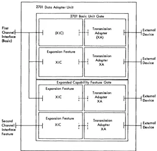
Figure 3 shows the maximum 2701 configuration, using all of the above units and features. This configuration has four transmission adapters, two per gate. As will be shown below, this configuration is not possible with every transmission adapter.
The 2701 basic unit supplies the frame, covers, power, a logic gate, and a transmission interface con-verter (XIC). To complete the XIC-XA couple, a
trans-mission adapter must be obtained. The other units and
2701 Data Adapter Unit
2701 Basic Unit Gate
I
I Fint Channel Interfac (Basic)
e
r--I
(XIC)
1
Expansion Feature
H
XICI I Transmission
1- -1 Adapter 1 1
(XA)
Transmission
I I Adapter
.... - -I I 1
XA
Expanded Capability Feature Gate
I Second Channel Interfac Feature el
' - -
-I
~
I
Expansion Feature
XIC
Expansion Feature XIC
• Figure 3. Maximum 2701 Configuration
Transmission ~- -~ Adapter
1 I
XA
Transmission
~ I
Adapter
1-1
1 I XA
I
1
I
1
I
1
I
1
Form A22-6864-0 Page Revised 7/1/6.5
By TNL N27-2901
features are described in the transmission adapter and the special features sections.
Some 2701 transmission adapters require more physi-cal space than others in the 2701 frame. The use of these adapters restricts the number of the other XIC-XA
couples housed within the same 2701. As an aid in specifying the configuration capabilities of the 2701, the transmission adapters have been grouped into three categories (Figure 4).
The 2701 basic unit gate can accommodate up to two category I adapters, one category II adapter, or up to
two category III adapters. Adapters from different
categories cannot be housed on the same gate.
The use of the expanded capability feature gate doubles the number of transmission adapters the 2701 can accommodate. Again, up to two category I adapters,
one category II adapter, or up to two category III
adapters can be accommodated on this gate. The trans-mission adapters on the expanded capability feature gate can be from the same or a different category as the adapters on the 2701 basic unit gate.
Expansion features must be obtained for each trans-mission adapter after the first. As mentioned earlier, the automatic call feature, when ordered on the com-munications start/stop adapters, reduces by one the allowable number of category I adapters. The
auto-matic call feature, when ordered with the
communica-I I
I
1
J
I
I
I
External Device
External Device
External Device
External Device
Form A22-6864-0 Page Revised 7/1/65 By TNL N27 -2901
Transmission Adopters
I
IBM Terminal Adopter Type I
r - - - -I IBM line Adopter Feature I- - -
---I Automatic Call Feature
I
IBM Terminal Adopter Type II
r -I IBM Line Adopter Feature
I
IBM Telegraph Adopter
I
Telegraph Adatper Type r
I
Telegraph Adopter Type n
r -
A.;t~~t~Call
Fe~t~r;-I
World Trade Telegraph Adopter
I
Synchronous Dota Adopter Type I
[
=D~c{ ~o~ni" 10~f~c~ ~~:~~ : Internol Clock Feature1---: Automatic Call Feature
I
IBM Terminal Adapter Type m
j---r---l
Contact Sen.e Adapter* ~ 48
[~jie~i;~~u;
=
=~=:~96
i
Extension Feature, 2nd 97 144I
Contact Operate Adapter*
Serial Synchranous Adapter*
i -
-SYncPatte~ F;atur;-L - - - t - - - . - J
-o~~~~ ~ 0 0 0 0
o ...
... l I " ) M
-~~NM'<t
~2121212~
r---,
.. ", ,,": ,,1,,"1 .;: Parallel Data Adopter
~: ~ I ~I ~ I ~I -0 Timeout Feature
4:.U: 1U:~u.: I u:1,f
t-
"3 ;;;
4-E)(te~~-Y
E151515151_ - F01';;; .;;;1.;;; ';;;1 61--..I.--_ _ ea_t_ur_e_5 _ _ ---I
o c lei c I c cu
;;; I!x I !)(I!)( I ! ) ( I . E _ I
-~ I Parallel Dota Adopter
'
=0...00"
t:
1"1n
~ ~!-J
I
[~i;~~ ~~;~-~ ~
I
I
I U to i. txtensionI
. _ I --reatures _
* See TNl N27-2901
• Figure 4. Categories of 2701 Transmission Adapters
8
~I
~I
~I
tion synchronous adapter, does not have this restrict-tion.
When more than one automatic call feature are required, this restriction applies only with the first.
For example, the first communication - start/stop adapter (category I) with an automatic call feature completes a gate. The expanded capability feature must be obtained in order to add more adapters. With the expanded capability feature, in this case, two ad-ditional adapters from catgory I can be attached, and
both adapters can also have the ACF. (The example
could just as well have shown one category II or two
category III adapters on the expanded capability gate.
The second channel interface feature connects an
XIC-XA couple on the expanded capability feature gate
to a second channel. When more than one XIC-XA couple
are ordered on this gate, one or both couples can be connected to the second channel. For example, refer back to Figure 3. In the figure one XIC-XA couple on
the expanded capability feature gate is shown con-nected to the second channel, and the other is shown connected to the same channel as the XIC-XA couples
on the 2701 basic unit gate. Both XIC-XA couples on
the expanded capability feature gate could just as well have been shown connected to the second channel. When the second channel interface feature is not obtained, all the XIC-XA couples housed within the
Line Addressing
To the IBM System/360, the 2701 appears as a control
unit. Each 2701 may house up to four XIC-XA couples. Up to eight 2701's can be attached to each I/O channel, with each 2701 taking the place of one control unit otherwise attachable to that I/O interface. Each XIC-XA couple within a 2701 is identified by a unique I/O address that is specified by an II-bit binary number. This number is specified by the address field of the start I/O instruction; the three high-order bits of the field specify the channel; the next eight bits specify the terminal device attached to the 2701. For more information concerning I/O unit addressing, see "Input! Output Operation," IBM System/360 Principles of
Operation, Form A22-6821.
NOTE: Even when more than one terminal device is connected to an XIC-XA couple, only one I/O address exists. Addressing beyond this must be accomplished by other means. See transmission adapter section for specific details.
270J
-Channel Operation
The 2701 connects to and operates with the multi-plexor or selector channel via the I/O interface. This interface consists of byte-buses for commands, ad-dresses, data, or status; channel interlock controls; and interface scanning signals. The scanning signals and interlocks establish priorities among the different 2701's and other control units attached to the I/O channel and among the XIC-XA couples within each 2701.
On either the multiplexor or selector channel, an I/O operation is initiated by a program command given by the channel and accepted by the control unit. The I/O device addressed cannot be addressed again until the 2701 presents the terminating status to the channel.
The 2701 operation on the multiplexor channel differs slightly from its operation on the selector chan-nel. Each type of channel operation is discussed below. Multiplexor Channel Operation
When connected to a multiplexor channel, the 2701 can operate in one of three modes: byte, multiple hyte, or burst.
Byte i\lode: The 2701 releases the I/O channel after initial selection, after transferring each byte of data, and prior to presenting the terminating status.
j\lultiple Byte: The 2701 releases the I/O channel after initial selection and after each data word is
Operational Functions
transferred. (A data word is defined here as the num-ber of bytt;s buffered in the transmission adapter.) The data word length varies, for different transmission adapters, from two to eighteen bytes. The channel is also released after the transfer of the last data word and prior to the presentation of the terminating status. See "System Considerations" for details.
Burst Mode: The 2701 maintains control of the multiplexor channel from initial selection until after the presentation of terminating status. Burst mode may be obtained as a wiring option on the XIC. Neither the transmission adapter nor the channel has any control over the selection of one or the other modes of opera-tion once the XIC is so wired.
If the XIC is wired for burst mode, the mode of opera-tion is the burst mode. If the XIC is not so wired, the transmission adapter has the ability to force the opera-tion to be in the multiple byte mode. The capability to force multiple byte mode is designed into only those adapters that have registers to buffer multiple bytes of data. If the transmission adapter is so designed, opera-tion will be in the byte mode. See helow.
ADAPTER MODE WIRE OPTION RESUL TING MODE
Byte Nonnal Byte
Multiple byte Normal Multiple byte
Byte Burst Burst
Multiple byte Burst Burst
Selector Channel Operation
The selector channel always operates in burst mode. This mode is forced by the selector channel itself, and the 2701 has no control over it. In burst mode, the 2701 will not release the channel from initial command selection until the entire operation is completed and the terminating status is presented.
System Considerations
The meaning and usage of the byte, multiple byte, and burst modes for multiplexor channel operations are explained here. The system designer can specify the operation to be either burst mode or normal (non-burst) mode. The system designer has no way of specifying between byte and burst mode. "7hile on the multiplexor channel, with the XIC set for normal mode, the transmission adapter determines whether the oper-ation will be in byte or multiple byte mode. A buffered transmission adapter, that is, an adapter which can immediately transfer multiple bytes of data with the
channel, operates in the multiple byte mode on the multiplexor channel. Adapters which are not buffered and must obtain each byte of data from the terminal device operate in byte mode.
The main difference among the three modes of operation is the amount of interference the program and the channel encounter. Multiple byte mode in-creases the length of the program and the channel interference per data transfer over the byte mode, but significantly decreases the over-all program and chan-nel interference by decreasing the number of selec-tions required per message. For operaselec-tions on the multiplexor channel, each time the channel performs a data transfer with a control unit, it must access the subchannel control word of the particular I/O adapter from storage; therefore, each access interferes with the program. The interference due to the actual data trans-fer is minimal compared to the access intertrans-ference. It can be seen, therefore, that by reducing the number of accesses required per message, the processor inter-ference can also be reduced. As an example, the pro-cessor interference for a six-byte burst on the multi-plexor channel of the Model 30 is about one fourth the interference that would occur from transferring six bytes in the byte mode. The channel is unavailable to other devices for a longer time period when operating in the multiple byte mode than in the byte mode. How-ever, the total over-all interference is less. The longer time period of unavailability may be intolerable for real-time device requirements. Therefore, channel in-terference must be considered. Channel inin-terference is measured from a control unit standpoint. The system designer has to know the maximum length of time that the control unit must wait between two successive data transfers. For proper operation of the control unit, the maximum time should be such that the prob-ability of losing data is minimal. When determining the maximum channel interference caused by any control unit, the time to do command chaining with a transfer in channel operation must be comnared to the time required to perform the longest data
~r
status transfer. The longer of the two is the maximum inter-ference.For 2701 XIC-XA couples which operates in byte
mode, the time needed to perform the command chain-ing operation will be longer than the time required for a data transfer. For XIC-XA couples that operate
in the multiple byte on burst mode, the time required for the data transfer may exceed the time required to command chain. This time should be calculated for each case.
The multiple byte mode, as opposed to the burst mode, reduces the maximum channel interference by releasing the channel after accepting the initial status
10
and prior to presenting the terminating status. To further reduce channel interference, transmission adapters which have data word lengths greater than six bytes have the capability of being started at six-byte intervals. For example, a transmission adapter with 18 bytes in its data word can, under program command, be started at the first byte, the 7th byte, or the 13th byte. In this manner, if an I8-byte trans-mission presents too great an interference to the other control units on the channel, the programmer can limit the length of the multiple byte operation by the byte count in the channel command word. As a further example, consider a command with a byte count equal to six. When the 2701 attempts the transfer of the 7th byte, the channel will reject the transfer and signal the control unit to stop the operation. The 2701 will release the channel and at its next opportunity present the terminating status. The program can now cause a new command to restart the data transfer at the 7th byte (and later at the 13th byte).
The burst mode of operation has the 2701 maintain control of the multiplexor channel from initial selec-tion until after the presentaselec-tion of the terminating status. When operating on the multiplexor channel, burst mode should be used with the greatest of caution because it presents the greatest channel interference. It should only be used with transmission adapters which end after presenting each data word. When burst mode is used with transmission adapters, which present several data words prior to ending or when it is used with unbuffered adapters, processor interference must also be studied; for example, on the multiplexor chan-nels of Models 30 and 40, there is 100 percent pro-cessor interference when the data transfer is in the burst mode.
110 Instructions
The System/360 operates with the 2701 through the start I/O, test I/O, and halt I/O instructions.
An I/O instruction executed by the CPU causes initial
command selection and the transfer of a command byte to the addressed XIC-XA couple of the 2701.
Com-mand chaining within the channel also causes selec-tion and transfer of a command byte.
The command byte is decoded by both the XIC and
the XA. A command which is successfully decoded by
the XIC is operated on independent of the XA. An Xil.~
decoded command is operated on by both the XIC
and XA. A command which is not successfully decoded
by either the XIC or XA is rejected by the unit check
bit being presented in the status b),te.
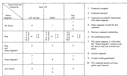
The status byte returned to the channel in response to a command selection indicates the 2701's condition
and acceptance or rejection of the command. Figure 5 presents the meaning of each possible status response for each of the 110 instructions.
Start 1/0
There are many commands which may be issued with the start 110 instruction or as a result of command
chaining. Where the XIC-XA couple has neither a
pre-vious command nor has outstanding status (status bits which have been set by either the XIC or the XA, but
have not yet been accepted by the channel), and a valid start 1/0 command is decoded, all zero status
will be returned to the channel. This indicates that the command has been accepted.
The sense and 110 no-op commands are the only
commands resulting from a start 110 instruction or a
command chain that is decoded and operated on by
the XIC. (The other valid commands are decoded
within the XA.) Each XA type accepts a different set
of commands. Commands with the same bit structure may be defined differently for each type of adapter; therefore, only the sense command will be discussed here. The other commands will be discussed in later sections.
After completing transfer of the all-zero status byte, which indicates the 2701's acceptance of the sense command, the XIC transfers the sense byte to the
chan-nel and then presents terminating status with the de-vice end and channel end bits on.
~
ICommands Start I/O
Status
Response I/O No-Op Other
All Zeros 4 1
,i}
2}
Busy or
{
~
5{
~
6 or
10
Busy 2 2
and
Status Register*
7
Status Register* 1 4
3
Unit Check 4 2
8
* The "Status Register" is defined here as an outstanding status within a control unit excluding the busy bit (that is, up to 7 bits).
Figure 5. Status Responses to Instructions and Commands
j}
Test I/O
1
3 6
or
4
1
3
4
Form A22-6864-0 Page Revised 10/29/64 By TNL N22-0160-0
The definition of the bits within the sense byte de-pends upon which adapter is being used with the
XIC. The sense bits are defined in the following sections,
which cover the various adapters; however, bits 0 and 2 are reserved for the XIC:
Bit 0 - Command Reject.
This bit is set during an initial selection or com-mand chain sequence when a comcom-mand byte is not successfully decoded by either the XIC or the XA. Bit 2 - Bus Out Check.
This bit is set whenever the XIC detects a parity error on the transfer of a byte from the channel over the bus-out lines.
The register within the XIC that holds the sense byte
is reset by the XIC-XA couple's acceptance of a start 1/0
command other than sense and 1/0 No-Op.
Test 1/0
Through the test 110 instruction, the CPU can
address-ably obtain the current status byte from any XIC-XA
couple.
D pon decoding the test 110 command, the XIC
pre-sents the contents of the status register. The test 1/0
command ends with this status transfer. The accept-ance of this command does not reset the sense register in the XIC.
Halt I/O
When operating on a command and upon detection of a halt 1/0, the XIC-XA couple will not transfer any
further data, and will be "busy" to any further
com-l. Command accepted 2. Command re jected
3. Command successfully terminated with status response
4. Status response inval id for th is command
5. Previous command outstanding
{
~
6. No outstanding status7. This status response is valid when the "Status Register" contains only the device end and channel end status
8. Invalid command 9. A reset is being performed
10. This command should not have gotten past channel
[image:11.618.71.514.435.702.2]Form A22-6864-0 Page Revised 10/29/64 By TNL N22-0160-0
mands until terminating status is accepted by the channel. Terminating status is presented to the channel as soon as possible; otherwise the XIC-XA couple will be
immediately available.
Programming Considerations
From a programming standpoint, the 2701 appears as a number of individual devices (one to four). When an operation or a sequence of operations is to be performed, the programmer prepares a list of one or more channel command words (channel program) in main storage. The channel command word signifies: 1. The command (operation) to be performed: write, dial, read, etc.
2. The number of bytes in the record.
3. The initial address in main storage where the data should be placed when receiving, or the address of the first byte to be transmitted when sending.
4. Channel Hag information indicating that another channel command word is to be executed when the current operation is terminated.
When the channel command words have been
12
formed, the programmer specifies the channel and ad-dress of the XIC-XA couple. The execution of a start
110 instruction causes the command, count, data
ad-dress, and control information to be stored in a speci-fied subchannel in the multiplexor channel or in the register in the selector channel. The channel then se-lects the 2701's XIC-XA couple, and presents the
com-mand to it. The 2701 accepts the comcom-mand if valid. The channel then indicates successful or unsuccessful execution of the start 110 instruction to the
program-mer. Once the command has been accepted by the channel and the 2701, the CPU program is unaware
of the continuance of the operation until all the data has been received or transmitted, or until the channel needs program intervention to perform functions such as dynamic storage allocation. Because the channel contains all the necessary information pertaining to the current operation, data transfer between main storage and the XlC-XA couple can be overlapped with CPU processing. The extent of the overlap varies,
The transmission adapter (XA) provides for the
con-nection and operation of remote and local devices with the System/360. The 2701 obtains its personality from the transmission adapter it houses. Each trans-mission adapter provides for the 'attachment and operation of a particular device or class of devices with the 2701. The transmission adapter contains the circuitry and logic for the control of a terminal de-vice, the buffering of the data How, the decoding of the program commands, and the connection to and operation with the XIC and the I/O channel.
Transmission adapters used in the 2701 are classi-fied into one of three types: communications-start/stop adapters, communications synchronous adapters, and data acquisition and control adapters.
Communication-Start /Stop Adapters
Start/stop adapters for the 2701 include the following:
IBM Terminal Adapter-Type I, IBM Terminal
Adapter-I
Type II, IBM Terminal Adapter-Type III, TelegraphAdapter-Type I, Telegraph Adapter-Type II, IBM
Tele-graph Adapter, and the World Trade TeleTele-graph Adapter. The operation of the 2701 start/stop adapters with the remote terminals requires various types of communications facilities and data sets (Figure 6). Fig-ures 7 and 8 list the 2701 start/stop adapters and the terminals that may be operated with each. Also listed are the communications facilities and data sets re-quired for the operation.
Programming Considerations
For those communication-start/stop terminals (1030, 1050, 1060, 1070, etc.) which can operate with both the 2701 and 2702, the operation programs used are identical. However, this compatibility does NOT extend
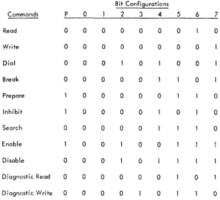
to diagnostic programs. Commands
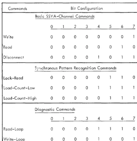
The communications-start/stop adapters decode and execute the commands listed below. Some cOplmands,
2701
Data Adapter Unit
Interface
2701
Dato Set
Communication Facility
Form A22-6864-0 Page Revised 7/1/65 By TNL N27-2901
Transmission Adapters
such as read, write, and inhibit, are valid for all adap-ters; other commands, such as dial and search, are valid only for certain ones. The commands used by each type of adapter are listed in the section for that adapter. Binary representation of each command is given in Figure 9.
Read: This command causes bytes to be transferred from the communication line to the channel at a data rate equal to that of the communication line.
Write: This command causes bytes to be transferred from the channel to the communication line at a data rate equal to that of the communication line.
Inhibit: This command performs the read operation but inhibits the time-out function. Otherwise, the operation proceeds as if a read command had been issued.
Break: This command causes the 2701 to transmit continuous space signals to the line. Bytes transferred from the channel to the addressed unit must all be zeros. To provide control over the length of a space signal, a byte count must be specified by the program.
Prepare: This command can be used in a contention type communications system to indicate (to the cpu) that data are arriving. When a valid start bit is de-tected while the XIC-XA couple is operating upon a
prepare command, the command is terminated with a device end, channel end status. Prepare can be command-chained to a normal read command. No data transfer occurs with this command, and timeout is not active during its execution.
Search: This command causes the 2701 to react as though a read command has been issued, but data are not transferred to the channel. The data line is moni-tored for an EOT (end of transmission). Line timeout
is active during the execution of this command. This command is valid only for the Telegraph Adapter-Type I.
Terminal Data Set
Terminal
Figure 6. Terminal Connection via Data Sets and Communications Facilities
Form A22-6864-0 Page Revised 7/1/65 By TNL N27-2901
Terminal 1050 Data Communication Syst"m
105! Contra! Unit Modell or 2
1051 Control Unit Model 1 or 2 with Telellraph Attachment '7873
1051 Control Unit Model I or 2 with line Adopter '4790
1060 Data Communication System 1061 Cont,OflJnftl\iIodel I or
I-1061 Control Unit Model I or 2 with line Aclapter '4790
1030 Data Collection ~stem
I OJ I A Input Station
I OJ I A Input Station
with Cammon Carrier Adapter '2068
~7~0~;~:t~rJn,::,I=sl System
r--1071 Control Unit Modell with Line Adopter 14792
1071 Control Unit Model·2
1071 Control Unit Model 2 with line Adapter '4793
2740,2741 Communications Terminal
I
I
I
2710/27 .. 1
I with IBM Une Adopter
I I
Communication Facility
Common Cor,i", Switched Telephone Network
Common Carrier Switched (1.50 loud. Tel.typewrlt., E"chonge (TWX)
N.twor~
Cammon Carrl.r lea .. ct !'rlvate line Tel.phon. Servlc. W .... m Union ClaM 0 (l1IO loud) Channel
Telephon. Company Sch.dule 3A Data Channel. (150 loud) Telephon. Compony Schedule J or We.tem Union Cia .. C Channels (62.5 me Neut,al SllInel)
..
Common Ca",er lea .. d POrlva'e relephone Service
Westem Union Clan 0 (180 laud) Channel
telephon. Company Schedule 3A Data Channell (150 laud)
..
..
Common Carrier leased Four-Wire Full Duple" Private relephone Servlc.
West.m Union Clall E Channel
Common Carrier leased Private line Tel'phone Service W •• tern Union Clall 0 (180 Baud) Chann.1
..
Common Carrier le .. sed Four-Wlra Full Duple" ~Ivate Telephone Service
Wlltern Union Cia .. E ChQnnel
..
Cammon Carrier Switched Telephon. Network Common Co mer Switched
TWX Nerwo';' (i5O 8aud) Weltem Union Clau 0 Data Channels (ISO /laud) Telephon. Company Schedule 3A Channels (1.50 loud) Common Co,rl., lea"d "rlvate Line Telephone Service Western Union Clau E Chonnels Privately Owned Communieotlan
facUlties I I
Terminal Data Set • 2701 Data Set •
West"m E!ectric Western Electric 103A2 103A2 We.tem Electric Wellem Electric
103Al 103AI We.tem ~Iectric Wettern Electric
1031'2 1031'2 w.st.m Union Westem Union Data Set 11 72'A Data Set 1172'A
An appropriate chann.1 termination provided by the Telephone Company Not Required Not Required
Not R.qulred Not Requlr.d
Western Electric Weltem Electric 103F2 103F2 Wlltem Union Wettem Union Data Set 11725A Dato Set II 72'A
An appropriate channel termination provided by the Telephone Company Not Required
Not Required
Western Electric 20201 Western Union
1601 A
Weltern Electric 103F Western Union Data Set I 172SA Not Required
Westem Electric 20201 Weltern Union
1601 A Not Required
Western Electric 103A2 Westem Electric iOJAi Western Union II72SA i
Not Required
Not Required
Weltern Electric 20201 Wlltern Union
1601 A
We.tern Electric I03F Westem Union Data Set 11725A
Not Required
Weltern Electric 20201 Wettern Union
1601 A Not Required
Westem Electric 103A2 Western Electric 'V~"'" Western Union IlllSA An appropriate channel termination provided by the Telephone Company Weltern Electric Westem Electric
103F2 103F2 Westem Union Westem Union
160IA 160IA Not ~.qulr.d Not Required
I
Spe"d
134.49 loud
14.8 Char/Sec
75.0 loud •. J3 Char /Sec 134.49 laud 1 .... Chor/Sec
134.49 loud 14.1 Char/Sec
134.49 laud 14.' Char/Sec
600 laud
60 Char/Sec 600 laud 60 Char/Sec
134.49 Baud 14.' Char/SIc 134.49 laud 14.8 Char/Sec 600 laue! 66.6 Char/Sec 600 laud 66.6 Char/SIc 134.49 Baud 14.11 Char/Sec
• Figure 7. Attachable Terminals and Communications Facilities for Domestic Use (Communica-tions-Start/Stop Adapters)
14
2701 Adopte"
IBM Terminal Adapter Type I '4645
IBM Tel"graph Adopter
laM Terminal Adopter Type I '4645
11M line Adapter '4636
laM Terminal Adopter Type I '4645
11M Terminal Adapter Type I '4645
11M line Adapter '4636
11M Terminal Adapter Type " '4648
11M line Adapter '4637
11M Terminal Adapter Type " '4648
IBM Terminal Adapter Type I '4645
11M Terminal Adapter Type I '4645
IBM line Adapter '4636
IBM Terminal Aclapter Type I '4646
IBM terminal Adapter Type I '4646
IBM line Adopter '4637
tiM Terminal Adapter Type 1
Terminal Communication Facility Terminal Data Set • 2701 Data Set * Speed 2848 Control Unit Common Corrier Western We.tern 1200 80ud
2260 Di.play Station Leased Private line Electric Electric 120 Char/See Telephone ServIce 20201 20201
Western Western 2400 laud Electric Electric 2.0 Char/Sec 201Bl 20181
We.tem Union 2121A 2121A 1200 laud
Clem E 120 Char/Sec
Dota Channel.
~, (Teletypewriter Exchange)
Models 33 and 35 TWX Western Electric We.tem Electric a-level Code Terminal. Common Carrier Switched 103AI 103AI at 110 laud
150 bps TWX Netwarko Only
Other Terminals
AT & T 8382/8383 Telephone Compony Schedule I Not Required. Not Required. .5.5 laud Terminal. Channels (., 8oud) 62.5 ma 62.5 ma
Neutral Neutral dc loop: dc loop: Tip Negative, Tip Negative,
Telephone Compony Schedule 2 Ring Pooitive Ring Positive 56.9toud Channeh (57 8oud)
Telephone Compony Schedule 3 74.2 toud Channels (75 Baud)
Western Union Plan 115 A Western Union Not Required. Not Required. 45.5 Baud Terminals Closs A Channel
62.5 mO 62.5 rna
Western Union Clos. B Channel. Neutral Neutral 56.9 Baud (57 Baud) dc loop: dc loop:
Tip Negative, Tip Negative, Ring Positive Ring Positive
Western Union Closs C Channels 7 •• 2 80ud (75 Baud)
*Data Sets are those indicated or their equivalent.
** Common Carrier leased Private line Telephone Facilities conforming to SRl Manual A24-3435 or Privately Owned Two Wire Communication for limited Distance line Adopter II •
• Figure 7. Attachable Terminals and Communications Facilities for Domestic Use (Communica-tions - Start/Stop Adapters) (continued)
Form A22-6864-0 Page Added 7/1/65
By TNL N27 -2901
2701 Adapter< IBM Terminal Adapter Type /II
'.656
IBM Terminal Adopter Type 1/1 '.657 IBM terminal Adapter Type III '.656
Telegraph Adopter Type II '7885
Telegraph Adapter Type I
'7860
Telegraph Adopter Type I '7861
Telegraph Adopter Type I '7862
Telegraph Adopter Type I '7860
Telegraph Adopter Type I '7861
Telegraph Adapter Type I '7862
Terminal Communication Foell ity Terminal Doto Set 1 050 and 1060 Data Communication Systems and 2740/2741 Communications Terminals
1051 Control Unit Modell or 2 Common Carrier Leased Private 111M 3976 1061 Control Unit Model I or 2 line Telephone Service
2740/2741 Communications Terminal 1051 Control Un.t Modell or 2
1061 Caritrol Unit Model lor 2 Not Required
2740/2741 Commu~lcations Terminal ** with line Adopter 4790
1070 Procell Communication System
1071 Control Unit Model I Common Carrier leased Private 111M 3976 line Telephone Service
1071 Control Unit Modell
with line Adopter '4792
..
Not Required 1071 Control Un.t Model l Common Carrier leased Four - Wire IBM 3917 Model 1Private line Telephone Servke
1071 Control Unit MOdel 2
with line Adopter '4793 Not Required
..
1030 Doto Collection System 1031A Input Station
Not Required
..
1031 A Input Station Common Carrier leased Four - Wire 111M 39f7 Model I with Common Carrier Adopter '2068 Private Une Telephone Service
- - - ----~~--
~-2~8 Display Control Common Carrier leased Private IBM 3977 Model 1 2260 Display Stallon line Telephone Service
World Trade Teleprinters
-W T Teleprinter
---r
Common Carrier Private lineTelegraph Circuits (Double- Not Required Current Telegraph line,)
!Teleprinter Common Carrier Private Line
Telegraph Circuits (Slngle- Not Required Current Telegraph lines)
*. Common Corrier Leased Private line Telephone Facilities conforming to SRL Manual A24-J435 or Privately Owned Two Wire Communication for limited Distance line Adopter II •
2701 Data Set Speed
IBM 3976 134.4 Baud 14.8 Char/Sec
Not Required
IBM 3976 134.4 Baud 14.8 Char/Sec
Not Required
IBM 3977 Model 1 600.0 Baud 66.6 Char/Sec
Not Required
600 llaud Not Required
60 Chor/Sec 111M 3977 Model 1
IBM 3977 Model I 1200 Baud
120 Char/Sec
IBM 39(5 Model 11 50 Baud
75 Baud
IBM 3945 Model 12 50 loud
75 8aud
Form A22-6864-0 Page Revised 7/1/65 By TNL N27 -2901
2701 Adopters
111M Terminal Adopter Type i
'4645
IBM Terminal Adopter Type I '4645
IBM LIne Adopter '4636
IBM Terminal Adopter Type I '4645
IBM Terminal Adopter Type I '4645
IB~~; Adopter
IBM Terminal Adopter Type I '4646
111M Terminal Adopter Type I '4646
IBM line Adopter '4637
IBM Terminal Adapter Type II '4648
11M line Adopter '4637
11M Terminal Adopter Type II '4648
11M Terminal Adopter Type III '4656
W T Telegraph Adopter
W T Telegraph Adopter
W T Telegraph Adopter
W T Telegraph Adopter
• Figure 8. Attachable Terminals and Communications Facilities for \VT Use (Communications - Start/Stop Adapters)
Enable: This command conditions the 2701 to auto- munication line is isolated and does not receive this matically answer incoming calls. This has meaning data. This command is ended either by the XA
rec-only when operating on a dial network. ognizing a terminating sequence of data or by a stop
Disable: This command deconditions the effect of signal issued by the channel.
the enable command. The 2701 will disconnect a call Diagnostic Read: This command presents the byte
( if one is in operation) and will not answer any further of data stored in the diagnostic register to the channel.
incoming calls. This condition exists until an enable The comunication line is isolated and no data occuring command is given. on the line will be recognized by the XIC-XA couple.
Dial: This command will be accepted by the 2701
only when it has the automatic call feature. This com- Adapter Operation
mand enables the automatic call feature to obtain dial Receive Operation
digits from the processor. The dial command is ended when the call is either successfully completed or abandoned.
Diagnostic Write: This command sends data to a
diagnostic register. If more than one byte are trans-ferred, only the last byte remains stored. The
com-The receive operation is initiated when the XIC-XA
couple accepts a read type command (read, inhibit, search) from the channel. Upon detection of a start bit, the XA prepares to receive a character. The
char-acter, which is received one bit at a time, is assembled in a data register. When a full character has been
Bit Configurations
P 0 3 4 5 6 7
Read o 0 0 0 0 0 0 0
Write o 0 0 0 0 0 0 0
Dial o 0 0 0 0 0
Break o 0 0 0 0 0
Prepare 0 0 0 0 0 0
Inhibit 0 0 0 0 0 0
Search o 0 0 0 0 0
Enable 0 0 0 0
Disable o 0 0 0
Diagnostic Read 0 0 0 0 0 0 0
Diagnostic Write 0 0 0 0 0 0
Note: Byte positions 0 and 1 must contain zeros; however, these posi-tions are ignored by the basic 2701 Data Adapter Unit. Figure 9. Communications - Start/Stop Adapter Commands
sembled, the XA checks for special characters, checks
for VRC, assembles the LRC (where applicable), and
requests a data transfer to the channel. The channel has a minimum 2.1 bit time, which prevents losing a character. This response time is determined with the worst possible receive distortion. The stop bit is checked for, and, unless some terminating status con-dition occurs, the XA prepares to receive the next
character.
Line Time-Out
A 28-second timeout between data characters is per-formed when the XA is operating on a read type
com-mand other than inhibit. The timeout is used to prevent a communication line or terminal failure from going undetected. The timeout is started when the stop bit is received, and terminated when the next start is detected. If the timeout elapses, the command is term-inated, and the channel is notified of this occurrence through the status and sense bytes. Some transmission adapters also require a short timeout.
Transmit Operation
The transmit operation is initiated by the acceptance of a write command by a XIC-XA couple. The XA accepts
a character from the channel and transmits it a bit at a time over the communications facilities. The XA in-serts the start and stop bits, checks for special char-acters, accumulates and transmits the LRC character
(where applicable) and inserts shift characters (where applicable) .
U niess some terminating condition has occurred, the XIC-XA couple will request a data transfer after the
last data bit is sent to the communications line. '''hen
16
the data code requires one stop bit, there are 1.3 bit times for the channel to respond without elongating the stop bit time. When the data code requires two stop bits, the time is a 2.3 bit time. Although it de-creases the overall data rate, an elongated stop bit is a normal occurrence for start/stop transmission schemes.
Status Byte
The following terminating statuses may be presented by the communications-start/stop adapter to the channel:
Device End, Channel End Status: Indicates that
the current command has been brought to a normal end and the unit is free to accept another command.
Device End, Channel End, and Unit Exception Status: Indicates that the current command has been
brought to a successful conclusion and EaT (end of
transmission) has been received, or a no response to a poll has been detected.
Device End, Channel End, and Unit Check Status:
Indicates that the current command has been ended with an unusual condition. A sense command must be issued to the addressed unit to further define these conditions.
Device End, Channel End, Unit Exception, and Unit Check Status: Indicates that the current command has
been ended by unusual conditions and an EaT or a no
response to a poll has been received. A sense command must be issued to the addressed unit to further define these conditions.
Sense Byte Definition
The sense byte is transferred to the channel during the sense operation; definition of the bits as they are sent to System/360 storage is given below:
() Command reject* 1 Intervention required 2 Bus out check*
3 Equipment check
4 Data check
5 Overrun
6 Receiving
7 Timeout
I ntervention Required is set when the following
conditions exist:
1. The attached data set, where applicable, has power off or is in test mode.
2. An attached automatic calling unit, where ap-plicable, has power off.
3. Continuous space signal has been received on a given communications line for more than one
character.
Equipment Check is set when a halt I/O is detected
during a service cycle.
Data Check is set during receive operations if:
1. At stop time, the receive data sample is a space signal.
[image:17.615.42.266.62.266.2]2. If a parity or cyclic check error is detected. (Dur-ing transmit operations, this bit is set if an echo check is detected at the relay interface of a telegraph line adapter. )
Overrun is set during receive operations if a byte is lost because data service could not be obtained in time.
Receivina is set whenever the addressed unit is en-t:>
gaged in receiving data. The automatic call feature sets this bit when a dial command is issued to a line that is currently "off-hook."
Timeout is set when the communications line
time-out has elapsed. The automatic call feature sets this bit to indicate that the dial operation has not been successfully completed.
Special Features
Automatic Call Feature
This feature enables the 2701 to originate calls on a
I
switched dial network by dialing through a Western Electric Automatic Calling Unit, or equivalent. This feature is not needed or used for handling the auto-matic answering of calls on a switched network. The automatic call feature can operate with only certain types of transmission adapters and certain types of terminals attached to those adapters. Therefore, the capability for the automatic call feature will be dis-cussed in the sections covering the specific transmis-sion adapters and the terminals.To perform a dial operation, the programmer sets up the dialing number, one digit per byte, in an out-going message. The digit is represented in binary code in bits 4, 5, 6, and 7 of the byte. He then issues a dial command (a bit configuration is shown in Figure 9), with a byte count equal to the number of digits to be dialed. The 2701, when it accepts the dial
com-I
mand, presents the digits to the automatic calling unitfor dialing. vVhen the call has been answered, the 2701 presents the device end, channel end status to the channel. Command chaining then occurs to a read or write command, depending upon the opera-tion. If, for some reason, the call cannot be com-pleted, the 2701 presents the device end, channel end, and unit check status with the timeout bit set in the sense byte.
ISM Line Adapter Feature
The IBM Line Adapter Feature is available with only
certain communications-start/stop adapters, and with only some of the terminals that operate with these adapters. The capability to operate with the IBM Line
Adapter is stated in the sections covering the specific transmission adapters. The IBM Line Adapter is a
modem that provides for the attachment of the 2701 transmission adapter to customer-owned private tele-phone lines for distances up to 8 wire miles,
conform-Form A22-6864-0 Page Revised 7/1/65 By TNL N27-2901
ing to IBM 1030 Data Collection System Physical Planning, Form A24-3021.
Diagnostics
2701 start/stop adapters each have a diagnostic regis-ter located on the 2701's side of the line drivers or relays that operate with the communication facilities. Through a diagnostic write command, data can be sent through the 2701's XIC-XA couple to the diagnostic
register. The diagnostic register holds the start bit, the data bits, and the stop bit(s). If multiple bytes are transmitted under this command, only the last byte will remain stored in the register. Through a diagnostic read command, the contents of this register are sent back to storage for checking. The 2701 oper-ates on this byte as though it were being received from the communication line. The start bit is checked; the data character is checked for special character; the shift bit, if applicable, is added; the stop bit is checked; and the character is transferred to the channel.
The use of the diagnostic commands allows a major portion of the 2701 circuitry to be checked out. The clocks, counters, registers, serializers, deserializers, etc. can be checked. Some of the decoding capabilities can be checked and the LRC generation circuitry can
be checked. For example, with an IBM Terminal Adap-ter-Type I, the diagnostic write command can be
used to transmit multiple bytes of data, the last byte being the EOB character. As will be explained in the
section describing the IBM Terminal Adapter-Type I,
the recognition of the EOB character causes the
trans-mission adapter to transmit the EOB followed by the LRC character and then presents terminating status to
the channel. The last character transmitted is the LRC
character, which will reside in the diagnostic register. A diagnostic read command can then be given to bring the LRC character to storage for checking. On both a
diagnostic read and diagnostic write operation, the communication lines are degated. In this manner, no data will be transferred to or from the
communica-ti~n
lines. There are other techniques peculiar to eachtype of adapter, such as special character generation, which is not discussed.
Automatic Answering
Automatic answering of incoming calls, a standard feature on the IBM Terminal Adapter-Type I and the
Telegraph Adapter-Type II, allows the programmer
to control the answering of incoming calls. When the programmer desires to allow the answering of in-coming calls, he issues an enable command to the 2701. The SLI (suppress length indication) Hag is set
in the associated channel command word. When a
Form A22-6R64-0 Page Revised 7/116,5 By T~L ~27-2901
call is answered, the enable command is ended, with
the XIC-XA couple setting the device end, channel
end status, Command chaining may be applied to either a write or a read command, depending upon the application, \ Vhen conditions change and the pro-grammer no longer desires to accept incoming calls, a halt I/O command is given to the XIC-XA couple
which causes the device end, channel end status to be presented and the data set prevented from answering any further incoming calls. Once an en-able command is given, the data set remains condi-tioned to answer calls until either a halt I/O or disable
command is issued.
IBM Terminal Adapter-Type I
The IB;\f Terminal Adapter-Type I enables the 2701
to control data transfer between an IBM System/360
and the following terminals: IBM 1050, 1060, 1070,
2740, and 2741 (without interrupt feature) terminals at 14,8 characters per second (134.49 bps) or the IBM
1070 at 66,6 characters per second (600 bps.) Figures 7 and 8 illustrates the data sets and communications facilities required for each of the above terminals operating at different speeds. The IBM Terminal
Adap-ter-Type I matches the line control required for
ter-minal operation with the I/O channel using System/360
programming capabilities. Polling and addressing re-sponses, VRC (vertical redundancy checking) and LRC
(longitudinal redundancy check), special character recognition, and shifted character operations are all handled by the XA to minimize system interference.
Commands
The IB~I Terminal Adapter-Type I decodes and
ex-cutes the following commands: read, write, inhibit, enable, disable, prepare, diagnostic read, and diagnos-tic write, The dial command is also valid for this adapter when it has the automatic call feature. The functions of these commands are explained under the communication-start/stop adapters.
Special Features
Two special features are available for the IBM Terminal
Adapter-Type I:
The automatic call feature is obtainable with the IBM
Terminal Adapter-Type I only when operating with the
IBM 1050 Terminal.
The IB~I Line A.daptcr Fcature is obtainable with the IBM Terminal Adapter-Type I only when operating
with the 1050 or 1070 terminals.
Adapter Operation
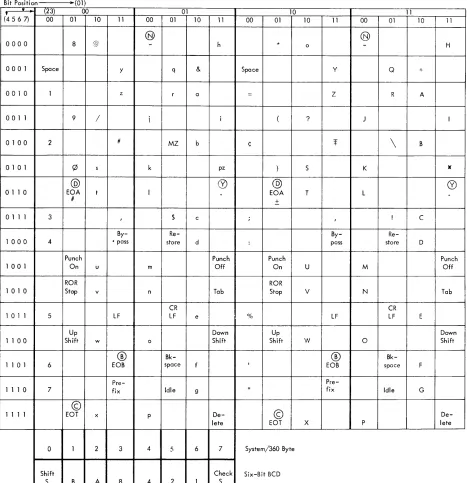
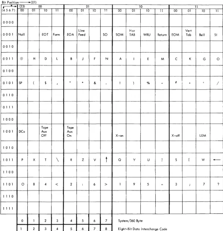
Character Set: The transmission code between the 2701 and the 1050, 1060, 1070, 2740, and 2741 ter-minals is six-bit RCD. The relationship hetween the 2701
18
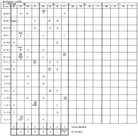
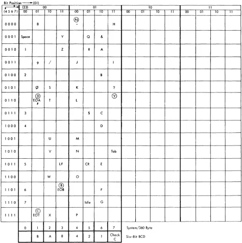
and the I/O interface is illustrated in Figures 10, 11,
and 12. One start bit and a minimum of one stop bit are added to a character when the XA is transmitting,
and they are deleted from a character when the XA
is receiving.
Sy,tem,1360 Byte 6 Bit BCD
In the six-bit BCD transmission code, S represents the
shift bit. A logical 1 identifies the upper case; a logical
°
represents the lower case. The B bit is the first bit transmitted and received following the start bit. An odd parity (check) bit follows the 1 bit. Each received character is checked for odd vertical parity.On incoming data, the shifted character set con-version (a standard feature) automatically deletes the up shift and down shift characters from the received data stream, notes the last shift character received, and inserts the eighth bit S to indicate the case to System/360. On outgoing data, the S bit is removed and noted. A change in this S bit automatically causes insertion of the appropriate shift character (up shift or down shift) into the outgoing data stream before sending the data character.
A
I
8 4 I 2 1 Ich~Ckl STOpl Outgoing Data CharacterThe C (check) bit in the character indicates the correct odd parity count; a logical 1 if the bit count of the character is even, or a logical
°
if the bit count of the character is odd.VRC and LRC are provided, with any detected error setting the data check bit within the sense byte.
Polling and Addressing: When polling, a write com-mand is initiated by a start I/O instruction which
causes the polling character to be transmitted on the communications line. Command chaining to a read " 1 1 , 1 . ' . . 1 t"\~I'\' 1_ ~ _ _ ___ 1! .-l comma no snoulO De useo so Inal Ine ~/V.l Has a vauu
command for receiving the incoming data.
Upon receiving a read command, the 2701 will initiate a 28-second timeout. When polling, this time-out is pre-empted by a 2-second short timetime-out. The 2701 will set the device end, channel end, and unit exception status when an
®
character is received.®
indicates the terminal has no data to send. TheI
device end. channel end and unit check status isI .
suc-Bit Position • (01)
~ (23) 00 01
(4567) 00 01 10 11 00 01 10 11
@
0000 8 @ - h
0001 Space y q &
001 0 1 z r a
001 1 9 / i i
0100 2 # MZ b
0101 ~ s k pz
©
~01 1 0 EOA t I
#
01 1 1 3 1 $ c
By-
Re-1 000 4 • pass store d
Punch Punch
1001 On u m Off
ROR
1010 Stop v n Tab
CR
1 01 1 5 LF LF e
Up Down
1 1 00 Shift w 0 Shift
®
Bk-1 Bk-1 0 Bk-1 6 EOB space f
Pre-1 Pre-1 Pre-10 7 fix Idle 9
©
1111 EOT x p
De-lete
0 1 2 3 4 .5 6 7
Shift Check
[image:20.612.73.540.65.548.2]S B A 8 4 2 1 S
Figure 10. Code Structure for 1050 Data Communication System
cessful. If the first character is not a
@,
the message will be received without LRC accumulation. The readcommand continues with characters being transferred to the CPU as they are received. When addressing,
the write command causes the addressing character to be transmitted on the communications line. When the write command ends, command chaining to a read command should be used to provide for receiving the
®
or(X)
character.(N),
which indicates that the ad-dressed terminal is not prepared to receive data, will cause the device end, channel end, and unit exception status to be set as in polling.Q?,
which indicates the10 11
00 01 10 11 00 01 10 11
@
* 0 - H
Space y Q +
= Z R A
( ? J I
¢ Of
\
B) S K )(
@ ~
EOA T L
±
i ! C
By-
Re-: pass store D
Punch Punch
On U M Off
ROR
Stop V N Tab
CR
% LF LF E
Up Down
Shift W 0 Shift
®
Bk-I EOB space F
Pre-II fix Idle G
©
De-EOT X P lete
System/360 Byte
Six-Bit BCD
terminal is available, will cause the device end, channel end status to be set, which allows for com-mand chaining to the output message.
Character Recognition: The following characters are recognized by the 2701 during write commands.
@
End of Block (EOB) indicates the end of a block of text. The LRC character, developed by the XA, willbe transmitted after the
®.
After transmitting theLRC character, the device end, channel end status will
be set. Command chaining to a read command should be used to prepare the XA to receive the answer-back
character from the terminal.
Bit Position ---(01)
•
(23) 00 01(4567) 00 01 10 11 00 01 10 11
@
0000 8 - H
0001 Spoce y Q +
a a 1 a 1 Z R A
a a 1 1 9 / J I
a 1 a a 2 Mess B
a 10 1 ~ S K *
@
L @
a 1 1 a EOA T /I
a 1 1 1 3 I $ C
Re-1000 4 store D
1 a a 1 Add U M Subt
1 a 1 a v N Tab
1 01 1 5 LF CR E
1 100 W 0
®
1 1 a 1 6 EOB F
1 1 10 7 Idle G
©
1111 EOT X P
a 1 2 3 4 5 6 7
Check
[image:21.613.43.511.57.525.2]- B A 8 4 2 1 C
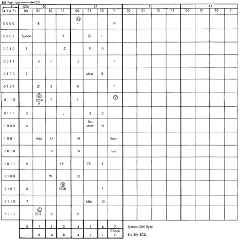
Figure 11. Code Structure for 1060 Data Communication System
©
End of Transmission (EOT) indicates the end of a transmission. This puts the XIC-XA couple into thecontrol mode.
@
End of Address (.EOA) indicates the end of ad-dress and is normally followed by text. The XA beginsthe LRC accumulation with the character which follows
the
@
character.The following characters are recognized during read commands:
®
End of Block (EOB) indicates the end of a block of text. The next received character will be the LRCcharacter, which will be checked against the LRC
char-acter accumulated in the XA. The device end, channel
end status will be set with a compare. A non-compare
20
10 11