2019 2nd International Conference on Informatics, Control and Automation (ICA 2019) ISBN: 978-1-60595-637-4
Research on Measurement Method of Brake Pad Size
Based on Machine Vision
Yu-ting LIU
1, Chao WANG
1, Ya-ning YANG
2,*, Xiang-yu XU
2and Tao ZHANG
11
College of Electromechanical Engineering, Dalian Minzu University, Dalian Liaoning 116605, China 2
College of Electromechanical & Information Engineering, Dalian Minzu University, Dalian Liaoning 116605, China
*Corresponding author
Keywords: Machine vision, Size measurement, Template matching.
Abstract. In order to solve the problem of size measurement in the production process of brake pads, a size measurement method of brake pads is proposed. Firstly, the experimental environment is set up, the camera is calibrated, and the image distortion is corrected by using the parameters obtained from the calibration. Then the brake pad image is collected and the image template is created for template matching. Finally, the distance of the target region is obtained by generating the measured rectangle. Through many tests of brake pads, the experimental results show that the method is accurate and real-time for brake pad size measurement, and provides an excellent reference for practical production measurement.
Introduction
Brake pad is one of the key parts in automobile braking system. Its performance plays a decisive role in braking effect and directly affects the safety of driving. It is one of the important standards for checking the quality of brake pads to see if the size of brake pads are up to standard. However, due to the limitation of production equipment and technology. It will lead to varying degrees of wear and tear of the brake pad contour. These wear not only affect the apparent shape and size of brake pads, but also directly affect the braking performance of brake pads. Therefore, it is particularly important to measure the size of brake pads.
The traditional measurement method is mainly manual detection [2]. The workers measure the size of brake pads according to the drawings. This method not only has low detection efficiency, but also has high false detection rate and missed detection rate. Moreover, the cost of manual detection is high, which is not suitable for large-scale industrial production. In recent years, with the continuous development of image processing technology, the size measurement method based on machine vision has gradually replaced the traditional manual measurement method. And it has been widely used in the detection of large-scale industrial production. C. Fei introduced a set of brake pad automatic detection system in reference [3], which completed the tasks of image calibration, size measurement and so on. D. Zuo has put forward a measuring method of brake disc size in reference [4]. This method utilizes morphology and gray value of brake disc, uses edge extraction and local threshold segmentation algorithm, and makes use of the feature of morphology and gray value of brake disc, and makes use of edge extraction and local threshold segmentation algorithm, and makes use of the algorithm of edge extraction and local threshold segmentation. After locating the outer edge of brake disc, finally calculating the size of brake disc, L. Hu designed a set of automatic inspection device for brake disc in document [5]. The automatic detection of brake disc size can be realized, and the dynamic detection precision can reach 0.02 mm.
real-time measurement of the method used in this paper, we have measured the dimensions of each part of the brake pad, and achieved good detection results.
Camera Calibration and Correction
Camera Calibration. In order to determine the relationship between two-dimensional image and three-dimensional objective object coordinates, it is necessary to establish the geometric model of camera imaging [6], calculate the model parameters, and the process of obtaining these parameters is called camera calibration. Camera calibration is a very key link in the application of machine vision system. The accuracy of calibration results and the stability of the algorithm directly affect the accuracy of brake size measurement.
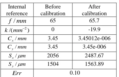
[image:2.595.197.402.348.481.2]The calibration process in this paper uses HALCON software with calibration assistant to calibrate the standard calibration board. This method has the advantages of high calibration accuracy and simple operation. Firstly, several groups of calibration plate images with different postures are collected, and the calibration plate area is separated from the image area. Then, the points on the calibration plate are segmented to extract the coordinates of the circles on the calibration plate. Finally, the camera is calibrated by the HALCON calibration assistant, and the camera calibration parameters are obtained. The calibration results are shown in Table 1.
Table 1. Calibration results.
Internal reference
Before calibration
After calibration mm
f / 65 65.7
) /(mm2
k 0 -19.9
mm
Cx/ 3.45 3.45012e-006
mm
Cy/ 3.45 3.45e-006
m
Sx/ 2056 2487.67
m
Sy/ 1504 1563.89
Err 0.10
In Table 1: f is the focal length of the camera,kis the distortion coefficient,Cxis the horizontal pixel spacing,Cyis the vertical pixel spacing,Sxis the horizontal central coordinate,Syis the vertical central coordinate, and above is the internal parameters of the camera.Erris a pixel error.
Image Correction. In the practical application, the image obtained by the camera will produce radial distortion and tangential distortion, which makes the point in the pixel coordinate system of the image change from the undistorted coordinate to the distorted coordinate. The camera imaging used in this paper mainly produces radial distortion. When correcting the distortion, the camera internal parameters obtained from single target determination are transferred to change operator as parameters to remove radial distortion, and then gen operator is used to form mapping. Finally, the image is corrected by map_ image operator, and the corrected result is obtained.
Template Matching
The method based on shape matching provided by HALCON software is mainly aimed at the small area of interest to establish the template. The specific operation flow is as follows:
(1) First determine the rectangular area of ROI, use gen_rectangle1 function to generate rectangle, and use area_center function to find the center of the rectangle.
(2) Then the ROI, of the rectangular region is obtained by using the reduce_domain function, and the create_shape_model function is used to create the rectangular template. After creating the template, we use the inspect_shape_model function to complete the monitoring template. In addition, in order to facilitate the subsequent matching, we also need to use the get_shape_model_contours function to obtain the profile of the template.
(3) After completing the above work, another image can be opened for template matching. This process is to find the image part that matches the template in the new image. This part of the work is completed by the function find_shape_model, which has many parameters, which affect the speed and accuracy of template searching.
The template matching results are shown in the Fig. 1.
a b
a b
a
b a
[image:3.595.132.465.265.362.2]b
Figure 1. Annotation results.
Measurement and Result
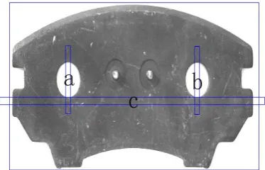
In the measurement, the coordinates of the center point of the template are obtained, and then the coordinates of the center points of the two holes in the brake pad are found. The coordinates of the center points of the circular holes are used as the coordinates of the center points of the generated rectangle at the same time, and two rectangles are generated, as shown in Fig. 2. The rectangular center point coordinate and the template center point coordinate maintain the relative position relation, thus realizes the rectangle localization function after the template matching succeeds. Then the generated rectangular parameters are assigned to the measuring rectangle, so that the measured rectangle is attached to the position of the generated rectangle, and the pixel size is measured. Finally, the measured pixel value is converted to the real length value by the operator which is converted into the world coordinate. The results of our measurements of various positions and positions of brake pads are shown in the Fig. 3.
a
b
c
[image:3.595.204.391.578.698.2]a
b
a
b a
b
[image:4.595.103.494.70.194.2]a b
Figure 3. Measurement results.
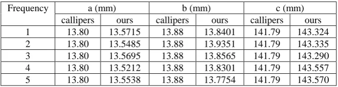
In order to test the accuracy of measurement results, we used Vernier calipers to measure the parts a, b and c of brake pads, and compared them with the methods used in this paper. We selected five groups of data to compare with each other. The comparison results are shown in Table 2.
Table 2. Comparison of results.
Frequency a (mm) b (mm) c (mm)
callipers ours callipers ours callipers ours
1 13.80 13.5715 13.88 13.8401 141.79 143.324
2 13.80 13.5485 13.88 13.9351 141.79 143.335
3 13.80 13.5695 13.88 13.8565 141.79 143.290
4 13.80 13.5212 13.88 13.8301 141.79 143.557
5 13.80 13.5538 13.88 13.7754 141.79 143.570
From the experimental results, the relative error of part a of brake pad is less than 2%, the relative error of part b of brake pad is less than 1%, and the relative error of part c of brake pad is less than 1.5%.
Conclusion
In this paper, a brake pad size measurement method based on machine learning is introduced. Compared with the traditional manual measurement method, this method can improve the measurement accuracy and efficiency more effectively. At the same time, this method can measure all the dimensions when measuring the size of brake pads, which breaks the limitation that only part of the dimensions can be measured by the general image processing method, and the measurement accuracy is significantly improved. First, camera calibration and distortion correction are carried out, and then the brake plate is located and recognized by template matching. Finally, the size of brake pad is measured. The method presented in this paper has not only theoretical value but also practical application prospect. In the future, we will apply the method proposed in this paper to the size measurement of more parts.
Acknowledgement
This work was supported by Fundamental Research Funds for the Central Universities. References
[1] X. Han, Y. Chao, Z. Zhao, H. Jin, Design of An Auto Brake Pad Thickness Detection System, J. Forestry Machinery & Woodworking Equipment, 2017, 45(07):32-36.
[image:4.595.118.464.268.357.2][4] D. Zuo, X. Chen, Size and Defect Detection System of Brake Based on HALCON, J. Electronic Science and Technology, 2016, 29(11):78-80.
[5] L. Hu, Z. Xu, X. Zhang, Y. Wang, J. Wang, Design of automatic testing devices for brake pad size, J. Journal of China Jiliang University, 2017, 28(01):45-50.
[6] Y. Liu, X. Xu, C. Wang, T. Zhang, Research on the Method of Camera Calibration System, J. Intelligent Computer and Applications, 2019, 9(3):133-137.
[7] J. Gao, T. Yang, Z. Yu, Image Template Matching Algorithm for Removing Useless Feature Points, J. Advanced Materials Research, 2011, 271-273:5.