Estimation of Frequency Dependent Attenuation of Seismic Wave in
Time-Frequency Domain
Based on Continous Wavelet Transform (CWT)
Sudarmaji1, Sismanto2, and Waluyo3
Department of Physics, Faculty of Mathematics and Natural Sciences Gadjah Mada University, Yogyakarta, Indonesia
1
[email protected], 2 [email protected] , 3 [email protected]
Abstract— Frequency dependent attenuation of seismic waves that propagate through the partially fluid saturated porous rock will be observed. The new method for estimation of frequency dependent attenuation will be developed. The frequency dependent attenuation will be calculated in time-frequency domain which obtained using a spectral decomposition method based on continuous wavelet transform (CWT). The attenuation estimation method will be applied to synthetic data of reflection seismic and vertical seismic profiling (VSP) which were obtained from numerical modeling of seismic wave propagation in partially fluid saturated porous medium using parallel processing technologies based on the Graphics Processing Unit (GPU). The synthetic data of reflection seismic and vertical seismic profiling (VSP) will be transformed to time-frequency domain using continuous wavelet transform (CWT). The frequency dependent attenuation will be calculated in time-frequency domain. The result of attenuation estimation indicates that the maximum value of attenuation is present at varying frequencies and correlated with the physical properties of the partially fluid saturated porous rock.
Keywords: continuous wavelet transform (CWT), attenuation, reflection seismic, graphics processing unit (GPU), vertical seismic profiling (VSP)
I. INTRODUCTION
Seismic method is one of the methods in the exploration and exploitation of hydrocarbons [1]. Seismic attenuation is a potential tool to discriminate pore-fluid saturation, to detect fluid mobility and to identify fluid types on the partially fluid saturated porous medium [2-10]. Calculation of seismic attenuation using spectral ratio is often inaccurate and could not be used to calculate frequency-dependent attenuation. Time-frequency analysis based on CWT (continuous wavelet transforms) could be used to model attenuation and velocity dispersion of surface wave [11,12]. This work proposes new method to calculate seismic frequency-dependent attenuation of reflection seismic and VSP (vertical seismic profiling) using time-frequency analysis based on CWT.
The effect of high fluid mobility and low fluid mobility on seismic frequency-dependent attenuation based on laboratory measurement has been done by some authors [12,13]. Seismic frequency-dependent attenuation from seismic wave passage through partially fluid saturated porous medium using numerical simulation and
laboratory measurement has been done by researchers [14-20].
II. THEORIES
A. Seismic wave propagation in fluid saturated porous medium
Propagation of elastic waves in a fluid saturated porous medium (pore-elastic) takes into account the interaction between the elastic deformation of a material and viscous fluid flow contained in the material. Biot’s theory describes the propagation of elastic waves in the partially fluid saturated porous medium and takes into account the energy dissipation of the viscous pore fluid. The theoretical model of Biot predicts attenuation and phase velocity dispersion of wave in porous elastic medium [2,3].
When the compressional seismic wave (P-wave) propagates in a fluid saturated porous rock, some parts of the rock will experience compression and dilatation. Naturally, the compressioned zone will have higher pore pressure than the dilated zone. If the pores in the rock are inter-connected, then the fluid will flow from high pore pressure to low pore pressure. This relatively fluid flow will result in a loss of energy so the wave will be attenuated [8,10].
If 𝐮 and 𝐔 describe displacement vector among the rock frame and pore fluid respectively. Displacement of pore fluid to rock frame relativley could be 𝐰which is defined as 𝐰 = 𝜙(𝐔 − 𝐮) and could be measured in volume per unit area. According to Biot (1959a) [2][3], equation of elastic wave in 2D heterogeneous isotropic porous medium and partially saturated with fluid can be written in the form of the following equations:
𝜌𝜕2𝐮 𝜕𝑡2+ 𝜌𝑓 𝜕2𝐰 𝜕𝑡2 = (𝜆𝑐+ 𝜇)∇∇ ∙ 𝐮 + 𝜇∇2𝐮 + 𝛼𝑀∇∇ ∙ 𝐰 (1) 𝜌𝑓𝜕 2𝐮 𝜕𝑡2+ 𝑚 𝜕2𝐰 𝜕𝑡2 = 𝛼𝑀∇∇ ∙ 𝐮 + 𝑀∇∇ ∙ 𝐰 − 𝑏 𝜕𝐰 𝜕𝑡 (2) where 𝜌 is bulk density in saturated medium (kg/m3), 𝜌
𝑓 is
fluid density (kg/m3), 𝑚 is massa coupling coefficient, 𝑏 is resistive damping(friction) (Pa. s/m2), 𝜇 is shear modulus 2014 International Conference on Physics (ICP 2014)
(Pa), 𝜆𝑐is Lame constant of saturated medium (Pa) , 𝛼 is
effectif Biot coefficient and 𝑀is fluid storage coefficient (Pa). While the bulk density of saturated medium (kg/m3) is defined as:
𝜌 = 𝜙𝜌𝑠+ (1 − 𝜙)𝜌𝑓 (3)
with 𝜙 is porosity (%), 𝜌𝑠 is matrix (solid) density
(kg/m3), 𝜌𝑓 is fluid density (kg/m3). The massa coupling
coefficient 𝑚 is defined as : 𝑚 =𝑇𝜌𝑓
𝜙 (4)
with 𝑇 is tortousity (no dimension). The resistive damping (friction) is defined as ;
𝑏 =𝜂
𝜅 (5)
with 𝜂 is fluid viscosity (Pa.s) and 𝜅 is fluid permeability (m2) [15,21,24,25].
B. Seismic Attenuation
Coefficient of frequency-dependent attenuation of seismic wave that propagates between two different points 𝑥1and 𝑥2(𝑥1 < 𝑥2) could be formulated as:
𝛼(𝜔) = 1
𝑥1−𝑥2ln [
𝐴(𝜔,𝑥1)
𝐴(𝜔,𝑥2)] (6)
where 𝛼(𝜔) is attenuation coefficient (dB/unit of wavelength), 𝐴(𝜔, 𝑥1) is frequency-dependent amplitude
of wave at 𝑥1 , and 𝐴(𝜔, 𝑥2) is frequency-dependent
amplitude of wave at 𝑥2 [5].
C. Continuous Wavelet Transform (CWT)
Time-Frequency Analysis of the reflection seismic and VSP (vertical seismic profiling) data can be implemented using CWT (Continuous Wavelet Transform) [17]. Continuous wavelet transform is a transformation method to analyze the frequency content of the signal automatically based on the time-scale (time-frequency) [11,12,24].
The wide scale (wide window) is used to analyze the low frequency content of the signal and the small-scale (narrow window) is used to analyze the high frequency content of the signal. Basically, continuous wavelet transform will decompose the signal which is done by convolving the signal with the wavelet. In the implementation, the wavelet will be subjected by a dilation process with dilation factor s and the translation process with translation factor u. The condition of wavelet function
)
(
)
(
t
L
2R
is its means equal zero, and could be describe as,
(
t
)
dt
0
(7) Maximum energy of the wavelet is at time t=0 and its normalization value is
(
t
)
1
. Family of waveletfunctions which are used to analyze was generated by dilating the wavelet with the scale dilatation s and translating the wavelet with translation factor u. Family of wavelet functions can be expressed as:
s
u
t
s
t
s u
,(
)
1
(8)The value of the normalization of the wavelet function family is
u,s(
t
)
1
. Continuous wavelettransformation of a function
x
(
t
)
L
2(
R
)
at time t=u and scale s is:
x
t
t
dt
s
u
W
x(
,
)
(
)
u,s(
)
(9) And its inverse is
0 2 ,(
)
)
,
(
1
)
(
s
ds
du
t
s
u
W
C
u
x
x
us (10) with
0 2)
(
~
d
C
andC
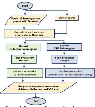
is called as admissibility conditions [24]. III. METHODOLOGY A. WorkflowSince the estimation of frequency dependent frequency will use synthetic seismogram data that generated from propagation of elastic waves in a fluid saturated porous medium, the work will start with the modeling of propagation of elastic waves in a fluid saturated porous medium [14]. The modeling is based on velocity-stress finite difference stress [26]. The modeling use first derivative of Gaussian functions as wavelet source which is injected to the stress. The modeling produces synthetic seismograms either in the form of reflection seismic or VSP (vertical seismic profiling) which depends on the used geophone configuration. Time-frequency analysis of the synthetic seismogram is done by mean continuous wavelet transforms (CWT). Estimation of frequency dependent attenuation of reflection seismic and VSP data is done in the time-frequency domain. Fig. 1 displays flowchart of this work.
Figure 1. Flowchart diagram of work
Modeling of propagation of elastic waves in a fluid saturated porous medium use parallel processing based on GPU (graphics processing unit). Fig. 2 shows the flowchart diagram of wave propagation in partially fluid saturated porous medium using GPU (graphics processing unit)
Figure 2. Workflow of wave propagation in partially fluid saturated porous medium using GPU (graphics processing unit)
GPU has been proved to accelerate the execution time compared to traditional CPU. A CPU is rarely on small number of cores, with faster execution speed
performed by each core. A GPU is rarely on vast number of cores with slower execution speed. However, if all cores capable to perform a calculation simultaneously, the usage of high number of cores will be an advantage. This concept has been known as parallel computation. This study used NVIDIA GPU with CUDA technology, which enables NVIDIA graphics card to support multi-purpose programming, beside its capability to process graphic pixel data. In order to perform multi-purpose programming using NVIDIA graphic card, an extension version of C/C++ language, known as CUDA C/C++, is used [20,27].
GPU hardware consist of a group of streaming multiprocessor (SM), each has a number of streaming processor (SP) which shares cache. Each SP consist of high number of thread, in which the computation will be executed. In this study, one grid-point of the medium is represented by one thread (Fig. 3).
Figure 3. Illustration of cores grouping in a GPU device. SM is streaming multiprocessor, and SP is streaming processor
B. Model Configuration
Model configuration of wave propagation in partially fluid saturated porous is shown in figure 4. The model dimension is 600 m x 1200 m with dx=dz=0.3m interval point. Wavelet source is deployed in point x=600m and x=30m. Row of geophones is horizontally deployed on the surface of the model with 2 m grid interval for reflection seismic configuration and vertically deployed from surface down to pass through the reservoir for VSP configuration. The reservoir is hydrocarbon reservoir containing water, oil and gas that are arranged alternately with a total thickness of 30 m at a depth of 300m from surface. Physical properties of the reservoir are described in the table 1.
There are two types of boundary condition used in this simulation: absorbing boundary condition to represent an infinite medium and free-surface condition at upper boundary of the medium, to model wave propagation in presence of surface topography (Fig. 4). For absorbing boundary, the CPML technique is used, based on [11]. PML has been proven to be efficiently absorb wave energy along the medium boundary, preventing the wave from reflecting back to the computation domain
Figure 4. Model configuration of wave propagation in partially fluid saturated porous medium Table 1. Physical properties of reservoir
IV. RESULT AND DISCUSSION
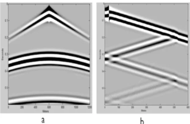
The synthetic seismogram data that was generated from propagation of elastic waves in a fluid saturated porous medium could be seen in Fig. 5. The figure shows shot gather record from reflection seismic and VSP (vertical seismic profiling). It is needed to get one or more traces from the seismic record to estimate frequency dependent attenuation.
Figure 5. Shot gather from modeling wave propagation in partially fluid saturated porous medium ; (a) Shot gather of seismic reflection , (b) Shot gather of VSP (vertical seismic profiling)
In the case of reflection seismic, the estimation of frequency-dependent attenuation is done using trace 600 and 700 (Fig. 6b and 6d). Time-frequency analysis using CWT is applied to these two traces (Fig. 6a and 6c). Direct P wave is extracted from trace 600 and assumed as source wave because its offset is zero. Maximum energy of the direct wave as function frequency could be extracted on the time-frequency domain of the trace (Fig. 6e). Reflected P wave is extracted from trace 700 for example (Fig. 6c). Maximum energy of the reflected wave as function frequency could be extracted on the time-frequency domain of the trace (Fig. 6f). The frequency-dependent attenuation of reflection seismic could be estimated using the maximum energy as a function frequency of direct wave and reflected wave (Fig. 6g). The frequency dependent attenuation from seismic wave which reflected from the medium (the partially fluid saturated porous medium or reservoir) will make Gaussian distribution with maximum attenuation is fall around 41 Hz.
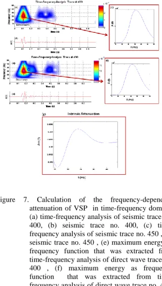
In the case of VSP (vertical seismic profiling), the estimation of frequency-dependent attenuation is done using trace 400 and 450 (Fig. 7b and 7d). Time-frequency analysis using CWT is applied to these two traces (Fig. 7a and 7c). First direct P wave is extracted from trace 400 and assumed as source wave. Maximum energy of the first direct wave as function frequency could be extracted on the time-frequency domain of the trace (Fig. 7e). Second direct P wave is extracted from trace 450 for example (Fig. 7c). Maximum energy of the second direct wave as function frequency could be extracted on the time-frequency domain of the trace (Fig. 7f). The frequency-dependent attenuation of reflection seismic could be estimated using the maximum energy as a function frequency of first direct wave and second direct wave (Fig. 7g). The frequency dependent
attenuation from seismic wave which propagates pass through the medium (the partially fluid saturated porous medium or reservoir) will make Gaussian distribution with maximum attenuation is fall around 35 Hz.
The result of estimation of frequency dependent attenuation (intrinsic attenuation) either in the form of reflection seismic or VSP (vertical seismic profiling) indicates that the maximum value of attenuation is present at varying frequencies and correlated with the physical properties of the partially fluid saturated porous medium [13, 5, 6, 8, 15, 28].
Figure 6. Calculation of the frequency-dependent attenuation of seismic reflection in time-frequency domain; (a) time-time-frequency analysis of seismic trace no. 600, (b) seismic trace no. 600, (c) time-frequency analysis of seismic trace no. 700 , (d) seismic trace no. 700 , (e) maximum energy as frequency function that was extracted from time-frequency analysis of direct wave trace no. 600, (f) maximum energy as frequency function that was extracted from time-frequency analysis of reflection wave trace no. 700, (g) frequency-dependent attenuation of seismic reflection
Figure 7. Calculation of the frequency-dependent attenuation of VSP in time-frequency domain; (a) time-frequency analysis of seismic trace no. 400, (b) seismic trace no. 400, (c) time-frequency analysis of seismic trace no. 450 , (d) seismic trace no. 450 , (e) maximum energy as frequency function that was extracted from time-frequency analysis of direct wave trace no. 400 , (f) maximum energy as frequency function that was extracted from time-frequency analysis of direct wave trace no. 450, (g) frequency-dependent attenuation of VSP
V. CONCLUSION
We have performed a series of work to calculate frequency-dependent attenuation of seismic wave using time-frequency analysis based on CWT (continuous wavelet transforms). The method has been applied to synthetics seismic data that was generated by means of parallel processing based on GPU (Graphics Processing Unit). The result of attenuation estimation indicates that the maximum value of attenuation is present at varying frequencies and correlated with the physical properties of the fluid saturated porous rock.
REFERENCES
[1] Aki, K., and Richard, P.G., 1980, A Quantitative Seismology: Theory and Methods, vol 1, W.H. Freemann, New York.
[2] Biot, M.A., 1956a, Theory of propagation of elastic waves in a fluid-saturated porous solid. I. Low-frequency range: Journal of the Acoustical Society of America, v. 28, 168-178.
[3] Biot, M.A., 1956b, Theory of propagation of elastic waves in a fluid-saturated porous solid. II. Higher frequency range: Journal of the Acoustical Society of America, v. 28, 179-191.
[4] Gerstoft, P., 2002, CABRILLO 1.0: Acoustic, Elastic, Poroelastic Finite difference Modelling, Marine Physical Laboratory, University of California at San Diego, USA.
[5] Liner, C. L., 2012, Elements Of Seismik Dispersion: A Somewhat Practical Guide To Frequency-Dependent Phenomena, Society of Exploration of Geophysicist, Tulsa, U.S.A.
[6] Maria K., Tisato, N., Janicke, R., Quintal, B., 2014, Numerical modeling and laboratory measurements of seismik attenuation in partially saturated rock, Geophysics, Vol. 79, P. L13-L20.
[7] Masson, Y.J., and Pride, S.R., 2007, Poroelastic finite difference modeling of seismik attenuation and dispersion due to mesoscopic-scale heterogeneity, Journal of Geophysical Research, Vol. 112, B03204.
[8] Masson, Y.J., 2010, Computing the Seismik Attenuation in Complex Porous Materials, Ph.D. dissertation, University of California, Berkeley.
[9] Muller, T. M., B. Gurevich, and M. Lebedev, 2010, Seismik wave attenuation and dispersion resulting from wave-induced flow in porous rocks— A review, Geophysics,75, no. 5,p. 75A147–75A164. [10] Quintal, B., Schmalholz, S.M., Podladchikov, Y.Y, and Carcione, J.M., 2007, Low-frquency anomalies of seismik-wave reflections from poroelastics layer, 10th International Congress of the Brazillian Geophysical Society, Rio de Janeiro, Brazil.
[11] Kulesh, M., Holschneider, M., Diallo, M. S., Xie, Q., Scherbaum, F., 2005, Modeling of Wave Dispersion Using Continuous Wavelet Transforms, Pure and Applied Geophysics, Pure appl. geophys. 162 (2005) 843–855.
[12] Kulesh, M., Holschneider, M., Ohrnberger,M. and Lueck, E., 2008.Modeling of wave dispersion using continuous wavelet transforms II: wavelet based frequency-velocity analysis, Pure and Applied Geophysics, Volume 165, Issue 2, pp. 255-270,.
[13] Batzle, M. and Wang, Z. (1992), Seismik properties of pore fluids. Geophysics, 57(11):1396–1408.
[14] Martin, R , Komatitsch, D., and.,Ezziani, A. , 2008, An unsplit convolutional perfectly matched layer improved at grazing incidence for seismik wave propagation in poroelastic medium, Geophysics,vol. 73, no. 4, p. t51–t61.
[15] Masson, Y.J., and Pride, S.R., 2010, Finite-difference modeling of Biot’s poroelastic equations across all frequencies, Geophysics, Vol. 75, No. 2March-April 2010; P. N33–N41.
[16] Mavko, G., Mukerji, T., and Dvorkin, J. (1998).The Rock Physics Handbook: Tools for Seismik Analysis of Porous Medium. Cambridge University Press.
[17] Nurcahya, B.,E.,dan Sudarmaji, 2007, Stratigraphic And Structural Prospects Prediction From 3d Seismik Data Using Spectral Decomposition Analysis Based On Wavelet Transform, 4th Kentingan Physics Forum, Surakarta.
[18] Rubino, J.G., and Holliger, K., 2012, Seismik attenuation and velocity dispersion in heterogeneous partially saturated porous rocks, Geophys. J. Int. vol. 188,p.1088–1102.
[19] Sams, M. S., Neep, J. P., Worthington, M. H., and King, M. S. (1997). The measurement of velocity dispersion and frequency-dependent intrinsic attenuation in sedimentary rocks. Geophysics, 62(5):1456–1464.
[20] Sanders, J. and Kandrot E., CUDA by Example: An Introduction to General Purpose Programming, USA: NVIDIA Corporation, 2010. [21] O’Brien, G. S., 2010, 3D rotated and standard staggered
finite-difference solutions to Biot’s poroelastic wave equations: Stability condition and dispersion analysis, Geophysics, Vol. 75, No. 4July-August 2010; p. T111–T119.
[22] Wenzlau, F., 2009, Poroelastic Modelling of Wavefields in Heterogeneous Medium, Ph.D. dissertation, Karlsruhe University. Karlsruhe.
[23] Wenzlau, F., and Muller, T. M., 2009, Finite-difference modeling of wave propagation and diffusion in poroelastic medium, Geophysics, Vol. 74, No. 4, P. T55–T66.
[24] Chui, C.K., 1992, ’An Introduction to Wavelet’, Academic Press, San Diego.
[25] Virieux, Jean, 1986, P-SV Wave Propagation in Hetergeneous Medium: Velocity-Stress Finite-Difference Method, International Journal of Geophysics, Vol. 51, p:610-638.
[26] Gurevich, B., Brajanovski, M., Galvin, R.J., Muller, T.M., and Toms-Stewart, J., 2009, P-wave dispersion and attenuation in fractured and porous reservoars – poroelasticity approach, Geophysical Prospecting, 57,p. 225–237.
[27] Sivalingam, K., 2010, GPU Acceleration of a Theoretical Particle Physics Application, Theses Master, The University of Edinburgh [28] Quintal, B., 2012, Frequency-dependent attenuation as a potential
indicator of oil saturation, Journal of Applied Geophysics, vol. 82,p.119–128.