A Fuzzy Logic Based Two Inductor
Boost Converter System
G.KISHOR†
Department of Electrical and Electronics Engineering, G.P.R.E.C., Kurnool, Andhra Pradesh., India‡
E-Mail: [email protected]§
D.SUBBARAYUDU
Department of Electrical and Electronics Engineering, S.I.S.T., Kurnool, Andhra Pradesh., India
S.SIVANAGARAJU
Department of Electrical Engineering, J. N. T. U., Kakinada, Andhra Pradesh.,India
E-Mail: [email protected]
Abstract:
In many power factor correction applications, the power level can reach maximum value and sometimes the input voltage also will be too high. For high power and high voltage applications the inductor volume and weight is the major concern of the conventional boost converter. In this paper the two inductor boost converter is adopted which uses smaller inductors yielding high power density. This paper deals with the simulation of Fuzzy Logic based two inductor boost converter system. Fuzzy Logic controller is designed in MATLAB environment for the closed loop control model. Simulation results of converter for closed loop control strategy with both PI and fuzzy logic control techniques are discussed and compared.
Keywords: PI Controller, Fuzzy Logic Controller, Two Inductor Boost Converter.
1. Introduction
In general, a single-inductor, single-switch boost converter topology and its variations exhibit a satisfactory performance in the majority of applications where the output voltage is greater than the input voltage. The performance of the boost converter can be improved by implementing a boost converter with multiple switches and/or multiple boost inductors [1]-[9].
Fig.1. Conventional model.
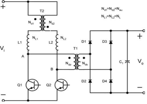
The disadvantage of conventional model two inductor boost converter leads to the development of new model with auxiliary transformer and is showed in Fig. 2. and Fig. 3. . As this model requires more space on the board, an integrated magnetic isolated two inductor boost converter is developed. This new topology is preferable than earlier models.
Fig. 2. Auxiliary Transformer model.
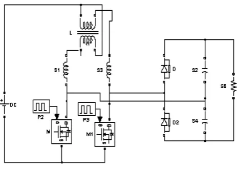
Fig. 3. Proposed model.
In recent years, the artificial intelligent (AI) techniques, such as, fuzzy controller (FC) has shown high potential for converter applications [10]. Fuzzy logic controller has the advantage that it can be designed without the exact model of the system. This approach of FC design guarantees the stable operation even if there is a change in the switching of two inductor boost converter and voltage variation.
Fuzzy logic controller for two inductor boost converter has been analyzed in detail in the literature .PI controller response has been analyzed for proposed converter control [11-13].
In this paper, fuzzy controller at different membership function is evaluated for closed loop control of two inductor boost converter. The effect of membership functions in the fuzzy control of converter is studied in Matlab/Simulink.
2. Basic Model
Fig. 4. Two Inductor Boost Converter Circuit.
Inverter output voltage is shown in Fig. 4.a. DC output voltage is shown in Fig 4.b. It can be observed that the DC output is free from ripple. The DC voltage settles at 380V. Output voltage and power increases with increase in the input voltage and power respectively.
Fig.4. a. Inverter Output Voltage.
Fig. 4. b DC Output Voltage.
3. Open Loop System
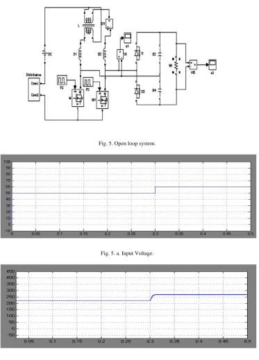
Fig. 5 shows the open loop model of Two Inductor Boost Converter Designed in MATLAB. Open loop system with step disturbance is applied at the input. Step rise in input voltage is shown in Fig 5. a. Open loop response of the output is shown in Fig 5. b. We observe the step rise in the output due to the increase in the input.
Fig. 5. Open loop system.
Fig. 5. a. Input Voltage.
Fig. 5. b. Output Voltage with disturbance
The error observed in this model can be minimized using closed loop model.
4. Closed Loop System with PI Controller
scope5
scope4 scope2 scope3
Vt2 v + -Vt 1
v +
-Scope 1 S8 S6 S5 S4 S3 S2 S11 200 S1 Pulse2 In 1 Out1 Pulse1 In 1
Out1 PI CONTROLLER
PI M1 g D S M g D S L 12 G -K-Disturbance Conn1 Conn2 DC D2 D
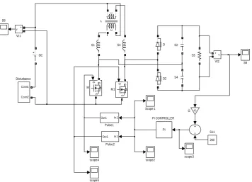
Fig. 6. Closed loop system with PI Controller.
Fig. 6.a. Input of the converter.
Fig. 6.b. Output of the converter.
The system is subjected to a step input signal of 50 V magnitude. The boost converter improves (boosted) the signal to a magnitude of 150 V. But we observe some peak overshoot in the response of the system which is undesirable.
This leads to the development of fuzzy logic controller in the closed loop system to get the desired response free from transient disturbance.
Using the functional aspects of PI controller we framed the membership functions as shown in Fig. 7. Since the controller is having one input and one output three membership functions are sufficient to design the controller.
Fig. 7. Membership functions
To maintain the voltage at desired level the trapezoidal membership of input and output are cramped near to zero for the given operating condition. For improving the controller performance, membership functions are further adjusted based on trial and error procedure. The sensitivity of a variable determines the number of fuzzy subsets, respectively. Before fuzzification, the input variables are normalized with respect to reference voltage (Vref).
This gives the system an adaptive characteristic and enables the optimal operating point to be found effectively.
The fuzzy inference includes the process of fuzzy logic operation, fuzzy rule implication and aggregation. In the fuzzy inference system, the fuzzified input variables are processed with fuzzy operators, and the IF-THEN rule implementation. The proposed system has 9 (3x3) possible rules as described in Table-1 that can build by crossing the fuzzy sets considered for each input.
The input and output membership functions are indicated with I1, I2, I3 and O1, O2 and O3 respectively. Assign the rules to the controller as per the framed membership functions. The full set of rules is summarized in the Table1 below.
Table 1. Fuzzy rule base matrix.
The value of output signal is determined in accordance with the linguistic rules. The required rules and data are supplied by the rule base. The linguistic output data is converted back into crisp output data by defuzzification.
Surface viewer which is the response of the fuzzy logic controller in Matlab environment for above constraints is shown in Fig. 8.
I/O NS Z PS
NS 1 0.5 1
Z 0.5 0 1
scope5 scope4
scope3 scope2
Discrete, Ts = 5e-005 s
pow ergui v + -Vt2 v + -Vt1 Scope1 S8 S6 S5 S4 S3 S2 200 S11 S1 In1 Out1 Pulse2 In1 Out1 Pulse1 g D S M1 g D S M 1 2 L -K-G Fuzzy Logic Controller Conn1 Conn2 Disturbance DC D2 D
Fig. 8. Surface viewer of FLC.
6. Closed Loop System With Fuzzy Logic Controller
Fig. 9 shows the closed loop model of Two Inductor Boost Converter with fuzzy logic controller designed in MATLAB. Closed loop system with Fuzzy logic controller with step disturbance is applied at the input.
Fig. 9. Closed loop system with FLC.
Step rise in input voltage is shown in Fig 9. a. closed loop response of the output is shown in Fig 9. b.
Fig. 9.a. Input of the FLC.
Fig. 9. b Output of the converter.
The closed loop system with FLC is subjected to a step input signal of 50 v magnitude. The output of the system is improved (boosted) to 150 v magnitude. This proposed model not only boosts up the voltage and also produces a signal free from transient noise. Hence the performance of the closed loop system can be improved using fuzzy logic controller.
7. Conclusion
For the two inductor boost converter system, the inductor values are significantly reduced. The two-inductor boost converter controls were studied with both PI controller and Fuzzy Logic controller. Results were analyzed and discussed using MATLAB Simulink. We observed that the output voltage of the system using FLC, is boosted and also produce a signal free from transient noise that makes reduced effect of Electromagnetic interference (EMI). Thus the utilization of smaller inductors and the fuzzy controller improves the efficiency of the proposed two inductor boost converter system.
References
[1] Y.Jang and M.M.Jovanovic, “New two-inductor boost converter with auxiliary transformer,” in Proc.IEEEAPEC’02Conf, 2002, pp. 654–660.
[2] Y.Jang and M.M.Jovanovic, “Two-Inductor Boost Converter,” U.S. Patent6239584, May29, 2001.
[3] E.Bloom, “New integrated-magnetic dc–dc power converter circuits & systems,” in Proc.IEEE APEC’87 Conf., 1987, pp.57–66. [4] R.Severns and E.Bloom, Modern DC/DC Switch mode Power Converter Circuits. New York: Van Nostrand Reinhold, Dec.1985 [5] J. Zhang, J. Shao, P. Xu, F. C. Lee, and M. M. Jovanovic´, “Evaluation of input current in the critical mode boost PFC converter for
distributed power systems,” in Proc. IEEE Appl. Power Electron. Conf. (APEC), 2001, pp. 130–136.
[6] E. X. Yang, Y. Jiang, G. Hua, and F. C. Lee, “Isolated boost circuit for power correction,” in Proc. IEEE Appl. Power Electron. Conf. (APEC), 1993, pp. 196–203.
[7] P. J.Wolfs, “A current-sourced dc-dc converter derived via duality principle from half bridge converter,” IEEE Trans. Ind. Electron., vol. 40, pp. 139–144, 1993.
[8] G. Ivensky, I. Elkin, and S. Ben-Yaakov, “An isolated dc-dc converter using two zero current switched IGBT’s in a symmetrical topology,” in Proc. IEEE Power Electron. Spec. Conf., 1994, pp. 1218–1225.
[9] W. C. P. de Aragão Filho and I. Barbi, “A comparison between two current- fed push-pull dc-dc converters—Analysis, design and experimentation,” in Proc. IEEE Int. Telecommun. Energy Conf., 1996, pp. 313–320.
[10] W. Abida, D. Sadarnac, and P. Henrard, “Minimization of conduction losses in the boost converter with galvanic isolation,” in Proc. IEEE Int.Telecommun. Energy Conf., 2001, pp. 334–340.
[11] Z. I. Kovatchev, “Design of 1.2 kW inverter building block for telecommunication supply systems,” in Proc. IEEE Int. Telecommun. EnergyConf., 2002, pp. 188–194.
[12] P. Mattavelli, L. Rossetto, G. Spiazzi, and P. Tenti, General-purpose fuzzy logic controller for dc-dc converters, IEEE Trans. Power Electronics, 12, 79–86 (1997).
[13] B. K. Bose, Expert system, fuzzy logic and neural network applications in power electronics and motion control, Proc. IEEE, 82, 1303–1323 (1994).
[14] A. Balestroni, A. Landi, and L. Sani, Cuk converter global control via fuzzy logic and scaling factors, IEEE Trans. Ind. Applic., 147, 107–112 (2000).
[15] K. Viswanathan, R. Oruganti, and D. Srinivasan, A universal fuzzy controller for a nonlinear power converter, FUZZ-IEEE’02 Conf. Rec., pp. 46–51 (2002).
[16] Yigang Shi, and P. C. Sen, A new defuzzification method for fuzzy control of power converters, IEEE, pp. 1202–1209 (2000). [17] Yigangi Shi, and P. C. Sen, Application of variable structure fuzzy logic controller for dc-dc converter, IECON’01: The 27th Annual
Conf. of the IEEE Industrial Electronic Society, pp. 2026–2031 (2001).