Electromagnetic V8 Engine Prototype
Gabriel Gonçalves Pessoa de Castro
1, Douglas Nunes dos Santos
2, Karine
Dutra Zamluti Soares
3, Larissa Pimenta
4, Thalles Lacerda Lage de
Freitas
5, Vinícius Magalhães Campos
61(Doctor in Materials Engineering Engineering / Federal Fluminense University, Av. dos Trabalhadores - Vila
Santa Cecília, Volta Redonda – RJ - Brazil - Zip Code: 27255-125)
2,3,4,5,6
(Mechanical Engineer / Resende Engineering College, Av. Cel. Prof. Antonio Esteves, 1 – Campo de
Aviação, Resende -RJ - Brazil - Zip Code: 27523-000)
Received 30 September 2019; Accepted 15 October 2019
Abstract: The plan to ban fossil-fueled cars is a goal on the world stage. Countries such as Germany, France,
the United Kingdom and the USA have expressed their intention to marketing of purely electric vehicles from 2025. Hybrid models like the Toyota Prius and Tesla vehicles have been part of everyday life in these countries for almost a decade, including in Brazil. The proposed article corresponds to the demonstration, development of an alternative for motor vehicles with the presentation of a V8 engine with electromagnetic pistons (prototype) in order to bring the concepts of sustainability and economy of models to internal combustion for the electric vehicle market.Keywords: electric vehicle, electromagnetic, fossil fuels, hybrid, v8.
I.
INTRODUCTION
The production of electric cars accelerates the world, already causes changes in the automobile industry and promises transformations in urban mobility. The global fleet of electric and hybrid cars, named for models using an electric motor in conjunction with an internal combustion engine, surpassed 2 million units in 2016, an increase of 60% over the previous year. China, Japan, the United States and Europe are the main markets and concentrate the largest manufacturers. The stock of electric cars in the world could reach 70 million units by 2025, according to the International Energy Agency (IEA) Global EV Outlook 2017 report (VASCONCELOS, 2017) [1].
The trend of electric cars is an inexorable reality. Technology and advances in Industry 4.0 have provided large corporations with the opportunity to transform the science fiction dream into a highly tangible reality. According to Tony Seba (2017) [2], all land transport will now be based on electricity and the pace of innovation in this area only tends to accelerate.
Electric motors as an alternative to reducing emissions by cars depend on how energy is made. A country like France, the investment in electric, the balance becomes positive, because there the energy base of the country is nucellar, which does not pollute the air. However, if the same decision were made by China, the world would have a problem, since practically all the energy consumed in the Asian country is thermoelectric, coming from plants that use coal - harmful to the population's airways. (WARNECKE, 2016) [3].
In Brazil, the bill, Senate Bill 304/2017, prohibits, from 2030, the commercialization and, from 2040, the circulation of new vehicles that use a combustion engine, unless they exclusively use biofuels such as ethanol. The project also allows the sale of vehicles powered by electricity.
In line with the current state of the Brazilian energy balance, this paper describes the simple presentation of a small prototype of an eight- piston electric motor that operates by magnetic induction. The project presents a low-cost solution, involving the construction of components that require some degree of technical knowledge of machining and metal forming, and involves relatively simple concepts of electromagnetism and mechanics.
II.
LITERATURE REVISION
2.1. Electromagnetic v8 engineIn this section we will present a theoretical foundation alluding to the basic concepts of electricity and mechanics regarding the application to the article objects in order to level the readers knowledge. The objective is to identify the fixed and movable components that make up the engines and their functions, comparing parts and mechanical elements of an internal combustion engine (MCI) and the V8 electromagnetic engine developed by the team, always following in this order.
2.1.1. Normal piston of an internal combustion engine
Piston is the part of the engine that receives the gas expansion movement. It is usually cylindrical in shape and made of aluminum alloys. In common pistons are two types of rings: sealing rings - located closer to the top (head) of the piston; grease rings - located on the bottom of the piston for the purpose of lubricating the cylinder walls. The piston connects to the connecting rod via a pin.
In an internal combustion engine, the piston moves in an alternate straight motion within the cylinder liner. By definition a piston can be said to be the part of a moving pump mechanism driven by a fluid or fuel explosion.
Figure 1 – Piston and conrod: Exploded views of components.
The piston of an engine is connected to the connecting rod and needs a spark from a spark plug to run. The combination of the three spark, fuel and air elements causes a controlled explosion by pushing the piston rod away, thereby generating movement. This movement will be transmitted to the crankshaft
2.1.2. Piston of an electromagnetic V8 engine
In V8-T, rods are connected to a piston. These pistons are attracted by the electromagnetic field generated in the coils as shown in figure 2. The pistons are equivalent to the femur bone of the human leg. They are responsible for exerting force while still allowing movement of the rest of the joint through the knee
Figure 2 - Piston representation of the electromagnetic motor – copyright.
2.2. Connecting rod
2.2.1. Connecting rod of an internal combustion engine
transforms the straight movement of the pistons into rotary motion of the crankshaft. In MCI the connecting rod head rotates on the pin through two-piece bearings. The metal used depends on the kind of engines, the loads of the rod and the speed of rotation (TILLMANN, 2013) [5].
Figure 3 - Connecting rod to the left: internal combustion engine connecting rod, to the right: connecting rod for electromagnetic engine – copyright.
2.2.2. Connecting rod of an electromagnetic V8 engine
For V8 Electromagnetic, the connecting rod function does not differ from the MCI. The differential is the coupling of the foot to the crankshaft, the shape of the head and the junction with the piston body.
2.3. Valves
2.3.1. Valves of an internal combustion engine
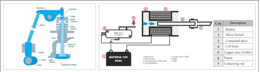
Valves are metal elements that are responsible for sealing the air inlet opening and sealing flue gas outlet holes. There are two types of valves: intake valves and exhaust valves. The first one opens to allow the fuel / air mixture (or fresh air as appropriate) to enter the cylinders. The other, exhaust, opens to exhaust the gases burned in the combustion. Engines with suspended valves have valves placed over the cylinders. This arrangement allows for a more rational form of the combustion chamber, favors engine power and superior thermal efficiency. The position of the suspended valves results in better performance at high speeds and is suitable for powerful engines with high volumetric ratio. (TILLMANN, 2013) [5].
2.3.2. Valves of an electromagnetic V8 engine
For electric motors the valves are replaced by electronic control system. In this project, as the development is simple to perform, for drive control and tripping of the coils, limit switches were used. These keys also receive the title of Micro-switch.
Figure 4 - Automatic drive system. Left: Valve position and its internal combustion engine components, right: V8 microswitch drive system - copyright.
2.4. Micro-switch - electromagnetic V8 engine
Limit switches, or microswitch, are electromechanical devices designed to indicate that a motor or structure connected to its axis (an automatic gate, for example) has reached the end of its field of motion (ANDRADE, 2017) [6].
positioned on the engine block, its shaft when cranked by the crankshaft causes an electrical pulse to be sent to the coil circuit
2.5. Crankshaft shaft
For both MCI models and electric motors, the concept and foundation of the crankshaft are the same. The crankshaft is a component element of the engine power system, also known as Crankshaft (EDM) or Crankshaft (ADM). It is considered the driving axle itself, which, in most cases, is installed in the lower part of the block, receiving also the connecting rods that give it movement. The apparent loads of a crankshaft result in tensions due to bending, twisting and shearing along its entire length. The complex geometry involved would make accurate stress calculations impossible, even if the loads were known precisely. The axle line is the set of trunnions, fixed seating points of the clamping bearings in the block, in which the crankshaft is supported by the engine block (TILLMANN, 2013) [5].
Figure 5 - Crankshaft. Left: normal crankshaft of an internal combustion engine, right: V8 electromagnetic crankshaft – copyright.
2.6. Cylinder
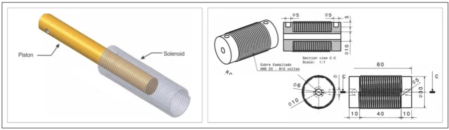
Cylinders are, in practice, the main defining factors of what a V8 engine is. They are the main structures around which the other parts of the engine are built. The cylinder is practically where all the action comes from. They are cylindrical structures coupled to the coils. In the V8-T, they are in two parallel rows of four cylinders, in diagonal position. Inside it contains every magnetic field generated by the solenoid the instant the crankshaft activates the micro switch key. It is from the electromagnetic force that the movement of the pistons begins.
2.7. Coil solenoid
A moving electric charge or electric current is known to produce a magnetic field in its vicinity. The direction of this field is along the coil axis and its direction is given by the “right hand rule” (Ampère's Law). The magnetic field generated inside the coil (solenoid) through the high intensity current pulse attracts any metallic object inside it. In the special case of V8, the inserted object is the piston. According to Carvalho, Silva e Castro (2015) [7] the currents are induced by the object (piston), and due to the effect of Lorentz forces (JxB), an acceleration occurs
2.8. Battery
The main pillar for the development of electric motors lies in the technical specification of the power supply. The success factor for these projects is the correct sizing, composition, duration, weight and power of the batteries. Contrary to what most people believe, there was not much technological innovation focused on the mechanical development of electric cars. The difference of the cars of the future lies in the technology focused on the storage and charging time of large batteries.
On composition, Husain (2003), cited by Carvalho, Silva e Castro (2015) [7], cites the lead acid battery invented by the French Gastón Planté in 1859, to have more mature technology, since it is produced since the second half of the nineteenth century, is also the most produced in the world, totaling over 100 million batteries manufactured annually. More than 60 million cars produced annually worldwide are equipped with a new lead acid battery and the life of such a battery is approximately three years.
III.
OPERATING PRINCIPLE
movement from 0 ° to 90 °. This sequence repeats for the other pistons (piston + connecting rod) so that the crankshaft rotates 360º.
The behavior of electromagnetic pistons is similar to internal combustion (MCI) engines whose piston arrangement in the cylinder is also at “V”. The difference is the fuel used for piston movement and the nomenclature given for each MCI time: intake, compression, combustion and exhaust as shown in Figure 2.
IV.
ELECTRICAL SYSTEM
The electrical system adopted for the prototype involves user-friendly on / off electronics and is further detailed in the following chapter. However, it is worth mentioning the electronic control model widely used in electric vehicles that presents a block diagram, shown in simplified form in figure 3. Described by Barreto (1986) and cited by Carvalho, Silva e Castro (2015) [7], a CC / AC electric vehicle (battery current and altered current in the motor) would have increased its performance as well as the drive ability of the driver.
V.
IDEALIZATION AND DESIGN
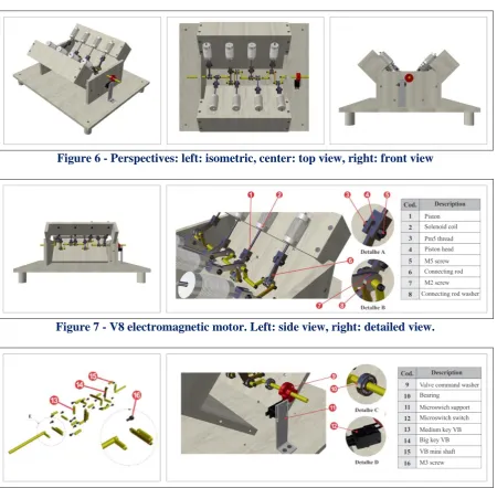
In this field we will present the project images in their detailed and complete version.
Figure 6 - Perspectives: left: isometric, center: top view, right: front view
Figure 7 - V8 electromagnetic motor. Left: side view, right: detailed view.
VI.
RESULTS
6.1. Presentation and discussion of resultsDuring the making of parts and during engine assembly, the team found some improvement opportunities. Initially, the estimated range of rotation was 178 RPM (revolutions per minute) but by increasing the outside diameter of the coil and replacing the four 90 ° washers with two 180 ° washers, the design reached 500 RPM. With these changes there was both increased motor autonomy and the economy of two microswitch.
The economy of these two spare microswitches was of paramount importance. The group found that of all parts designed or purchased, the shortest parts are the limit switches. This points to a future opportunity for innovation. The use of electrical controls, as mentioned in paragraph six of this instrument, are alternatives for improving project performance.
The team was able to make better use of the investment by using part of discarded parts when making the mechanical elements. This recycling generated savings of 65% of the estimated initial value.
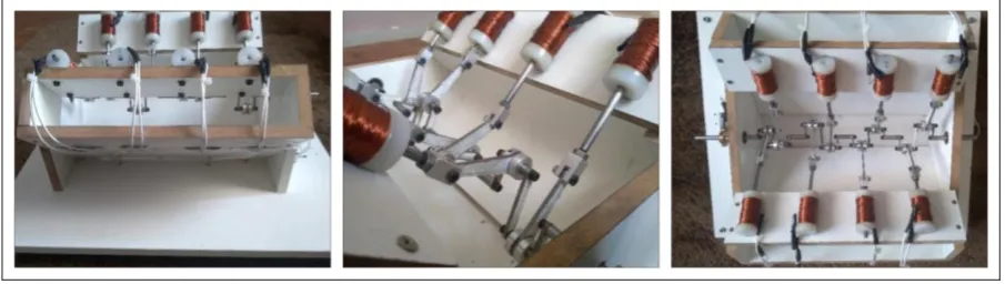
Figure 9 – Real project V8 electromagnetic motor.
Through the video available at the link <https://youtu.be/K5TIoszMODE> you can check the functionality of the project as well as proof of the scope of this article.
Datasheet:
• Title: V8 - Electromagnetic as a model for electric motors; • Year of realization: 2018;
• Direction and producer: Douglas Santos and Karine Zamluti; • Gender: educational; • Accomplishing team: project team.
Table 1 - Costs and hours table
Activity Order Stage Duration
(hours) Price US$
Project
1 Calculations 6 0.00
2 3D and 2D modeling 88 0.00
3 Banner Making 25 0.00
4 Material Selection 3 0.00
Material Acquisition 5 Acquisition 2 50.00
6 Collection of recyclables 2.5 0.00
Machining of parts 7 Parts forming 45 0.00
Motor mounting 8 Assembly 40 0.00
Report 9 Article / Report 18 0.00
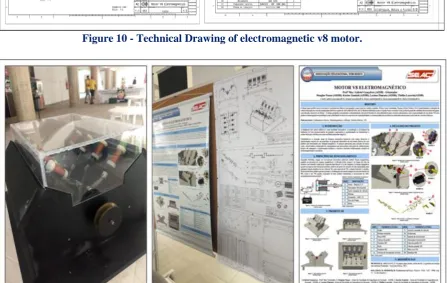
Figure 10 - Technical Drawing of electromagnetic v8 motor.
Figure 11 - Images of completed project and AEDB scientific activities week.
VII.
CONCLUSION
The time is coming that electric cars will be mostly on public roads. They promise to continue to grow due to the rise of the world's major powers in adopting electricity as a clean source for motor vehicles. The article deals with the design and analysis of a small electric motor. A prototype was conceived with constructive and operational aspects similar to the internal combustion engines in order to promote yet another electric motor modeling option and consequently corroborate for the improvement of the environment quality.
The team concludes that the present work, besides resulting in a prototype that will help students who use it in the disciplines of mechanics and electrical, allowed us to broaden the horizons of knowledge related to Industry 4.0, source of clean energy and Globalized alignment in focus on self-propelled electric vehicles
REFERENCES
[1] Y Vasconcelos, The rise of electric, Legal Environment, legislation, environment and sustainability,
2017.
International organization of Scientific Research
44 | Page
[3] W. Warnecke, Air will be future fuel source, Abesco, 2016.[4] Dd
[5] C.A.C. Tillmann, Combustion Engines Internal and its Systems (Federal Institute of Education, Science and Technology, Brazil: Pelotas-RS, 2013)
[6] C. Andrade, what is limit switch and where to use, electrical room, 2017.
[7] D.B.S. Carvalho, M.H. Silva, A.O. Castro, The New Electric Truck Motors, Mechanical engineering
course – Uninorte, 2015.