A Location-Adaptive Key Establishment Scheme
for Large-Scale Distributed Wireless Sensor
Networks
Ashok Kumar Das
Department of Computer Science and Engineering
International Institute of Information Technology, Bhubaneswar 751 013, India Email:iitkgp [email protected]
Abstract— The establishment of pairwise keys between
com-municating neighbor nodes in sensor networks is a challeng-ing problem due to the unsuitability of public-key crypto-graphic techniques for the resource-constrained platforms of sensor networks and also due to vulnerability of physical captures of sensor nodes by an adversary/enemy. In this paper, we propose a new location-adaptive key establishment scheme which is considered as an improved alternative to the path key establishment phase of bootstrapping protocol in a sensor network. Our proposed scheme offers signifi-cantly better network connectivity compared to that for the path key establishment. Moreover, our scheme has better trade-off between communication overhead, computational overhead, network connectivity and resilience against node capture attack than the path key establishment.
Index Terms— Distributed sensor networks, Location-adaptive key pre-distribution, Path key establishment, Key establishment, Security
I. INTRODUCTION
Recent advances in wireless communications and elec-tronics have enabled the development of cost, low-power, multi-functional sensor nodes that are small in size and communicate untethered in short distances. These tiny sensor nodes, which consist of sensing, data processing, and communicating components, leverage the idea of sen-sor networks. Thus, the sensen-sor networks give a significant improvement over the traditional sensors.
In a sensor network, many tiny computing nodes called sensors are scattered in an area for the purpose of sensing some data and transmitting data to nearby base stations for further processing. The transmission between the sensors is done by short range radio communications. The base station is assumed to be computationally well-equipped whereas the sensor nodes are resource-starved. The sensor nodes are usually scattered in a sensor field (i.e., deployment area or target field). Each of these scattered sensor nodes has the capabilities to collect data and route data back to the base station. Data are routed back to the base station by a multi-hop infrastructure-less architecture through sensor nodes. The base station may
This paper is based on “A Key Reshuffling Scheme for Wireless Sensor Networks,” by A. K. Das, which appeared in the Proceedings of the International Conference on Information Systems Security (ICISS 2005), Lecture Notes in Computer Science (LNCS), Volume 3803, pages 205-216, December 2005. c2005 Springer-Verlag.
communicate with the task manager node via Internet or Satellite. A survey on sensor networks could be found in [1], [2].
Key establishment protocols are used to set up the shared secrets, but the problem is too much complicated by the sensor nodes’ limited computational capabilities, battery energy, and available memory. As a result, asym-metric cryptography such as RSA [15] or Diffie-Hellman key exchange protocol [6] or Elliptic Curve cryptography (ECC) [17] or ElGamal cryptosystem [9] is unsuitable for most sensor architectures due to high energy consumption and increase code storage requirements. Hence, a symmet-ric cipher such as DES/IDEA/RC5/AES [14], [16], [17] is the viable option for encryption or decryption of data for secret communication in sensor network.
Pairwise key establishment between neighboring sensor nodes in a sensor network is done by using a protocol which is popularly known as the bootstrapping protocol. A bootstrapping protocol usually involves several steps. In key pre-distribution procedure, each sensor node is initialized by a set of pre-distributed keys in its memory called the key ring. This is done before deployment of the sensor nodes in a target field. After deployment, a direct key establishment (also called the shared key discovery) procedure is performed by sensor nodes in order to establish direct pairwise keys between them. Two nodes uand v are called the physical neighbors if they are within communication ranges of one another. They are called the key neighbors if they share at least one common key in their key rings. They are finally called the
direct neighbors if they are both the physical neighbors
and the key neighbors. After direct key establishment, if the nodes fail to establish direct keys between them, they perform the path key establishment phase. In this phase, a secure path is established between two neighbor nodes and a secret key is transmitted securely along that path.
the q-composite schemes, if a small number of sensors are compromised, they may reveal to a large fraction of pairwise keys shared between non-compromised sensors. However, the random pairwise keys predistribution is per-fectly secure against node captures, but there is a problem for maximum supported network size. Liu and Ning’s polynomial-pool based key predistribution scheme [13] and the matrix-based key predistribution proposed by Du et al. [8] improve security considerably. An improved alternative of path key establishment is proposed in [5]. This scheme allows to establish direct keys between non-neighbor nodes in a sensor network. The main advantage of this scheme is that it provides secure routing between two non-neighbor nodes via a multi-hop path using end-to-end encryption/decryption procedure rather than link-to-link encryption/decryption procedure. As a result, this scheme requires less computational overhead for secure routing. In this paper, we present a new location-adaptive key establishment scheme which is an improved alterna-tive to the path key establishment in order to establish pairwise keys between neighbor sensor nodes.
The rest of the paper is organized as follows. Next Section describes briefly existing related works on key pre-distribution techniques in wireless sensor networks. Section III introduces our proposed scheme. Our scheme is an improved alternative to the path key establishment of the bootstrapping protocol. Section IV presents a theoretical analysis of this scheme. In Section V, we report our simulation results. In Section VI, we compare the performances of our scheme with those for the path key establishment. Finally, we conclude the paper in Section VII.
II. RELATEDWORK
In this section, we describe briefly the existing key distribution schemes: the basic random key distribution scheme [10], the polynomial-based key pre-distribution scheme [3] and the polynomial-pool based key pre-distribution scheme [13].
A. The basic random key pre-distribution scheme
Eschenauer and Gligor in 2002 first proposed a random key pre-distribution scheme [10]. Their scheme, hence-forth referred to as the EG scheme, consists the following three phases. In the key pre-distribution phase, the (key) setup server chooses a large key poolK ofM randomly generated symmetric keys. Each key is assigned a unique identifier in the pool K. For each sensor node u to be deployed, the setup server picks a random subset Ku of sizem from the poolK, called the key ring of the node
u, and then loads this subset into its memory.
After the sensor nodes are deployed in some target field, a direct key establishment phase (also called the shared key discovery phase) is performed by each sensor node in the network. First of all, each sensor node locates its all physical neighbors within its communication range. Two physical neighbors can establish a secret key
between them if there exists at least one common key between their key rings. To establish a secret key between them, they exchange the key ids from their key rings in plaintext. If there is a common key id between their key rings, the corresponding key is taken as the secret key between them and they use this key for their future secure communication. Nodes which discover that they have a shared secret key in their key rings then verify that their neighbor actually holds the key through a challenge-response protocol. Since the random subsets for the nodes are drawn from the poolKrandomly without replacement, the same key may be used for secret communication by several pairs of neighbor nodes in the network.
The path key establishment phase is an optional stage, and if executed, adds to the connectivity of the network. Suppose two neighbor nodes, say,uandvfail to establish a secret key between them in the direct key establishment phase, but there exists a secure path. Once such a secure path is discovered, u generates a new random key k and securely transmits it along this path to the desired destination node. In this way,uand v can communicate secretly and directly usingk. However, the main problem is that the communication overhead increases significantly with the number hof hops. For this reason, in practice,
his restricted to a small value, say 2 or 3.
This scheme provides better network connectivity if the key pool size is smaller. In this scheme, when the key pool size is chosen smaller, it leads to compromise a large fraction of secure communication links in the network even if an adversary captures a small fraction of sensor nodes in the network.
B. The polynomial-based key pre-distribution scheme
The polynomial-based key pre-distribution scheme pro-posed by Blundo et al. in [3] is described as follows. In the key pre-distribution phase, an offline key setup server assigns unique identifiers to all the sensor nodes to be deployed in a target field. The setup server then gener-ates randomly a t-degree symmetric bivariate polynomial
f(x, y), defined byf(x, y) =ti,j=0 aijxiyj, where the coefficientsaij(0≤i, j ≤t)are randomly chosen from a finite fieldFq=GF(q),qis a prime that is large enough to accommodate a symmetric cryptographic key, with the property that f(x, y) =f(y, x). For each sensor node u
to be deployed, the setup server computes a polynomial sharef(u, y). We note thatf(u, y)is a t-degree univariate polynomial. The setup server finally loads the coefficients off(u, y)in the memory of the sensor node u.
In the direct key establishment phase, each sensor node
ufirst locates its physical neighbors in its communication range and broadcasts its own id to its neighbors. Let u and v be two neighbors. After receiving the id of the node v, u computes the secret key shared with v as
ku,v = f(u, v). Similarly, v computes the secret key shared withuasku,v=f(v, u). Sincef(u, v) =f(v, u), both the nodesuandv store the keyku,v for their future secret communication.
nodes can establish a secret key using the same symmetric bivariate polynomial f(x, y), and there is no communi-cation overhead during the pairwise key establishment process. The main drawback is that if more thant nodes in the network are compromised by an adversary, he/she easily reconstructs the original polynomial using the
La-grange Interpolation [11]. As a result, all the pairwise
keys shared between the non-compromised nodes will also be compromised. Thus, this scheme is
uncondition-ally secure andt-collusion resistant. Although increasing
the value of t can improve the security property of this scheme, but it is not feasible for wireless sensor networks due to the limited memory in sensors.
C. The polynomial-pool based key pre-distribution scheme
In order to improve resilience against node capture of the polynomial-based key pre-distribution scheme [3], Liu et al. proposed the polynomial-pool based key distribu-tion scheme [13]. The polynomial-pool based key pre-distribution scheme can be described as follows. LetFq =
GF(q)be a finite field with aq(either a prime or2mfor some positive integerm) just big enough to accommodate a symmetric cryptographic key. Letf(x, y)∈Fq[x, y]be at-degree symmetric bivariate polynomial i.e.,f(x, y) = f(y, x). The coefficients of the polynomial f(x, y) are chosen from the finite field Fq. A polynomial share of
f(x, y) is a univariate polynomial f(u, y) for some u ∈Fq. We have, f(u, v) =f(v, u).
Thus, if two shares f(u, y) and f(v, y) of the same polynomial f(x, y) are given to two nodes, say, u and
v, they can come up with the common valuef(u, v) ∈
Fq as a shared key between them. If (t + 1) or more shares of f(x, y) are known, one can easily reconstruct
f(x, y)uniquely using the Lagrange’s Interpolation [11]. Thus, the disclosure of up totshares does not reveal the polynomialf(x, y)to an adversary and non-compromised shared keys based onf(x, y)remains completely secure. The key setup server selects a random pool K of
s symmetric bivariate polynomials in Fq[x, y] each of degree t in x and y. Some ids u1, u2, . . ., un ∈ Fq are also generated for the sensor nodes in the network, wheren is the network size. For each sensor node uto be deployed in the network,spolynomials, say,f1(x, y),
f2(x, y),. . .,fs(x, y)are randomly selected fromKand the polynomial sharesf1(u, y),f2(u, y),. . .,fs(u, y)are loaded in the key ringKuofu. Immediately after deploy-ment, each sensoru transmits the ids of the polynomial shares residing in its key ring. Two physical neighborsu
andv having shares of some common polynomial(s) can establish a pairwise key between them.
The polynomial-pool based key distribution scheme provides significantly better resilience against node cap-ture than the other existing schemes [3], [4], [10].
III. OURPROPOSEDSCHEME
In this section, we first discuss the path key estab-lishment phase of the bootstrapping protocol. We then
introduce the main motivation behind the development of our proposed scheme. We describe our scheme and also discuss the details of the messages exchanged during the key establishment procedure of our scheme.
A. Path Key Establishment
This is an optional stage, and if executed, adds to the connectivity of the network. After direct key establish-ment, the nodesuandvwhich are physical neighbors not sharing a pairwise key, can establish a direct key between them as follows.
• Step-1: u first finds for a path u = u0, u1, u2, . . . , uh−1, uh = v such that each
(ui, ui+1) (i= 0,1,2, . . . , h−1)is a secure link. • Step-2: ugenerates a random number ku,v as the shared pairwise key between uand v and encrypts it using the shared keyku,u1 betweenuandu1, and sends it to nodeu1.
• Step-3:u1retrievesku,vby decrypting the encrypted key usingku,u1 and encrypts it using the shared key
ku1,u2 betweenu1 andu2 and sends it to u2. • Step-4: This process is continued by every
interme-diate sensor node along this path until the key ku,v reaches to the desired destination node v.
Nodesuandv useku,v as the direct pairwise key shared between them for their future secret communication.
The main issue in this phase is the path discovery problem, which specifies how to find a secure path between two sensor nodes. One approach is to discover a path between a source node and a destination node, the source node picks a set of intermediate nodes with which it has established direct keys. The source node then sends requests to its all these intermediate nodes. Now, if one of these intermediate nodes can establish a direct key with the destination node, a secure path will be discovered. Otherwise, this process may continue with the intermediate nodes forwarding the request. We thus note that the discovery of a secure path between two nodes is similar to a route discovery process used to establish a route between two nodes. Since this process involves more communication overhead to establish a pairwise key between nodes as the numberh of hops of the path increases, in practiceh= 2or3 is recommended.
B. Motivation
secret matrixAi in a key spaceSi. An unused key, sayk in the key ring of a sensor nodeumay help another node
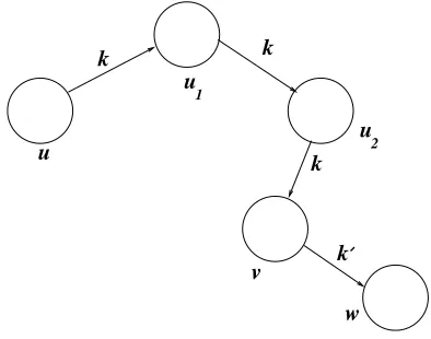
v to establish a secure link between v and its physical neighbor w with which it does not currently share a secret key. If one can discover a secure u−v path, then transmittingk securely fromuto v along this path achieves this goal. Thus, using this keyk, two neighbor sensor nodesvandwcan establish a new pairwise keyk for their future communication. This situation is depicted in Figure 1.
u
k k
k
v
w u
u
k 1
2
Figure 1. Indirect key establishment scenario between two neighbor nodesvandwwith3hops. An unused keykinu’s key ring is securely transmitted to nodev. This key helps another physical neighborw of nodevwith whichvdoes not share a key in order to establish a new secret keykbetweenvandw.
This is accomplished by the following protocol.
C. Protocol
The protocol consists of the following steps:
1) for each sensor nodeuin the sensor network: 2) for each unused keykin its key ring: 3) Transmitksecurely tou’s direct neighbors. 4) Each direct neighbor re-transmits k securely to its
direct neighbors and then deletes the keykfrom its memory.
5) Continue this process for a pre-determined number of hops.
6) Let v be a node that receives k securely during this process. Then, v broadcasts its id and the id of the key k to its physical neighbors with which it does not currently share any keys. (If sending the id of the key k is a potential threat for the network, v can ask its physical neighbors to solve some puzzle. The puzzle is encrypted with the key
k and this encrypted puzzle is sent. Thus, those physical neighbors can solve this puzzle will have the keyk.)
7) Letwbe a physical neighbor such that the id of the keykis found in its key ring.wsends a request to
v to transmit a newly pairwise key securely to be established betweenv andw.
8) v generates a random number, say k which is considered as a symmetric secret key between v
andw.vencrypts this keyk withk, and sends the encrypted key and the id of utow.
9) wretrieveskby decrypting the encrypted key using
k.
10) Nodes v and w store the key k for their future communications.
11) Nodevdeletes the unused key kfrom its memory. We note that during the key establishment procedure, all the intermediate nodes along a secure path delete the transmitted unused key. However, discovering a secure
u−v path, in particular, a long one, is costly in terms of communication overhead. For this reason, we restrict the lengths of these paths to a pre-determined threshold.
D. Protocol Messages
The above protocol is summarized below. In this nota-tion, kuv refers to the unique pairwise key shared by u andv.u→v:M refers to a messageM sent from uto
v. Ek{M} refers to a message M encrypted using key
k.M ACk(M)refers to the message authentication code (MAC) for the messageM, under the keyk. We referNu as a nonce generated by nodeu.
In order to establish a direct key between two neighbor sensor nodesvandwvia a secureu−vpath, the following messages to be exchanged:
1) To transmit an unused key kalong a secure u−v path: u = u0, u1, u2, . . . , uh+1 = v having h intermediate nodesu1, u2, . . . , uh:
ui−1 → ui : (Ekui−1,ui{ui−1, ui, k},
M ACkui−1,ui(Ekui−1,ui{ui−1, ui, k})) for
i= 1,2, . . . , h+ 1.
2) To transmit a randomly generated key k tow by
v:
v→w:Ek{w, v, u, k}, M ACk(Ek{w, v, u, k}). 3) To send a nonce tov byw:
w→v:Ek{w, v, Nw}, M ACk(Ek{w, v, Nw}). The above steps are to be carried out after the direct key establishment phase. In order to reduce communication overhead, we restrict the number of hops to 2 or3.
IV. ANALYSIS OFOURSCHEME
In this section, we derive the key connectivity of the network, i.e., the probability of establishing keys between two nodes directly or indirectly. We also analyze the security for our proposed scheme.
A. Network Connectivity
1) Network Connectivity of Our Scheme under the EG Scheme: From the analysis of [10], it follows that the
probability of two neighbor sensor nodes establishing a pairwise key is given by
p= 1−
m−1
i=0
M−m−i
M −i , (1)
node (i.e., each sensor node is capable of storingm pre-distributed keys in its key ring).
Letddenote the average number of neighbors that each sensor node can contact. Letp be the probability that an unused keykis found in a node’s key ring, andPhdenote the probability that there exist a secure u−v path, say u = u0, u1, u2, . . . , uh+1 = v having h intermediate nodesu1, u2, . . . , uh.
Derivation ofp:
We havep= 1−(probability that an unused key kis not found in a node’s key ring). The total number of ways to
selectm keys from the key pool of size M is
M m
.
For a fixed key ringKuof a nodeu, the total number of ways that keykwill not be found inKwof another node
wis
M−1 m
. Thus, we have,
p= 1−
M−1 m
M m
= m
M. (2)
Derivation ofPh:
Let us first consider h = 1. In this case, we have to compute the probabilityP1 that there exists a secure 1-hop path between nodesuandv, sayu, u1, v. Consider any one of the d neighbors of the source node u. The probability that it shares a pairwise key with both the source nodeu and the destination nodev is p2. As long as one of thednodes can act as an intermediate node, the source and the destination nodes can establish a common key. Thus, we have:
P1 = probability that a secure 1−hopu−v path exists betweenuandv
= probability that u and v establish a pairwise key (directly or indirectly)
= 1−(1−p)(1−p2)d.
We can generalize this formula for h hops. Hence, we obtain:
Ph=
1−(1−p)(1−p2)d, ifh= 1.
1−(1−Ph−1)(1−p Ph−1)d, ifh≥2. (3)
LetPindirect represent the probability that two neigh-bor sensor nodes v and w establish a pairwise key after applying our scheme for h hops. It is easy to observe from the protocol described in Section III.C that two neighbor nodes v and w can establish a pairwise key only if there exists a secure h-hop u−v path: u = u0, u1, u2, . . . , uh+1 = v having h intermediate nodes
u1, u2, . . . , uh as well as the id of an unused key k in key ringKuof nodeuexists in key ringKwof nodew. As a result, we obtain the formula for Pindirect as:
Pindirect = 1−(1−Ph)(1−p)f or h≥1. (4) For example, let us consider h = 1. Then, we have,
Pindirect = 1−(1−p)(1−P1) = 1−(1−p)(1−
p)(1−p2)d.
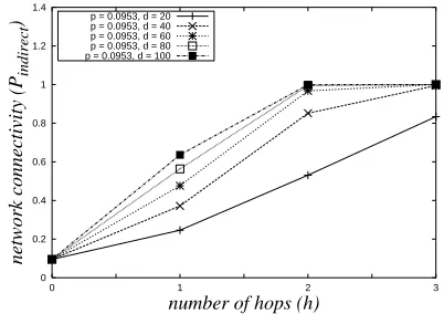
Figure 2 illustrates the probabilities,PindirectforM =
100000, m = 100 (so that p = 0.0953), and for
several values of d. This figure shows that the network connectivity increases as the average number of neighbors increases. It also tells us that even if the network is likely to remain disconnected with high probability initially, one can obtain high network connectivity after applying few hops of our scheme.
0 0.2 0.4 0.6 0.8 1 1.2 1.4
0 1 2 3
network connectivity (P
indirect
)
number of hops (h)
p = 0.0953, d = 20 p = 0.0953, d = 40 p = 0.0953, d = 60 p = 0.0953, d = 80 p = 0.0953, d = 100
Figure 2. Theoretical network connectivity of our scheme applied under the EG scheme. AssumeM = 100000, m = 100, andd =
20,40,60,80,100.
2) Network Connectivity of Our Scheme under the Polynomial-Pool Scheme: Let s be the size of the polynomial-pool and s the number of the polynomial shares given to each node’s key ring. From the analysis of [13], it follows that the probability of two neighbor sensor nodes establishing a pairwise key is
p= 1−
s−1
i=0
s−s−i
s−i . (5)
The probabilityPindirect of two neighbor sensor nodes sharing a key using our protocol can be derived anal-ogously to the derivation in Section IV.A.1. Hence, we have:
Pindirect = 1−(1−Ph)(1−p)f or h≥1, (6) where the symbolsh,Ph, andp have the same meanings as in Section IV.A.1, and
p = 1−
s−1 s
s s
= s
s. (7)
Figure 3 shows the probabilities of establishing direct keys between neighbor sensor nodes when our protocol is applied under the polynomial-pool scheme for s =
0 0.2 0.4 0.6 0.8 1 1.2 1.4
0 1 2 3
network connectivity (P
indirect
)
number of hops (h)
p = 0.0492, d = 20 p = 0.0492, d = 40 p = 0.0492, d = 60 p = 0.0492, d = 80 p = 0.0492, d = 100
Figure 3. Theoretical network connectivity of our scheme applied under the polynomial-pool scheme. Assumes = 500, s = 5, and d = 20,40,60,80,100.
B. Security Considerations
In path key establishment, two physical neighbors, say
u andv establish a direct key via a secure h-hop path: u=u0, u1, u2, . . . , uh+1=v. In this case, a linku−v
is compromised if either of its endpoint nodes u and v is compromised, or if either of the intermediate nodes
u1, u2, . . . , uh is compromised.
In our scheme, two physical neighbors, say v and w establish a direct key via a secure h-hop u−v path: u = u0, u1, u2, . . . , uh+1 = v. Thus, a link v−w is compromised if either of its endpoint nodes v and w
is compromised, or if either of the intermediate nodes
u1, u2, . . . , uhis compromised, or if the initiating nodeu is compromised.
We observe that the security of the intermediate nodes is same for both cases. As a result, for the path key establishment, the probability that any link between two nodes is compromised is the probability that either of its endpoint nodes is compromised. If some fractionf of the total number of nodes in the network is compromised, then the required probability of the link being compro-mised is 1− (probability that neither endpoint nodes are compromised)= 1−(1−f)2≈2f if f is small.
On the other hand, for our scheme, a link is compro-mised only if either of its endpoint nodes v and w is compromised, or the initiating node u is compromised. Thus, if some fraction f of the total number of nodes in the network is compromised, then the fraction of total links compromised will be about 1− (probability that neither endpoint nodesvandw are compromised nor the initiating nodeuis compromised)= 1−(1−f)3≈3f if f is small. We note that the security against node capture of our scheme compares favorably with that for the path key establishment for the ideal case.
V. SIMULATIONRESULTS
In this section, we discuss the simulation results of the network connectivity of our scheme under both the EG scheme and the polynomial-pool based scheme. We also compare the simulation results of network connectivity of our scheme with the path key establishment under both the EG scheme and the polynomial-pool based scheme.
Figure 4. Arbitrary deployment model-I
Figure 5. Arbitrary deployment model-II
The networks are simulated on several arbitrary de-ployment fields. Our simulation suggests that the results of network connectivity of our scheme are not much sensitive with respect to different arbitrary deployment models. We have considered two deployment models which are shown in Figures 4 and 5 for simulation of our scheme. Each dot in the figures represents the deployment location of a sensor node.
For the EG scheme, we have considered the following parameter values:
• The number of nodes in the network is n= 10000. • The size of the key pool (in terms of keys) is M =
100000.
• The size of the key ring of each sensor node ism=
100.
• The average number of sensor nodes of each node isd= 100.
• The communication range of each sensor node is
ρ= 30meters.
• The areaAof the deployment field is chosen so that the maximum network size becomesn= A×πρ(d+1)2 . The theoretical as well as simulated network connectivity probabilities for our scheme under the EG scheme are shown in Figure 6. This figures clearly illustrates that the theoretical results closely tally with the simulation results under the EG scheme.
0 0.2 0.4 0.6 0.8 1 1.2
0 1 2 3
network connectivity ( P
indirect
)
number of hops (h)
Analysis (p = 0.0953, d = 100) Simulation (p = 0.0950, d = 100)
Figure 6. Network connectivity of our scheme under the EG scheme, withn= 10000, d= 100, M= 100000, m= 100.
• The number of nodes in the network is n= 10000. • The size of the polynomial pool (in terms oft-degree
symmetric bivariate polynomials) iss= 500. • The number of polynomial shares given to each
sensor node is s= 5.
• The average number of sensor nodes of each node isd= 100.
• The communication range of each sensor node is
ρ= 30meters.
• The areaAof the deployment field is chosen so that the maximum network size becomesn= A×πρ(d2+1). The theoretical as well as simulated network connectivity probabilities of our scheme under the polynomial-pool scheme are plotted in Figure 7. It also shows that both the results are closed.
0 0.2 0.4 0.6 0.8 1 1.2
0 1 2 3
network connectivity ( P
indirect
)
number of hops (h)
Analysis (p = 0.0492, d = 100) Simulation (p = 0.0485, d = 100)
Figure 7. Network connectivity of our scheme under the polynomial-pool scheme, withn= 10000, d= 100, s= 500, s= 5.
VI. PERFORMANCE COMPARISON OF OUR SCHEME WITH THE PATH KEY ESTABLISHMENT
In this section, we compare the performances of our scheme under the EG scheme as well as the polynomial-pool scheme with those of the path key establishment.
A. Computational overhead
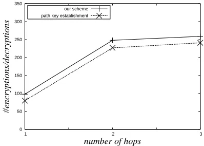
We have simulated the computational overhead re-quired by each node for our scheme and the path key establishment phase forh-hop(h= 1,2,3). The compu-tational overhead is measured by the average number of
encryptions and decryptions carried out by each sensor node during each hop.
0 50 100 150 200 250 300 350
1 2 3
#encryptions/decryptions
number of hops
our scheme path key establishment
Figure 8. Comparison of computational overhead between our scheme and the path key establishment under the EG scheme. Assume n =
10000, d= 100, m= 100, andM= 100000.
0 50 100 150 200 250 300 350
1 2 3
#encryptions/decryptions
number of hops
our scheme path key establishment
Figure 9. Comparison of computational overhead between our scheme and the path key establishment under the polynomial-pool based scheme. Assumen= 10000, d= 100, s= 5, ands= 500.
Figure 8 shows the comparison of computational over-head per each node between our scheme and the path key establishment under the EG scheme. In this figure, we have considered the initial network connectivity during the direct key establishment phase as p = 0.0953, with
m= 100 andM = 100000.
The comparison of computational overhead per each node between our scheme and the path key establishment under the polynomial-pool based scheme is illustrated in Figure 9, considering the initial network connectivity during the direct key establishment phase asp= 0.0492, withs= 5 ands= 500.
From these figures, we note that our scheme requires some more computational overhead compared to that for the path key establishment phase. However, it is justified by considering better trade-off among network connectiv-ity, resilience against node capture, communication and computational overheads compared to those for the path key establishment phase.
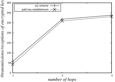
B. Communication overhead
the number of hops. On the other hand, our scheme also incurs an overhead proportional to the square of the number of hops for establishing a secure path between two nodesuandv plus the communication overhead due to establishment of a new pairwise key between neighbor nodesv andw.
0 50 100 150 200 250 300 350 400
1 2 3
#transmissions/receptions of encrypted keys
number of hops
our scheme path key establishment
Figure 10. Comparison of communication overhead between our scheme and the path key establishment under the EG scheme. Assume n= 10000, d= 100, m= 100, andM= 100000.
0 50 100 150 200 250 300 350
1 2 3
#transmissions/receptions of encrypted keys
number of hops
our scheme path key establishment
Figure 11. Comparison of communication overhead between our scheme and the path key establishment under the polynomial-pool based scheme. Assumen= 10000, d= 100, s= 5, ands= 500.
For simulation of communication overhead, we have measured the communication overhead by the average number of transmissions and receptions of encrypted keys by each sensor node during each hop of our scheme and path key establishment. Figures 10 and 11 show the comparison of communication overhead per each node between our scheme and the path key establishment under the EG scheme and the polynomial-pool based scheme respectively.
C. Network connectivity
We have compared network connectivity of our scheme with the path key establishment under both the EG scheme as well as the polynomial-pool scheme. The simulation results of network connectivity are illustrated in Figures 12 and 13. From these figures, we observe that our scheme improves the network connectivity than the path key establishment under both the EG scheme and the polynomial-pool scheme.
From the theoretical and simulation results we conclude that our scheme yields significantly better connectivity than the path key establishment under both the EG scheme as well as the polynomial-pool scheme.
0 0.2 0.4 0.6 0.8 1 1.2
0 1 2 3
network connectivity
number of hops (h)
Our Scheme (M=100000, m=100, d=100) Path Key Establishment (M=100000, m=100, d=100)
Figure 12. Comparison of network connectivity between our scheme and path key establishment under the EG scheme. Assume n =
10000, d= 100, M= 100000, andm= 100.
0 0.2 0.4 0.6 0.8 1 1.2
0 1 2 3
network connectivity
number of hops (h)
Our Scheme (s=500, 5 shares, d = 100) Path Key Establishment (s=500, 5 shares, d = 100)
Figure 13. Comparison of network connectivity between our scheme and path key establishment under the polynomial-pool scheme. Assume n= 10000, d= 100, s= 500, ands= 5.
D. Resilience against node capture
From the analysis, we observe that the security of our scheme compares favorably with that of the path key establishment for ideal situation if the fraction of the total number of nodes compromised is small. However, it is known that the resilience of the network increases dramatically with the pool size. But, bigger pool sizes lead to lower connectivity. Our scheme addresses this issue as follows. We first start with the parameter values leading to high resilience but poor initial connectivity. Then our scheme subsequently adds to the connectivity by using a few number of hops.
short time period of the direct key establishment phase of the bootstrapping, the sensor nodes can be protected fairly well during this phase; otherwise an adversary could easily compromise all the sensor nodes in a network and then take over the network. In fact, our scheme is also based on this assumption. So, our scheme provides better resilience against node compromise than that for the path key establishment as our scheme ensures better connectivity than the path key establishment.
VII. CONCLUSION
In this paper, we have proposed an improved alternative to the path key establishment phase of the bootstrapping protocol in a sensor network. Our scheme has better trade-off between the communication overhead, the computa-tional overhead, the network connectivity and also the resilience against node compromise than the path key establishment under both the EG scheme as well as the polynomial-pool scheme. Better connectivity lets one start with bigger networks and/or bigger key pool sizes, both leading to better security against node capture. Hence, our proposed scheme would be a more attractive choice than the path key establishment.
REFERENCES
[1] I. F. Akyildiz, W. Su, Y. Sankarasubramaniam, and E. Cayirci. A survey on sensor networks. IEEE
Com-munications Magazine, 40(8):102–114, August 2002.
[2] I. F. Akyildiz, W. Su, Y. Sankarasubramaniam, and E. Cayirci. Wireless sensor networks : A survey. Computer
Networks, 38(4):393–422, 2002.
[3] C. Blundo, A. D. Santis, A. Herzberg, S. Kutten, U. Vac-caro, and M. Yung. Perfectly-secure key distribution for dynamic conferences. In Advances in Cryptology
-CRYPTO’92, LNCS 740, pages 471–486, Berlin, August
1993.
[4] H. Chan, A. Perrig, and D. Song. Random key predistribu-tion schemes for sensor networks. In IEEE Symposium on
Security and Privacy, pages 197–213, Berkeley, California,
2003.
[5] A. K. Das. A Key Reshuffling Scheme for Wireless Sensor Networks. In International Conference on Information
Systems Security (ICISS 2005), LNCS 3803, pages 205–
216, 2005.
[6] W. Diffie and M.E. Hellman. New directions in cryptogra-phy. IEEE Transactions on Information Theory, 22:644– 654, 1976.
[7] W. Du, J. Deng, Y. S. Han, S. Chen, and P. K. Varshney. A key management scheme for wireless sensor networks using deployment knowledge. In 23rd Conference of the
IEEE Communications Society (Infocom’04), Hong Kong,
China, March 21-25 2004.
[8] W. Du, J. Deng, Y. S. Han, and P. K. Varshney. A pairwise key pre-distribution scheme for wireless sensor networks. In ACM Conference on Computer and Communications
Security (CCS’03), pages 42–51, Washington DC, USA,
October 27-31 2003.
[9] T. ElGamal. A public key cryptosystem and a signature scheme based on discrete logarithms. IEEE Transactions
on Information Theory, 31:469–472, July 1985.
[10] L. Eschenauer and V. D. Gligor. A key management scheme for distributed sensor networks. In 9th ACM
Conference on Computer and Communication Security,
pages 41–47, November 2002.
[11] F. B. Hildebrand. Introduction to Numerical Analysis. New York: Dover, second edition, 1974.
[12] D. Liu and P. Ning. Improving key pre-distribution with deployment knowledge in static sensor networks. ACM
Transactions on Sensor Networks, 1(2):204–239, 2005.
[13] D. Liu, P. Ning, and R. Li. Establishing Pairwise Keys in Distributed Sensor Networks. ACM Transactions on Information and System Security, 8(1):41–77, 2005.
[14] R. L. Rivest. The RC5 Encryption Algorithm. In
Pro-ceedings of the second International Workshop on Fast Software Encryption, volume 1008, pages 86–96, 1994.
[15] R.L. Rivest, A. Shamir, and L.M. Adleman. A method for obtaining digital signatures and public-key cryptosystems.
Communications of the ACM, 21:120–126, 1978.
[16] W. Stallings. Cryptography and Network Security:
Princi-ples and Practices. Prentice Hall, 3rd edition, 2003.
[17] D. R. Stinson. Cryptography Theory and Practice. Chap-man & Hall/CRC, third edition, 2006.
[18] S. Zhu, S. Setia, and S. Jajodia. LEAP+: Efficient Security Mechanisms for Large-Scale Distributed Sensor Networks.
ACM Transactions on Sensor Networks, 2(4):500–528,
November 2006.
Ashok Kumar Das is currently working as Assistant
Profes-sor in the International Institute of Information Technology, Bhubaneswar 751 013, India. He has submitted Ph.D. Thesis in the Department of Computer Science and Engineering of the Indian Institute of Technology, Kharagpur 721 302, India, in 2008. He received the M.Tech. degree in Computer Science and Data Processing from the Indian Institute of Technology, Kharagpur, India, in 2000. He also received the M.Sc. degree in Mathematics from the Indian Institute of Technology, Kharag-pur, India, in 1998. Prior to join in Ph.D. in 2004, he worked with C-DoT (Centre for Development of Telematics), a premier telecom technology centre of Govt. of India at New Delhi, India from March 2000 to January 2004. During that period he worked there as a Research Engineer on various projects in the fields of SS7 (Signaling System No. 7) protocol stack, GSM (Global System for Mobile Communications) and GPRS (General Packet Radio Services).