30 | P a g e
DEVELOPMENT AND IMPLEMENTATION OF DATA LOGGER AND
CONTROL STRATEGY FOR AUTOMATIC GEARSHIFT CONTROL FOR
TWO-WHEELER
Ashish M. Sonawane1
Department of Automobile Engineering. Rajarambapu Institute of Technology, Sakhrale
Sanjay A. Patil3
ARAI Academy [email protected]
D. G. Thombare2
Department of Automobile Engineering. Rajarambapu Institute of Technology, Sakhrale
Kiran P. Wani4
ARAI Academy [email protected]
Abstract—Before making any change in the system requires the knowledge of the current condition of the system. Data collection system is one powerful device for information of the current state of the system. In this paper, low-cost data collection system has been prepared. The Arduino platform is used together with the hall-effect sensor, throttle position sensor, clutch position and brake position sensor mounted on the test vehicle to acquire the signals from them. The main objective is to create a data logger system for a two-wheeler which can give the signal to the vehicle controller for further purpose. This data will be used for making the actual control strategy of the vehicle which helps in shift schedule in the Automated Manual Transmission (AMT) vehicle. An experimental setup is designed to acquire the above parameters and the results are plotted. The clutch position sensor is designed separately to get the exact clutch depression. Our objective is to make a data logger system which is economical. The vehicular data is obtained by driving the vehicle in normal road conditions and with zero road gradient. This acquisition system can easily be mounted on any two-wheeler with very fewer modifications in the sensor. Shift schedule for a selected vehicle is generated using GT-SUIT software
Keywords—Data logger, Arduino, Two-wheeler, Shift schedule.
I. INTRODUCTION
Data logging systems are designed to capture the data while the system is in operation, for later analysis. Basically, data acquisition is a process of acquiring physical signals from the sensors like temperature, pressure, voltage and many more physical parameters conditioning those signals and then recording them on board. Many times, a transducer is also existed to convert the signals into the required one. This stored information is used for measurement, control and analysis. [1,2]
This paper deals with the development of data logger system for two-wheelers. Arduino Mega 2560 is used for making the data logger. With the parameters like engine speed, vehicle speed, throttle position, clutch position and brake position coming from the vehicle, they are recorded in the data logger. [3,4,5]
Shift schedule is the important part of the Automated Manual Transmission (AMT) or Automatic Transmission (AT) vehicle which decides the gear number considering parameters like engine speed, load, vehicle speed, brake position, acceleration required, clutch position and brake position. [3] In this paper, this shift schedule of the required vehicle is generated using GT-SUIT software. GT SUIT is engine, powertrain, and vehicle engineering simulation software.[6]
II. METHODOLOGY
A data logger is a system which acquires physical data from sensors, converts it into digital form and then the data is conditioned and given input to the controller. The data logger system has been developed for two-wheeler for the purpose of AMT. Bajaj Pulsar 220F is selected as the test vehicle selected for this purpose.
First, the microcontroller should be selected which is a most important parameter and responsible for restriction of the system capability i.e. the number of sensors, type of sensor and sensors data reception speed. Maximum data input speed is selected from the sensors and it is found that engine speed sensor has highest signal input speed i.e. 84 Hz, when considering the maximum engine speed 10000 rpm. A higher number of analog input sensors are present in the system. Therefore, the microcontroller must have speed mention above and have additional analog input pins. For framing the control strategy, six parameters are selected which have an effect on gear shifting. These parameters are Engine speed, vehicle speed, brake position, throttle position, clutch position and gear position. Considering above and future expansion requirement Arduino Mega 2560 is selected as a microcontroller. A 20x4 line display is used for visualization of logging data online. [2]
31 | P a g e
Fig. 1. Block diagram of the system.
III. SENSOR SELECTION
The data acquired from the sensors is stored in the data acquisition system and help to control decision in vehicle control. To collect information about the vehicle operating mode following sensors are required.
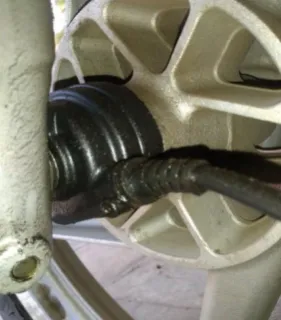
A. Vehicle Speed Sensor
It is aHall-Effect sensor having 8 poles. This sensor is mounted on the front wheel hub as shown in figure 2. This is a digital sensor which gives digital signal output, but the output signal from the sensor is weak i.e. it gives the pulses from 2 volts to 3 volts. As Arduino logic works on 5 volts the signal has to conditioned for further processing. Therefore, the input from the sensor is given to analog signal input and then it is converted to proper digital form suitable for the Arduino.
Fig. 2. Vehicle Speed Sensor
B. Throttle position Sensor:
This sensor is a disc mounted on throttle valve shaft. It is mounted below the fuel tank. It is an analog sensor which works on the principle of variable resistance.
(A)
(B)
Fig. 3. (A and B) Throttle Position Sensor.
Fig. 4. Reed switch.
C. Brake position sensor
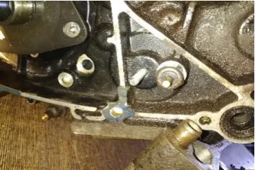
32 | P a g e D. Clutch Position Sensor
This analog sensor has made by mounting a potentiometer on the clutch shaft pin mounted on the gearbox casing as shown in figure 5.
Fisg. 5. Clutch Position Sensor.
E. Gear Position Sensor
Gear position detection is the critical part in the selected vehicle as it does not have gear position sensor or such arrangement. After exploring several options for gear position detection one solution is finalized in which it is decided to mount a potentiometer on the gearbox such that it will get the motion from gear shifter drum which is fixed position and direction. From the position of potentiometer, one can easily detect the gear position by using suitable code. [3]
(A) External view of gearbox after installing modified gear shift drum.
(B) Modified gear shifter drum.
Fig. 6. Gear Position Sensor Arrangement.
F. Engine Speed Sensor
Gasoline vehicle’s engine speed is measured by measuring number of spark in unit time. An inductive spark plug sensor followed by signal conditioning circuit can be used for measuring engine speed.
Fig. 7. Engine Speed Sensor.
A circuit is created for measuring the engine speed which works on the principle of induction. It takes the signal from the spark plug wire. High noise from the original signal is reduced in the circuit. The output signals from these sensors are given as an input to the Arduino. Developed system able to collect the data from the above sensors only. Data of engine speed and gear positioning is yet to be obtained on which work is going on.
IV. DEVELOPMENT DATA LOGGER SYSTEM AND ITS IMPLEMENTATION:
All sensors have connected to the controller and completed the data logger. The figure 8. shows the actual data logger model setup for the selected vehicle.
33 | P a g e
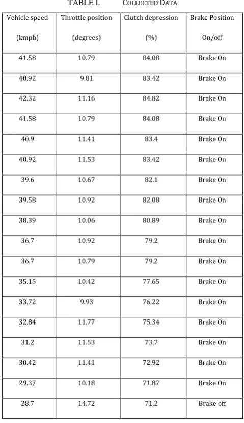
A part of data obtained from the vehicle is given below:
TABLE I. COLLECTED DATA
Vehicle speed
(kmph)
Throttle position
(degrees)
Clutch depression
(%)
Brake Position
On/off
41.58 10.79 84.08 Brake On
40.92 9.81 83.42 Brake On
42.32 11.16 84.82 Brake On
41.58 10.79 84.08 Brake On
40.9 11.41 83.4 Brake On
40.92 11.53 83.42 Brake On
39.6 10.67 82.1 Brake On
39.58 10.92 82.08 Brake On
38.39 10.06 80.89 Brake On
36.7 10.92 79.2 Brake On
36.7 10.79 79.2 Brake On
35.15 10.42 77.65 Brake On
33.72 9.93 76.22 Brake On
32.84 11.77 75.34 Brake On
31.2 11.53 73.7 Brake On
30.42 11.41 72.92 Brake On
29.37 10.18 71.87 Brake On
28.7 14.72 71.2 Brake off
The results obtained above were drawn by driving the vehicle in normal road conditions for 15-20 minutes.
V. DEVELOPMENT OF MODEL IN GTSUIT SOFTWARE.
As earlier stated shift schedule is important parameter which helps controller to take the decision of upshift or downshift considering the parameters of which data is logged. Following model is created for the given vehicle i.e. pulsar 220. [6,7,9].
Fig.9. Model in GT-SUIT software.
Fig.10. Transmission configuration.
Most of the parameter in the model has been calculated theoretically and given input to the model. Some parameters are selected from standard libraries. [8,9]
Fig.11. Engine configuration.
Shift schedule generation
34 | P a g e
upshifting of vehicle is done at higher speed when throttle position is higher. It shows the required power at that situation is higher than normal shifting time. Power required will be higher when we require high acceleration rate or vehicle is on gradient or starting load on vehicle is higher.It can be seen nearly 3-5kilometers difference in the upshift and downshift strategy in same gear thus the speed reduced while upshifting the gear is compensated with that difference. Due to that, abrupt gear shift change cannot be seen. [6,8,10,16]
Fig.12. Generated shift schedule.
VI. CONCLUSION
In this way, low-cost data collection system for the selected vehicle have been made successfully. The system can be used for data collection of several types of vehicle with slight changes in the sensors and the code. This system can be used for acquiring data from the vehicle and this data can be given as an input to the controller of the vehicle to take the essential actions.
Shift schedule is produced theoretically in the software. It gives the general ranges of speed and load of each gear to which gear shift should happen. Generated shift schedule has considered the transition period between upshift and
downshift which allows smooth gear changing without abrupt operations.
REFERENCES
[1] Abhijith B, Basil Mathew, Dolphin Dev, Vishnu S, Ms. Bibi Mohanan, “Automated Manual Transmission for Two Wheelers”, National Conference on Recent Advances in Electrical & Electronics Engineering, Vol. 5, Special Issue 3, March 2016, ISSN (Online): 2278 – 8875.
[2] Automotive Electronics for Safety, Comfort, and Reliability, Bosch Technical Instruction.
[3] G Lechner and H Naunheimer, Automotive Transmissions, Springer Publications.
[4] Jayesh Ramesh Chandiramani, Sanjam Bhandari, Hariprasad S.A., “Vehicle Data Acquisition and Telemetry” Fifth International Conference on Signals and Image Processing, Electronic ISBN: 978-0-7695-5100-5, IEEE Xplore, 2014.
[5] F. Braghin. and F. Salis., “A Low Cost System for Active Gear Shift and Clutch Control,” SAE Technical Paper. (No. 2015-01-0228). 2015. [6] C.H.F. Amendola, and M.A.L Alves, “Gear shift strategies analysis of
the automatic transmission in comparison with the double clutch transmission” SAE Technical Paper. (No. 2006-01-2872). 2006. [7] Abel, A., Schreiber, U. and Schindler, J., “Engine and gearbox
modeling and simulation for improving the shifting behavior of powertrains with manual or automated transmission”SAE Technical Paper. (No. 2006-01-1641). 2006.
[8] H. Lu, X.F.Yin, and X.H.Wu, “Shift Schedule Modification for Automated Manual Transmission Based on Road Slope Identification”. ratio, vol. 4 (1stgearratio), pp.3-41. 2015.
[9] A.V. Shinde, P. Jha, and A. Dev, “Study of optimum gear ratio selection and gear shift strategy for automated manual transmission for two wheelers” SAE Technical Paper. (No. 2015-01-1089). 2015. [10] Dolcini, P., De Wit, C.C. and Bechart, H., “Lurch avoidance strategy
and its implementation in AMT vehicles. Mechatronics,” 18(5-6), pp.289-300.2008.
[11] Surampudi, B. and Wendel, G., “Control System Development for Retrofit Automated Manual Transmissions”SAE Technical Paper (No. 2009-28-0001)..2009.
[12] Zhong, Z., Kong, G., Yu, Z., Xin, X. and Chen, X., “Shifting control of an automated mechanical transmission without using the clutch”. International Journal of Automotive Technology, 13(3), pp.487-496.2012.
[13] Prasad, M., Sardar, A. and Mubashir, S., “Transmission technologies: an Indian perspective”SAE Technical Paper (No. 2011-26-0083)..2011.
[14] Chen, H. and Gao, B., 2014. “Clutch Engagement Control of AMT Gear Shift. In Nonlinear Estimation and Control of Automotive Drivetrains”Springer, Berlin, Heidselberg. (pp. 157-178).
[15] Chen, H. and Gao, B., 2014. “Clutch Disengagement Timing Control of AMT Gear Shift. In Nonlinear Estimation and Control of Automotive Drivetrains”Springer, Berlin, Heidelberg (pp. 147-156)..