Stirling Engine
Yash Chawda Raj Aaron
UG Student UG Student
Department of Mechanical Engineering Department of Mechanical Engineering Shree L.R. Tiwari College of Engineering Shree L.R. Tiwari College of Engineering
Sudhir Gupta Shaikh Abdulwahab
UG Student UG Student
Department of Mechanical Engineering Department of Mechanical Engineering Shree L.R. Tiwari College of Engineering Shree L.R. Tiwari College of Engineering
Prof. Abhay Bendekar Assistant Professor
Department of Mechanical Engineering Shree L.R. Tiwari College of Engineering
Abstract
In order to satisfy the rising energy demands of global consumption, a new cleaner and renewable power source needs to be explored, conceptualized, and developed. Stirling engine is an engine which can be used to generate power without damage to humans or the local ecosystems and without consumption of non-renewable fuels. This project intends to improve efficiency of Stirling Engine and use of the engine for various applications without producing harmful gases and consuming fuels.
Keywords: Stirling Engine, non-renewable fuels, efficiency
________________________________________________________________________________________________________
I. INTRODUCTION
The Stirling engine is a heat engine of the external combustion piston engine type. It was invented and developed by Reverend Dr Robert Stirling in 1816.
A well-designed Stirling engine can achieve 50% to 80% of the ideal efficiency in the conversion of heat into mechanical work, limited only by friction and material properties. The engines can theoretically run on any heat source of sufficient temperature, including solar energy, chemical and nuclear fuels.
While the Stirling engine is more expensive than an internal combustion engine of the same power rating, its many unique advantages make it preferred for a variety of niche applications. Compared to internal combustion engines, Stirling engines can be made very energy efficient, quiet, reliable, long-lasting and low-maintenance. In recent years, these advantages have become increasingly significant given the general rise in energy costs and the environmental concerns of climate change. This growing interest in Stirling technology has led to the ongoing development of Stirling devices for many applications, including renewable power generation and Astronautics.
II. WORKING
Stirling engines convert any temperature differential directly to movement: they use a displacer piston to move enclosed air back and forth between cold and hot reservoirs. At the hot reservoir, the air expands and pushes a power piston, producing work and displacing the air to the cold reservoir. There the air contracts and pulls the power piston, closing the cycle.
Stirling engines can also work in reverse: when applying motion, a temperature differential appears between the reservoirs. Incidentally, one of their modern uses is in cryogenics.
III. THE ENGINE CYCLE
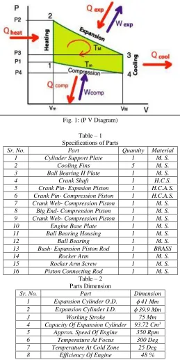
The gas follows the behavior described by the gas laws which describe how a gas's pressure, temperature and volume are related. When the gas is heated, because it is in a sealed chamber, the pressure rises and this then acts on the power piston to produce a power stroke. When the gas is cooled the pressure drops and this means that less work needs to be done by the piston to compress the gas on the return stroke, thus yielding a net power output. When one side of the piston is open to the atmosphere, the operation of the cold cycle is slightly different. As the sealed volume of working gas comes in contact with the hot side, it expands, doing work on both the piston and on the atmosphere. When the working gas contacts the cold side, the atmosphere does work on the gas and "compresses" it. Atmospheric pressure, which is greater than the cooled working gas, pushes on the piston.
To summarize, the Stirling engine uses the potential energy difference between its hot end and cold end to establish a cycle of a fixed amount of gas expanding and contracting within the engine, thus converting a temperature difference across the machine into mechanical power. The greater the temperature difference between the hot and cold sources, the greater the power produced, and thus, the lower the efficiency required for the engine to run.
Fig. 1: (P V Diagram)
Table – 1 Specifications of Parts
Sr. No. Part Quantity Material
1 Cylinder Support Plate 1 M. S.
2 Cooling Fins 5 M. S.
3 Ball Bearing H Plate 1 M. S.
4 Crank Shaft 1 H.C.S.
5 Crank Pin- Expnsion Piston 1 H.C.A.S. 6 Crank Pin- Compression Piston 1 H.C.A.S. 7 Crank Web- Compression Piston 1 M. S. 8 Big End- Compression Piston 1 M. S. 9 Crank Web- Compression Piston 1 M. S. 10 Engine Base Plate 1 M. S. 11 Ball Bearing Housing 1 M. S.
12 Ball Bearing 1 M. S.
13 Bush- Expansion Piston Rod 1 BRASS
14 Rocker Arm 1 M. S.
15 Rocker Arm Screw 1 M. S.
16 Piston Connecting Rod 1 M. S. Table – 2
Parts Dimension
Sr. No. Part Dimension
1 Expansion Cylinder O.D. 41 Mm 2 Expansion Cylinder I.D. 39.9 Mm
3 Working Stroke 75 Mm
IV. CALCULATION OF EFFICIENCY
Without Water Jacket: T1 = 573
T2 = 298
= work done / heat supplied = T1-T2/T1
= [(573-298)/573] X 100 = 47%
With Water Jacket: ( RESULT ) T1 = 573 K
T2 = 283 K
= work done / heat supplied = T1-T2/T1
= [(573-283)/573] X 100 = 52 %
V. ADVANTAGES OF STIRLING ENGINES
1) The heat is external and the burning of a fuel-air mixture can be more accurately controlled.
2) They can run directly on any available heat source, not just one produced by combustion, so they can be employed to run on heat from solar, geothermal, biological or nuclear sources.
3) A continuous combustion process can be used to supply heat, so emission of unburned fuel can be greatly reduced.
4) Most types of Stirling engines have the bearing and seals on the cool side; consequently, they require less lubricant and last significantly longer between overhauls than other reciprocating engine types.
5) The engine as a whole is much less complex than other reciprocating engine types. No valves are needed. Fuel and intake systems are very simple.
6) They operate at relatively low pressure and thus are much safer than typical steam engines. 7) Low operating pressure allows the usage of less robust cylinders and of less weight. 8) They can be built to run very quietly and without air, for use in submarines or in space.
9) They start easily and run more efficiently in cold weather, features lacking in their internal combustion cousins.
10) A Stirling engine which is pumping water can be configured so that the pumped water cools the cool side. This is, of course, most effective when pumping cold water.
11) They are extremely flexible. They can be used as CHP (Combined Heat and Power) in winters and as coolers in summers (cryocooling).
VI. DISADVANTAGES OF STIRLING ENGINES
1) Some Stirling engine designs require both input and output heat exchangers, which must contain the pressure of the working fluid, and which must resist any corrosive effects due to the heat source. These increase the cost of the engine, especially when they are designed to the high level of "effectiveness" (heat exchanger efficiency) needed for optimizing fuel economy. Fuel economy may not be an issue with the advantages of using unlimited but unusual fuel sources that a Stirling engine can make use of.
2) Stirling engines that run on small temperature differentials are quite large for the amount of power that they produce, due to the heat exchangers. Increasing the temperature differential (and pressure) allows smaller Stirling engines to produce more power.
3) Dissipation of waste heat is especially complicated because the coolant temperature is kept as low as possible to maximize thermal efficiency. This drives up the size of the radiators markedly, which can make packaging difficult. This has been one of the factors limiting the adoption of Stirling engines as automotive prime movers. (Conversely, it is convenient for domestic or business heating systems where combined heat and power (CHP) systems show promise. ref)
4) A "pure" Stirling engine cannot start instantly; it literally needs to "warm up". This is true of all external combustion engines, but the warm up time may be shorter for Stirlings than for others of this type such as steam engines. Stirling engines are best used as constant run, constant speed engines.
5) Power output of a Stirling is constant and hard to change rapidly from one level to another. Typically, changes in output are achieved by varying the displacement of the engine (often through use of a swashplate crankshaft arrangement) or by changing the mass of entrained working fluid (generally helium or hydrogen). This property is less of a drawback in hybrid electric propulsion or base load utility generation where a constant power output is actually desirable.
engine for any length of time without replacement. Typically, auxiliary systems need to be added to maintain the proper quantity of working fluid. These systems can be a gas storage bottle or a gas generator. Hydrogen can be generated either by electrolysis of water, or by the reaction of acid on metal. Hydrogen can also cause the embrittlement of metals. Helium must be supplied by bottled gas. Some engines use air as the working fluid which is less thermodynamically efficient but minimizes the problems of gas containment and supply. Most technically advanced Stirling engines like those developed for United States government labs use helium as the working gas, because it functions close to the efficiency and power density of hydrogen with fewer of the material containment issues. Hydrogen is also a very flammable gas, while helium is inert. Compressed air can also be explosive because it contains a high partial pressure of oxygen. Oxygen can be removed from air through an oxidation reaction, or equivalently, bottled nitrogen can be used.
VII.PROBLEMS WITH STIRLING ENGINES
1) Stirling engines are difficult to construct and require precise machining, thus making them both more expensive and much slower to produce.
2) Stirling engines often have much less power output than other types of engines of similar size.
3) Stirling engines, especially the type that run on small temperature differentials, are quite large for the amount of power that they produce.
4) A "pure" Stirling engine cannot start instantly; it literally needs to "warm up.”
VIII. APPLICATIONS
Combined heat and power applications:
The principal use of Stirling engines today is as an economical source of electrical power often utilising a heat source from an industrial process. WhisperGen, a New Zealand firm with offices in Christchurch, has developed an "AC Micro Combined Heat and Power" stirling cycle engine. These microCHP units are gas-fired central heating boilers which sell power back into the electricity grid. They announced in 2004 that they were producing 80,000 units for the residential market in the United Kingdom. A 20 unit trial in Germany started in 2006.
Solar Power Generation:
Placed at the focus of a parabolic mirror a Stirling engine can convert solar energy to electricity with an efficiency better than photovoltaic cells. On August 11, 2005, Southern California Edison announced an agreement to purchase solar powered Stirling engines from Stirling Energy Systems[7] over a twenty year period and in quantity (20,000 units) sufficient to generate 500 megawatts of electricity. These systems, on a 4,500 acre (19 km²) solar farm, will use mirrors to direct and concentrate sunlight onto the engines which will in turn drive generators.
Heat Pump:
A Stirling heat pump is very similar to a Stirling cryocooler, the main difference being that it usually operates at room-temperature and its principal application to date is to pump heat from the outside of a building to the inside, thus cheaply heating it.
As with any other Stirling device, heat flows from the expansion space to the compression space; however, in contrast to the Stirling engine, the expansion space is at a lower temperature than the compression space, so instead of producing work, an input of mechanical work is required by the system (in order to satisfy the second law of thermodynamics). When the mechanical work for the heat-pump is provided by a second Stirling engine, then the overall system is called a "heat-driven, heat-pump".
The expansion-side of the heat-pump is thermally coupled to the heat-source, which is often the external environment. The compression side of the Stirling device is placed in the environment to be heated, for example a building, and heat is "pumped" into it. Typically there will be thermal insulation between the two sides so there will be a temperature rise inside the insulated space. Heat-pumps are by far the most energy-efficient types of heating systems. Stirling heat-pumps also often have a higher coefficient of performance than conventional heat-pumps. To date, these systems have seen limited commercial use; however, use is expected to increase along with market demand for energy conservation, and adoption will likely be accelerated by technological refinements.
Nuclear power:
There is a potential for nuclear-powered Stirling engines in electric power generation plants. Replacing the steam turbines of nuclear power plants with Stirling engines might simplify the plant,yield greater efficiency, and reduce the radioactive by-products. A number of breeder reactor designs use liquid sodium as coolant. If the heat is to be employed in a steam plant, a water/sodium heat exchanger is required, which raises some concern as sodium reacts violently with water. A Stirling engine obviates the need for water anywhere in the cycle.
Geothermal Energy
Some believe that the ability of the Stirling engine to convert geothermal energy to electricity and then to hydrogen may well hold the key to replacement of fossil fuels in a future hydrogen economy.
REFERENCES
[1] Denisse Aranda ,stephen Wood. Stirling engine for remote power and disaster relief.(Florida International University), April 5, 2010. EML 4905.
[2] Ivan C. Oelrich, Frederick R. Riddell. Evaluation of Potential Military Applications of Stirling Engines. Institute for Defence Analysis. July 1988. MDA
903 84 C 0031.
[3] Dinesh.K, Gowtham Raj.R, Naresh.M, Rakesh.N. Design And Fabrication Of Low Cost Stirling Engine For Low Duty Industrial Applications.
INTERNATIONAL JOURNAL OF SCIENTIFIC & TECHNOLOGY RESEARCH,2014 ISSN 2277-8616
[4] Obernberger, H. Carlsen, F. Biedermann. State-of-art and future developments regarding Small-Scale biomass CHP systems and Stirling Engine
Technologies. Proceedings to the International Nordic Bioenergy conference, 2003.
[5] Hawley, J.G., Reader, G.T. A knowledge based aid for the stirling underwater vehicle (AUV) energy systems. Autonomous Underwater Vehicle
Technology, 1992.
[6] Yingxiao Yu; Zhaocheng Yuan; Jiayi Ma; Shiyu Li. Design and simulation of exhaust gas waste heat recovery system of gasoline engine based on Stirling
cycle. International Conference on Renewable Energy and Environment (ICMREE), ngdu, IEEE. 3 855-859.
[7] Ivan C. Oelrich, Frederick R. Riddell. Evaluation of Potential Military Applications of Stirling Engines. Institute for Defence Analysis. July 1988. MDA
903 84 C 0031.
[8] The Energy Hub – A Powerful stirling engine Concept for Future Energy Systems. Third Annual Carnegie Mellon Conference on the Electricity Industry,
13-14 March 2007.