© 2017 IJSRST | Volume 3 | Issue 6 | Print ISSN: 2395-6011 | Online ISSN: 2395-602X Themed Section: Science and Technology
A Study on Flexural Behaviour of Concrete Filled Steel Tubes
S. Aravind
1, D. Mohammed Rafi
2*1M.Tech Student, St.Mark Educational Institutions Society Group of Institutions, Anantapur, Andhra Pradesh, India 2
Assistant Professor, Department of Civil Engineering, St.Mark Educational Institutions Society Group of Institutions, Anantapur, AndhraPradesh, India
ABSTRACT
Concrete filled steel tubes (CFST) member have many advantages compared with the ordinary structural member made of steel or reinforced concrete. One of the main advantages is the interaction between the steel tube and concrete. Concrete delays the steel tube‟s local buckling, whereas the steel tube confines the concrete and thereby increases the concrete‟s strength. CFSTs are economical and permit rapid construction because the steel tube serves as formwork and reinforcement to the concrete fill, negating the need for either. The deformation capacity of the system is increased by the combined action of the concrete fill with the thin, ductile steel tube. The concrete fill significantly increases inelastic deformation capacity and the compressive stiffness and load capacity of the CFST member. In this work totally 9 specimens were tested out of which 3 specimens were empty steel tubes and remaining 6 specimens were concrete filled with different bonding techniques. As it is prefabricated time consumption will be less in construction practice and due to confinement more ductility is expected which is very useful in earthquake resistant structures. Load carrying capacity of CFST almost doubled in comparison with empty steel tubes. Ultimate load carrying capacity of concrete filled steel tube beams almost doubled compared to empty steel tubes. Compared to empty steel tubes, strength increase of 67.19%, 97.48% and 114.84% was observed in normal CFST, CFST with sand blasting and CFST with diagonal shear connector beams respectively. Average ultimate load of EST was 105.66kN whereas average load of CFSTB, CFSTBWSB and CFSTBWDSC was 176.66, 208.66 and 227kN respectively. The maximum load was taken by the specimen CFSTBWDSC – 03 which was 231kN, it may be because of presence of diagonal shear connector inside the tube.
Keywords: Ductility, Diagonal Shear, Steel Tubes, Confinement.
I.
INTRODUCTION
Building construction has been carried out from ancient times. Construction of building turned out to be a need due to the various climatic variations. Shelters were one means by which humans could adapt themselves to a variation in weather conditions. Earlier human shelters were very simple and it lasted just for few days or months. As time passed, they started building temporary structures which were evolved into refined forms as igloo. Gradually durability of structures began to improve, particularly after the beginning of agriculture, when people stayed in one place for longer duration of time. Structures slowly started having symbolic value and functional value, when people began to notice the difference between architecture and structural aspects. The history of buildings has been improving day by day.
One is by increasing the durability of the materials used. Initially materials used in building were perishable, like leaves, branches, and animal skin. Later, materials which had additional durability like clay, stones, timber (wood), and other synthetic materials, like brick, concrete, metals, and plastics were used.
II.
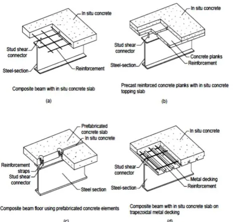
COMPOSITE CONSTRUCTION
within the resulting structural member. Research into composite steel/concrete construction began in Canada in the 1920s.
Figure 1. Different forms of composite beam and slabs
III. AIM AND OBJECTIVE
Aim: To study the flexural behaviour of concrete filled steel tube beams.
Objective:
1. To check the flexural capacity of empty steel tubes (EST).
2. To check the flexural capacity of concrete filled steel tube beams (CFSTB).
3. To check the flexural capacity of concrete filled steel tube beams with sand blasting (CFSTBWSB).
4. To check the flexural capacity of concrete filled steel tube beams with diagonal shear connectors (CFSTBWDSC).
5. To study the load deflection characteristics of EST and CFST beams.
6. To compare the load carrying capacity of EST and CFST beams.
7. Preparing analytical model using finite element based software and comparing the experimental results with analysis.
IV. METHODOLOGY
Total 12 specimens will be tested under two point loading with 100 mm support on either side of the beam:
1. 3 hollow rectangular steel tube specimen of 60x120x1000 mm of thickness 3.2 mm is tested under two point loading.
2. 3 rectangular steel tube of 60x120x1000 mm of thickness 3.2 mm is filled with nominal grade concrete without sand blasting is tested under two point loading.
3. 3 rectangular 60x120x1000 steel tube of 60x120x1000 mm of thickness 3.2 mm is filled with nominal grade concrete with sand blasting is tested under two point loading.
4. 3 rectangular steel tube of mm of thickness 3.2 mm with 10mm dia bar welded along 2 diagonals of the tube and is filled with nominal grade concrete is tested under two point loading.
5. Dial gauges will be used to find the deflection of all specimens.
6. Comparison and discussion of test results. 7. Conclusions drawn from this investigation.
V.
CONCRETE FILLED STEEL TUBES (CFST)Concrete Filled Steel Tubes (CFSTs) are composite members consisting of steel tubes and concrete infilling in it, they work compositely to carry load and offer stiffness. Boundary stresses between these two materials are required to build up this composite action. Concrete-filled steel tubes have worldwide application including columns, platforms which support offshore structures, storage tank roofs, piers of bridges, and piles. Due to their good and stable engineering properties they are used in both seismic zones and non-seismic zones. Application of the Concrete Filled Steel Tube (CFST) concept can lead to largely savings of steel when compared to the conventional structural steel systems.
Flexural behaviour of CFST:
We first need to understand how the composite concrete filled steel tube members behave under flexural loading for its effective design.
Due to the filler concrete, there is increase in moment carrying capacity in the member and thereby there is increase in energy absorption capacity of the CSFT.
VI. EXPERIMENTAL WORK
Brief procedure of experimental work carried out for this thesis work is explained in this part.
Specimens:
This experimental work was conducted to check the flexural behaviour of empty steel tube and concrete filled steel tube beams. Main objective was to find out the ultimate flexural strengths of empty and concrete filled steel tube beams. All specimens were of uniform cross section 120mmx60mm of thickness 3.2mm and of length 1000mm. Steel tubes were confirming to Indian Standard code IS 4923 : 1997. All specimens were tested under two point loading with simple supports in Universal Testing Machine (UTM) of capacity 60 tonnes.
Casting of Specimens
Empty steel tubes were available in 06 metre length. Each length was cut into 6 pieces of 1 metre length.
Fig: Empty steel tubes
Sand-Blasting of Specimens
For 3 numbers of specimens, inner surface of tubes were roughened to develop the bond between steel and concrete with epoxy resin araldite and manufactured sand (M-sand) particles of grain size retaining on 3.35mm sieve.
First inner surface was cleaned for dust and corrosion particles then a layer of Araldite was applied on inner
surface and then M-sand particles were sprinkled on that surface. Then the steel tube was left for 24 hours undisturbed.
Fig: Application of epoxy and M- sand particles
Fig: Sand blasted specimens
Welding of Shear Connectors
Fig: Shear connector welded specimens
VII.
TEST SETUP
All specimens were tested under two point static loading as simply supported condition with a span of 800mm. All specimens were tested in Universal Testing machine (UTM) of capacity 60tonnes. Dial gauge was used to measure the deflection at mid span of the beam. The load was introduced at the rate of 2.5kN/minute. Deflections were noted down at every 2.5kN interval. Load was applied up to a point when the needle comes back and final load was noted down as ultimate load of the beam and at that load, final reading of dial gauge was noted down before releasing the load.
VIII.
COMPARISON OF ULTIMATE LOAD VS.
ULTIMATE DEFLECTION OF ALL SPECIMENS
To know the behaviour of each specimen, combined ultimate load vs. ultimate deflection is presented graphically for each type of specimen.
Empty Steel Tubes (EST)
Failure pattern of all specimens in this set is same. EST – 02 took maximum load.
Fig: Load vs. Deflection curve for EST – 01, 02, 03
Concrete filled Steel Tubes (CFSTB)
Failure pattern of all specimens in this set is same. CFSTB – 03 took maximum load.
Fig: Load vs. Deflection curve for CFSTB – 01, 02, 03
Concrete filled Steel Tubes with Sand Blasting (CFSTBWSB)
Failure pattern of all specimens in this set is same. CFSTBWSB – 03 took maximum load.
Fig: Load vs. Deflection curve for CFSTBWSB – 01, 02, 03
0 20 40 60 80 100 120 140
-10 0 10 20 30
LO
A
D
IN
kN
DEFLECTION IN mm
EST-01
EST-02
EST-03
0 50 100 150 200
-10 0 10 20
LO
A
D
IN
kN
DEFLECTION IN mm
CFSTB-01
CSFTB-02
CFSTB-03
0 50 100 150 200 250
0 10 20
LO
A
D
IN
kN
DEFLECTION IN mm
CFSTBWSB-01
CFSTBWSB-02
Concrete filled Steel Tube Beams with Diagonal Shear Connectors (CFSTBWDSC)
Failure pattern of all specimens in this set is same. CFSTBWDSC– 03 took maximum load.
Fig: Load vs. Deflection curve for CFSTBWDSC – 01, 02, 03
Load Vs. Deflection For all Type Of Specimens
To know the behaviour of all specimens together, a graph is plotted considering one specimen from each type. Considered specimen has achieved maximum load in that type. EST – 02, CFSTB – 03, CFSTBWSB – 03 and CFSTBWDSC – 03 achieved maximum load in each type respectively.
Fig: Load vs. Deflection curve for each type of specimen
IX. CONCLUSIONS AND FUTURE WORK
This study was conducted to know the flexural behaviour of empty steel tubes and concrete filled steel tubes with different bonding techniques. Totally 12 specimens were used. Cross section of steel tubes, thickness of steel tubes and grade of infill concrete used
were kept constant so that the flexural behaviour of these tubes can be investigated thoroughly. An analytical model was also prepared using experimental results to know the comparison between experimental and analytical results keeping in mind that, further analytical results can be extended to full scale models. As concrete filled steel tubes are still not used as beams in structures, an attempt has been made to know the behaviour of these tubes to use as beams in construction industry.
Conclusions:
1. All the specimens failed almost in same pattern. Local buckling of steel tubes occurred at the compression zone and at point load.
2. Flexural load carrying capacity of concrete filled steel tubes doubled when compared to empty steel tubes.
3. Much difference between different bonding techniques was not seen in any of the specimen. 4. Almost all type of filled specimens failed at same load, but the maximum load was taken by the specimen CFSTBWDSC – 03, it may be because of presence of diagonal shear connector inside the tube.
5. There was no slip of concrete at the edges of beams observed in any specimen. This shows that the bond between steel and concrete is good enough.
6. The filled specimens are opened to check the behavior, failure and crack pattern of in filled concrete. Very minute cracks were developed in flexure zone and crack spacing was also more. 7. It can be concluded that the smaller cross
section of concrete filled steel tubes can carry much more load than normal reinforced concrete beams within the allowable crack width.
8. As concrete is confined by steel tube all around, sudden failure of beams may not occur.
9. Overall performance of concrete filled steel tubes are good and can be concluded that filling of concrete to empty steel tubes increases the load carrying capacity to maximum extent.
Scope for further Studies
1. Flexural behavior should be checked by changing the cross sectional dimension and thickness of the tubes.
0 50 100 150 200 250
-10 0 10 20
LO
A
D
IN
kN
DEFLECTION IN MM
CFSTBWDSC-01 CFSTBWDSC-02 CFSTBWDSC-03 0 50 100 150 200 250
-10 0 10 20
LO
A
D
IN
kN
DEFLECTION IN mm
EST-02
CFSTB-03
CFSTBWSB-03
2. Here static loading condition has been carried out, further it should be checked for dynamic loading condition also.
3. Full scale models should be analyzed to know the exact behavior of load and deflection. 4. Beam column connections with bolting and
welding should be analysed.
5. Behavior of these beams should be analyzed in conjunction with columns, preferably as concrete filled steel tube frames.
6. Fire and corrosion resistance analysis should be done with loads.
X.
REFERENCES
[1].
Dr. Andrew Wheeler, Prof. Russell Bridge,“Flexure Behaviour of Conrete-Filled
Thin-Walled Steel Tubes with Longitudinal
Reinforcement”, School of Engineering;
University of Western Sydney Locked Bag (2003), 99-130.
[2].
Arivalagan and Kandasamy, “Energy AbsorptionCapacity of Composite Beams, Journal of
Engineering Science and Technology Review”, 2 (1), (2009), 145-150.
[3].
Wie-Min Gho, Dalin Liu, “Flexural Behaviour of High-Strength Rectangular Concrete-Filled SteelHollow Sections”, Journal of Constructional Steel
Research, 60, (2004), 1681–1696.
[4].
Jae-Yoon Kang, Eun-Suk Choi, Won-Jong Chin and Jung-Woo Lee, “Flexural Behavior of Concrete-Filled Steel Tube Members and ItsApplication”, Steel Structures, 7, (2007), 319-324.
[5].
Aoyu Jiang, JuChen, Wei-liangJin, “Experimental Investigation And Design Of Thin WalledConcrete Filled Steel Tubes Subject To Bending”,
Thin-Walled Structures, 63,(2013), 44–50.
[6].
Jiho Moon, Charles W. Roeder, Dawn E. Lehman, Hak-Eun Lee, “Analytical Modeling of Bending ofCircular Concrete-Filled Steel Tubes”,
Engineering Structures, 42, (2012), 349–361.
[7].
Xiao-Ling Zhao and Raphael Grzebieta, “Void-Filled SHS Beams Subjected To Large
Deformation Cyclic Bending”, Journal of
Structural Engineering, September, (1999),125, 1020-1027.
[8].
M. Elchalakani, X.L. Zhao, R.H. Grzebieta, “Concrete-Filled Circular Steel Tubes SubjectedTo Pure Bending”, Journal of Constructional Steel