Abstract: Fused Deposition Modeling (FDM) is a process for developing Rapid Prototype (RP) objects by depositing fused layer of material according the cross sectional geometry designed in the software. Various parameters used in the FDM process significantly affects the quality of parts produced. This work aims to study the effect of process parameters such as layer thickness, printing speed, infill percentage and extrusion temperature on mechanical properties of FDM printed parts. Mechanical properties such as tensile strength, impact strength, flexural strength and surface roughness of these printed parts are been studied. One variable at a time approach has been adopted to carry out this work.
Keywords : Fused Deposition Modeling, Process parameters, Mechanical Properties, One variable at a time approach —————————— ——————————
1.
INTRODUCTION
FUSED DEPOSITION MODELING is an additive manufacturing
process in which an object is created directly from a computer aided design (CAD) using layer by layer deposition of plastic material extruded through a nozzle. Due to its safe and efficient operation, durability, low cost and its ability to process high quality thermoplastics, it have become one of the most widely used additive manufacturing processes in industries for prototypes and low volume production, hence saving a whole lot of cost and time required to make a prototype from other traditional techniques. Apart from prototyping application, various research and development cells across the world are giving considerable attention in some of the areas of FDM such as, process improvement, part quality improvement, new material development, application in biomedical engineering and tooling [1]. The mechanical properties of the FDM components should meet the loading conditions and operational requirements. The properties obtained should be comparable to that of the conventional manufacturing techniques such as injection moulding. In order to print an object according to the desired properties using FDM process, the designer need to have a good knowledge of structural as well process parameters rather than purely of material properties since the quality of the final product depends on majority of these parameters. Hence it is important to evaluate the effect of processing parameters on the mechanical properties. The main production parameters that affects the mechanical behavior of FDM fabricated components are print speed, layer height, build orientation, extrusion temperature, infill percentage, infill pattern and raster angle. Many researchers have investigated that adequate selection of FDM process parameters can reach mechanical properties comparable to that of injection moulded parts [2,3]
2
EXPERIMENTAL
SETUP
To start with FDM printing process, a geometric solid model is designed on CAD software and converted into a stereolithography (STL) converted file. This file is a
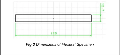
representation of three dimensional surface as an assembly of planar triangles. More number of triangles ensures more accuracy. After conversion into STL file, the slicing of the file includes steps such as 3D description of parts, division of parts into slices, structure for support material and path as well as direction of the tool gets fixed. The STL file is sliced into layers and different parameters are been set according to which the hardware such as nozzle, heater etc. of the machines will operate. FDM samples were created using creality Ender 3 machine having bed size 220 x 220 x 250 mm. Designing of the part and converting it into STL file was done in CATIA software and was further sliced into machine readable g-code file using cura engine of repetier software. The dimension of the tensile specimens were 63.5 x 9.53 x 3.2 mm which are according to ASTM D638 standards. Similarly, the dimensions of impact and flexural specimens are 63 x 12.7 x 3.2 and 125 x 12.7 x 3.2 according to ASTM D256 and ASTM D790 respectively.
————————————————
Vinaykumar S. Jatti , Symbiosis Institute of Technology,
Pune, India. E-mail: vinay.jatti@sitpune.edu.in
Savita V Jatti, D Y Patil College of Engineering, India.
E-mail: savitabirajdardyp@gmail.com
Akshaykumar P. Patel, D.Y. Patil College of Engineering,
Akurdi, Pune
E-mail : akshay030794@gmail.com
Vijaykumar S. Jatti, D.Y. Patil College of Engineering, Akurdi,
Pune
Fig1 Dimensions of tensile specimen.
The material used to create the specimen is polylactic acid(PLA) which is commonly used for FDM processed parts. Uniaxial tensile tests, Izod impact tests, bending tests and surface roughness tester were carried out to determine the tensile strength, impact strength, flexural strength and surface roughness of the specimens were found out using a surface roughness tester. As the tests is perform on the specimens of given standard, the computerised system give the visualise representation of data on the digital screen which is recorded electronically by the machine The process parameters considered are:
1) Layer Thickness – It is the thickness of a single layer that will be deposited by the nozzle. It depends on the type of nozzle used and in this case the nozzle diameter was 0.4 mm. The values for the layer height chosen were 0.08mm, 0.16mm, 0.24mm, 0.32mm and 0.4mm.
2) Print Speed - It signifies the speed of the nozzle in which the material will get deposited. Very high printing speed will lead in improper distribution of materials and wear of physical parts and very low printing speed will a lot of time to print a single specimen. Hence, the values for print speed were set for 20, 35, 50, 65 and 80 mm/sec.
3) Extrusion Temperature – There exist a heater inside the extruder which is used to heat the material upto a semi-liquid state. Hence, the temperature at which the material is extruded from the nozzle is called Extrusion temperature. More the temperature more viscous the material become. Hence, the extruder temperature must be set within the limits where the material can be in semi-liquid state. Extrusion temperature depends on the material used and the capacity of the heater. The set values for temperature were 190, 200, 210, 220, and 230°C.
4) Infill Percentage – The infill percentage states how much material there is inside the fabricated part and hence represents the density of the part. Infill percentage is set according to the requirement of the part. The values for infill percentage taken were 10, 33, 55, 78 and 100 %,
3
RESULTS
AND
DISCUSSIONS
One variable at a time approach was used to study the effect of individual parameters i.e. Infill percentage, print speed, layer height and extrusion temperature on the mechanical properties of 3D printed parts. Five specimens each for tensile, impact and flexural test were developed by changing one parameter at a time and keeping other three parameters constant. The above table shows the constant values taken for other parameters when one of the parameter value was getting varied. After developing all the specimens and carring out the tests, the results obtained is explained in detail below.
.
3.1 Effect of infill percentage on mechanical properties
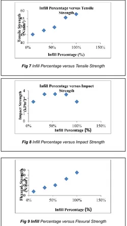
The graphs shows that the tensile, impact and flexural strength increases with increase in infill percentage. It can be understood that tensile strength increases with increase in infill percentage. More infill percentage means more material is been deposited into the fabricated part and hence the density of the part increases. Thus more strength is required to pull and break the specimen. This results in increase of tensile
TABLE1
LIST OF PARAMETERS AND THEIR VALUES Process
Parameters
Constant values
Variable Values
Infill Percentage (%)
50 10,33,55,78,100
Print Speed (mm/s)
50 20,35,50,65,80
Layer Height (mm) 0.2 0.08,0.16,0.24,0.32,0.4
Extrusion Temperature (°C)
210 190,200,210,220,230 Fig 3 Dimensions of Flexural Specimen
Fig 4 Tensile Specimen After Test
Fig 5 Impact Specimen After Test
is an increase in impact strength with increase in infill percentage but the surface roughness is almost constant. Hence there is no effect of infill percentage on the surface roughness of the 3D printed parts. The infill percentage actually affects the amount of material deposited insde the object and hence it has no effect on the materiaals that are been deposited on the outer surface. Thus surface roughness obtained is due to other parameters as the graph of surface
roughness is constant with change in infill percentage 3.2 Effect of Print Speed on mechanical properties
The print speed was varied to 20, 35, 50, 64 and 80 mm/s keeping other three parameters constant. The graphs show that tensile strength and flexural strength are almost unaffected by the print speed. When the object is printed faster, the adhesion between the small filaments constituting the infill is better because the material has had less time to cool down between each passage. This could slightly improve the max strength of the filament. But the increase is almost negligible. At a high speed, the material deposit is less even than it is at a low speed, leading to voids and inaccuracies which can reduce the overall strength of the fabricated part. thus, it cancels out the increase of the strength through adhesion and results in almost constant tensile strength with the change in printing speed. The impact strength and surface roughness increases with increase in layer height. At higher speeds material may not get deposited adequately and hence making the surface quality low which indeed increases the surface roughness of the part.
Fig 7 Infill Percentage versus Tensile Strength
Fig 8 Infill Percentage versus Impact Strength
Fig 9 Infill Percentage versus Flexural Strength
Fig 10 Infill Percentage versus Surface Roughness
Fig 11 Print Speed versus Tensile Strength
3.3 Effect of Layer Height on mechanical properties
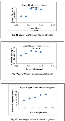
The layer height was varied from 0.08 to 0.4 keeping other parameters constant and it was found that tensile strength decreases with increase in layer height while impact and flexural strength along with surface roughness increases with increase in layer height. The tensile strength of the fabricated part decreases with increase in layer height. Less number of layers means less adhesion and less accuracy of the printed part resulting in decrease in tensile strength. There is a considerable increase in impact and flexural strength since the thickness of the layers will be more and hence these layers will act as a whole rather than providing adhesion. Hence the impaci strength and flexural strength will increase. The material is extruded from the nozzle in a cylindrical manner and hence higher layer height means that two cylindrical shaped materials having higher radius are stacked up one above the other and increases the step like effect, eventually increasing the surface roughness.
3.4 Effect of Extrusion Temperature on mechanical properties
The range of extrusion temperature for PLA is 190 to 230°C. Extrusion Temperature is a temperature at which the material is extruded from the nozzle. This temperature is set at a value where the material is converted into semi-liquid state. With increase in the extrusion temperature the material tends to shift slightly onto liquid state and this results in decrease in viscosity. With a lower viscosity, the extruded material loses its sectional circular shape and it becomes oval. This tends to be somehow useful, since it makes the contact area between layers bigger. Also one can expect that with an increase of temperature, at the end the material tends to become more brittle. Hence, larger contact area tends to increase the strength but the increase is very less. The results indicate Impact strength reduces considerably with increase in extrusion temperature, It is due to the fact that due to less viscosity at higher temperatures the overall thickness of the part reduces which in turn reduces the impact strength. Fig 14 Print Speed versus Surface Roughness
Fig 13 Print Speed versus Flexural Strength
Fig 15 Layer Height versus Tensile Strength
Fig 16 Layer Height versus Impact Strength
Fig 17 Layer Height versus Flexural Strength
4
CONCLUSION
The paper presents the measured value of tensile, impact, flexural and surface roughness properties of 3D printed
effect on impact strength. Maximum Tensile Strength can be obtained at 100% infil, 0.16 mm layer height, 50 mm/s print speed and 220 °C Extrusion temperature. Maximum Impact Strength is obtained at 55% infil, 0.24 mm layer height, 35 mm/s print speed and 190 °C Extrusion temperature Similarly Maximum Flexural Strength is obtained at 100% infil, 0.24 mm layer height, 65 mm/s print speed and 230 °C Extrusion temperature. Minimum surface roughness is achieved at 55% infil, 0.08 mm layer height, 20 mm/s print speed and 210 °C Extrusion temperature.
REFERENCES
[1] SH Masood, ―Advances in Fused Deposition Modeling‖, Swinbume University of Technology, Melbourne, VIC, Australia. © Elsevier 2014.
[2] Dudescu Cristian, ―Effects Of Raster Orientation, Infill Rate And Infill Pattern On The M echanical Properties Of 3d Printed Materials‖, Acta Uiversitatis Cibiniensis – Technical Series Vol. Lxix 2017 © 2017 ―Lucian Blaga‖ University Of Sibi
[3] João Fernandes, Marco Leite, Augusto dues, Luis Reis, M.F. Vaz, ―Study Of The Influence Of 3d Printing Parameters On The Mechanical Properties Of Pla‖, 3rd International Conference on Progress in Additive
[4] Manufacturing (Pro-AM 2018) 14-17 May 2018, Singapore.
[5] Friedrich Bahr, Engelbert westcamper, ―Correlations between Influencing Parameters and Quality Properties of Components Produced by Fused Deposition Modeling‖, 51st CIRP Conference on Manufacturing Systems, © 2018 The Authors. Published by Elsevier B.V.
[6] Ngoc-Hien Tran, Nam Nguyen, Anh-Vu Ngo, Van-Cuong Nguyen, ―Study on the Effect of Fused Deposition Modeling (FDM) Process Parameters on the Printed Part Quality‖, Ngoc-Hien Tran. Int. Journal of Engineering Research and Application ww.ijera.com ISSN : 2248-9622, Vol. 7, Issue 12, ( Part -2) December 2017, pp.71-77.
[7] Pritish Shubham, Arnab Sikidar and Teg Chand, ―The Influence of Layer Thickness on Mechanical Properties of the 3D Printed ABS Polymer by Fused Deposition Modeling‖, Key Engineering Materials Submitted: 2016-04-09, ISSN: 1662-9795, Vol. 706, pp 63-67, © 2016 Trans Tech Publications, Switzerland.
[8] WenzhengWu, Wenli Ye, Zichao Wu , Peng Geng, Yulei Wang and Ji Zhao, ―Influence of Layer Thickness, Raster Angle, Deformation Temperature and Recovery Temperature on the Shape-Memory Effect of 3D-Printed Polylactic Acid Samples‖, School of Mechanical Science and Engineering, Jilin University, Renmin Street 5988, Changchun 130025, China.
Fig 19 Extrusion temperature versus Tensile Strength
Fig 20 Extrusion temperature versus Impact Strength
Fig 19 Extrusion temperature versus Flexural Strength


