DESIGN, DEVELOPMENT AND TESTING OF CROSS
FLOW CIRCULAR HEAT PIPE TO COOLING OF OIL
Vishnupant J. Sargar
1, Pruthveeraj D. Mali
21,2
Asst. Prof. Department of Mechanical Engineering, Adarsh Institute of Technology
& Research Center, Vita Shivaji University, Kolhapur, (India)
ABSTRACT
Heat pipes are very flexible device to effective thermal control. It can easily be implemented for heat removing of hydraulic oil. In power pack application, hot oil is passed through four modules of the heat pipe. In heat pipe, heat is removed from oil and cold fluid is returned to the reservoir. The working fluid as water in the heat pipes respond to the application of heat by boiling, changing into a gaseous state, and transporting the heated gas to the pipe ends exposed to air. Ambient air is drawn over the exposed pipe by using blowers, causing the working fluid to condense and return to the heat source (the hot oil) to repeat the process. As long as there is a temperature difference between the oil and the ambient air, the heat pipes will remove heat from the oil, thus cooling is done. In the case of Hydraulic oil coolers- heat is removed from oil into the ambient air through heat pipes and fins.This paper reviews mainly heat pipe developments for cooling of oil for various applications like power pack, roasting pulp and chemical industries etc.
Keywords: Blower; Circularheat Pipe; Fins; Pump.
I. INTRODUCTION
Heat pipe are effective heat transfer device which have found many application in industry. A heat pipe
is essentially a passive heat transfer device with an extremelyhigh effective thermal conductivity.Heat pipes are
transport heat from a heat source (evaporator) to heat sink (condenser) over relatively long distance via latent
heat of vaporization of working fluid.With evaporator section, the working fluid is evaporated as it
absorbs an amount of heat equivalent to the latent heat of vaporization, while in the condenser section; the
working fluid vapour of condensed. Return of liquid to the evaporator from the condenser is provided by the
wick structure. The two-phase heat transfer mechanismresults in heat transfer capabilities from one hundred to
several thousand timesthat of an equivalent piece of copper.There are many factors to consider when designing a
heat pipe: compatibilityof materials, operating temperature range, diameter, power limitations, thermal
resistances, and operating orientation.The most important heat pipe design consideration is the amount of power
theheat pipe is capable of transferring. Heat pipes can be designed to carry a fewwatts or several kilowatts,
depending on the application. Heat pipes cantransfer much higher powers for a given temperature gradient than
even the bestmetallic conductors. If driven beyond its capacity, however, the effectivethermal conductivity of
the heat pipe will be significantly reduced. Therefore, it is important to assure that the heat pipe is designed to
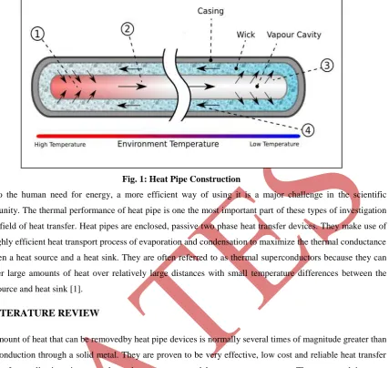
Fig. 1: Heat Pipe Construction
Due to the human need for energy, a more efficient way of using it is a major challenge in the scientific
community. The thermal performance of heat pipe is one the most important part of these types of investigation
in the field of heat transfer. Heat pipes are enclosed, passive two phase heat transfer devices. They make use of
the highly efficient heat transport process of evaporation and condensation to maximize the thermal conductance
between a heat source and a heat sink. They are often referred to as thermal superconductors because they can
transfer large amounts of heat over relatively large distances with small temperature differences between the
heat source and heat sink [1].
II. LITERATURE REVIEW
The amount of heat that can be removedby heat pipe devices is normally several times of magnitude greater than
pure conduction through a solid metal. They are proven to be very effective, low cost and reliable heat transfer
devices for applications in many thermal management and heat recovery systems. They are used in many
applications including but not limited to passive ground/road anti-freezing, baking ovens, heat exchangers in
waste heat recovery applications, water heaters and solar energy systems and are showing some promise in
high-performance electronics thermal management for situations which are orientation specific [2].Thermal energy
devices such as heat pipes and thermo syphon possess many advantages such as high heat recovery
effectiveness, high compactness, no moving parts, and high reliability. Kasperski et al. [3]studied
thermo-hydraulic analysis of a solar air heater with an internal multiple-fin array. A preliminary simple test was carried
out to confirm the efficiency enhancement of the proposedarrangement.Multiple fin-array technology enables to
decrease the demanded air flux of 7e10 times incomparison to the smooth pipe arrangement of the
absorber.Multiple-fin array arrangement is higher than the one available for smooth pipe arrangement. Jarallah
et al. [4]the performance of a triple concentric pipe heat exchanger is studied experimentally under steady state
conditions for two different flow arrangements, called N–H–C and C–H–N, and for insulated as well as
non-insulated conditions of the heat exchanger.Since the 1970s, heat pipes and thermo syphon have been extensively
applied as waste heat recovery systems in many industries such as energy engineering, chemical engineering,
and metallurgical engineering. The heat pipe has been, and currently is being, studied for a wide variety of
applications, covering almost the complete spectrum of temperatures encountered in heat transfer processes. The
ability of the heat pipe to transport heat over appreciable distances without any need for external power to
supply leads to greater reliability of the heat transport system and reduced weight, in addition to the saving in
power consumption (Silverstein 1992).
III. MAINTAINING STABLE HYDRAULIC OIL TEMPERATURE
Heating of hydraulic fluid in operation is caused by inefficiencies. Inefficiencies result in losses of input power,
which are converted to heat. A hydraulic system’s heat load is equal to the total power lost (PL) through
inefficiencies and can be expressed as:
PLTotal =PLPump+ PLValves + PLPlumbing + PLActuators (1)
If the total input power lost to heat is greater than the heat dissipated, the hydraulic system will eventually
overheat. Installed cooling capacity typically ranges between 25 and 40percent of input power, depending on the
type of hydraulic system. Hydraulic fluid temperatures above 180°F (82°C) damage most seal compounds and
acceleratedegradation of the oil. While the operation of any hydraulic system at temperatures above 180°F
should be avoided, fluid temperature is too high when viscosity falls below the optimum value for the hydraulic
system’s components. This can occur well below 180°F, depending on the fluid’s viscosity grade. The hydraulic
power unit had a continuous power rating of 37 kWand was fitted with an air-blast heat exchanger. The
exchanger was capable of dissipating10 kW of heat under ambientconditions or 27 percent ofavailable input
power (10/37 x 100 = 27). Hydraulic systems dissipate heat through the reservoir. Therefore, check the reservoir
fluid level and if low, fill to the correct level. Check that there are no obstructions to airflow around the
reservoir, such as a buildup of dirt or debris. The ability of the heat exchanger to dissipate heat is dependent on
the flow-rate and temperature of both the hydraulic fluid and the cooling air or water circulating through the
exchanger. Where there is a pressure drop, heat is generated. This means that any component in the system that
has abnormal, internal leakage will increase the heat load on the system and can cause the system to overheat.
This could be anything from a cylinder that is leaking high-pressure fluid past its piston seal, to an incorrectly
adjusted relief valve. Identify and change-out any heat-generating components.Check the performance of all
cooling circuit components and replace as necessary. An infrared thermometer can be used to check the
performance of a heat exchanger, provided the design flow-rate of hydraulic fluid through the exchanger is
known. To do this, measure the temperature of the oil entering and exiting the exchanger and substitute the
values in the following formula to find the heat removed from the oil:
(2)
Where, Q is Rate of Heat Removing in KJ/s;
is Mass flow rate in Kg/s;
is Specific heat of the oil in KJ/Kg.K;
is Temperature difference of inlet oil and outlet oil in oK.
IV. PROPOSED SOLUTION FOR COOLING OF OIL: CIRCULAR HEAT PIPE WITH
BLOWER
The experimental set up is shown in the Fig.2;four heat pipe modules are used to remove the heat from the
fluidwhich is connected in parallel. The spiral radial heat fins are attached on the heat pipe module act as heat
transfer enhancement as they offer maximum surface area in the given space. The concept of the heat pipe
The radial blower (12 volt DC) takes cold air in the system in axial direction and discharges it in radial
direction. This cold air is then directed on to the spiral radial fins mounted on the four heat pipe modules. The
hot oil is passed in the system with help of hydraulic pump whereas the cold oil from the proposed system is
discharged back to the oil reservoir. This oil cooling system can be mounted externally to the oil tank system
thereby ensuring contamination free operation as the oil tank is sealed.
The heat pipe functions[1] are as follows
1. Latent heat of evaporation is absorbed in the evaporating section.
2. The fluid boils to the vapour phase.
3. The vapour release latent heat of condensation to the environment from the upper part of the pipe and
condensers.
4. Condensed liquid returns by the capillary action to the evaporator part of cylinder (evaporating
section). When heat is added to the evaporator section, the working fluid boils and converts into vapour
absorbing latent heat. After reaching the condenser section, due to partial pressure build up, the vapour
transform back into the liquid thus releasing latent heat. From the condenser section, heat is taken away by
means of water cooling /air cooling with fins etc. The liquidcondensate returns to the original position
through the capillary return mechanism, completing the cycle. Due to very high latent heat of vaporization a
large quantity of heat can be transferred.
The heat pipe used in the module has following specifications:
a) Type: Short cylindrical heat pipe
b) Material: Copper
c) Working fluid: Water
Fig. 2 Experimental Set Up For Cooling Of Oil By Circular Heat Pipe
V. RESULT AND DISCUSSION
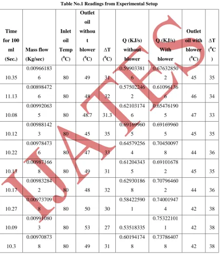
With the help of above experimental set up, tests were performed to investigate the performance of heat pipe
with blower and without blower. The tests are taken for different mass flow rate and find out the heat removal
rate by using the equation no.2. This is tabulated below in Table No.1.
Table No.1 Readings from Experimental Setup
Time
for 100
ml
(Sec.)
Mass flow
(Kg/sec)
Inlet
oil
Temp
(
0C)
Outlet
oil
withou
t
blower
(
0C)
∆T
(
0C)
Q (KJ/s)
without
blower
Q (KJ/s)
With
blower
Outlet
oil with
blower
(
0C)
∆T
(
0C
)
10.35
0.00966183
6
80
49
31
0.59903381
6
0.67632850
2
45
35
11.13
0.00898472
6
80
48
32
0.57502246
2
0.61096136
6
46
34
10.08
0.00992063
5
80
48.7
31.3
0.62103174
6
0.65476190
5
47
33
10.12
0.00988142
3
80
45
35
0.69169960
5
0.69169960
5
45
35
10.22
0.00978473
6
80
47
33
0.64579256
4
0.70450097
8
44
36
10.13
0.00987166
8
80
49
31
0.61204343
5
0.69101678
2
45
35
10.17
0.00983284
2
80
48
32
0.62930186
8
0.70796460
2
44
36
10.27
0.00973709
8
80
50
30
0.58422590
1
0.74001947
4
42
38
10.09
0.00991080
3
80
53
27
0.53518335
0.75322101
1
42
38
10.3
0.00970873
8
80
49
31
0.60194174
8
0.73786407
8
42
38
From the above table we conclude that the heat removal rate in case of with blower circular heat pipe system is
The graphs are plotted as mass flow rate verses heat transfer rate, overall heat transfer coefficient, it is shown in
Fig. 3. The graph shows that the effect of blower on the heat removal rate is better than without the blower.
Fig.3 Variation of Overall Heat Transfer Coefficient and Heat Transfer Rate
VI. CONCLUSION
The circular heat pipe with blower achieves significantheat removal rate as compare to without blower. The
temperature difference is achieved about 5 oC more than the without blower system. The require energy for the
blower is very less as considering the temperature difference of the fluid which is achieved. So that we conclude
that the heat pipe with blower is more effective to reduce the temperature of fluid.
REFERENCES
[1]. C.R.Kamthane, P.M.Khanwalkar, “Development of Enhanced Cross Flow Heat Pipe Hydraulic Oil Cooler”,
International Journal of Pure And Applied Research In Engineering And Technology, Volume 2(9)
:218-228
[2]. David Reay and Peter Kew, “Heat Pipes Theory, Design And Applications”, Fifth Edition, B.H.
Publication, pp 5-95.
[3]. Leonard L. Vasiliev, “Heat pipes in modern heat exchangers”, Applied Thermal Engineering 25 (2005) 1–
19.
[4]. William Ryan Parrish, “Hydraulic Radiant Cooling”,BCN 6586Spring 2006.
[5]. JacekKasperski and Magdalena Nem, “Investigation of thermo-hydraulic performance of concentrated solar
air-heater with internal multiple-fin array”, Applied Thermal Engineering 58 (2013) 411-419.
[6]. G.A. Quadir and SaqabS.Jarallah, “Experimental investigation of the performance of a triple concentric
[7]. Y. Alyousef, “Three adsorbers solar cooler with composite sorbent bed and heat pipe thermal control”,
Applied Thermal Engineering 38 (2012) 124-130.
[8]. Guy Diemunsch, “Cooling to keep your Key Chips Alive”, 70 Commercial Street, Suite 200Concord, NH