IJEDR1804041
International Journal of Engineering Development and Research (
www.ijedr.org
)
215
Behavior of Rectangular RC Columns Confined
with BFRP sheets Subjected to Axial Loading
1
Yehia A. Kotp,
2Omar A. Farghal,
3Mohammed F. M. Fahmy
1Demonstrator, 2Associate Professor, Associate Professor3Civil Engineering Department,
1 Faculty of Engineering, Al-azhar University, Quena, Egypt
_____________________________________________________________________________________________________
Abstract— In this paper an investigation on the behavior of short rectangular reinforced concrete columns wrapped
with fiber reinforced polymer (FRP) sheets under axial compression loading was conducted. This study aims at experimentally evaluating the performance of these strengthened columns by using a new promising FRP material (Basalt fiber reinforced polymer (BFRP)) sheets. Moreover, it aims to investigate the limit of the cross-sectional aspect ratio parameter which has been the subject of controversial for the last two decades. Hence, eight RC columns with aspect ratios (1.0, 1.5, 2.0 and 2.5) were tested .The behavior of columns in the axial and transverse directions was analyzed. After that, some existing confinement models for rectangular RC columns were used to predict the nominal compressive strength of rectangular RC BFRP –confined columns sheets. From this research, it can be concluded that, using BFRP sheets in confining of RC columns increases the carrying capacity and ductility. Also, the limit of the aspect ratio at which the gained strength becomes insignificant is 2.0. Finally, the model of Wang and Hsu [1] has a good agreement to predict the nominal compressive strength of rectangular RC columns strengthened with BFRP sheets.
Index Terms—Reinforced concrete columns, aspect ratio, FRP, Basalt fiber reinforced polymer (BFRP), full wrapping.
_____________________________________________________________________________________________________
I.INTRODUCTION
Over the past decades, FRP composites have proved to be alternative method for strengthening concrete structures instead of steel due to their good engineering properties such as negligible thickness besides high strength and high corrosion resistance. Besides that, they preserve the architectural view. Regarding an important structural element such as column, FRP materials have successfully improved the behavior of circular concrete columns with a geometrical structure that allows the fibers to be uniformly stressed. Consequently, this provides a highly effective confinement for concrete core across the entire cross-section. The confinement effectiveness for rectangular columns is lower than circular sections because of the non-uniformity of the confinement pressure across the cross-section. Moreover, the effectiveness of rectangular concrete columns confinement depends on several parameters. One of these parameters is the geometry of the cross section including the aspect ratio of cross-section, corner radius, and size of specimens.
Most researches focused on rectangular concrete columns wrapped with FRP sheets with cross sectional aspect ratios less than 1.5. As a result, ACI 440.2R-02 [2] set a maximum aspect ratio (t/b) =1.5 and strengthening of rectangular concrete columns confined with FRP sheets can be neglected if the aspect ratio exceeds this limit unless demonstrated by experimental evidence. But in the updated version of the ACI 440.2R-08 [3], the limitation of the aspect ratio was extended to 2.0. Moreover, Analytical studies on plain concrete conducted by Wu and Wei [4] indicated that confinement becomes insignificant when the aspect ratio reaches 2.0. However, Tan [5], Alsayed et al. [6], and Triantafillou et al. [7] found that wrapping fiber sheets increased the axial strength of rectangular RC columns even with aspect ratios higher than 3.00.
Basalt fiber reinforced polymer (BFRP) is a new promising engineering material as stated by Zhishen et al. [8]. Despite that, few papers discussed strengthening the concrete members with BFRP sheets; Liu et al. [9] and De Luca et al.[10]. So, it is necessary to investigate the axial compression behavior of RC rectangular columns experimentally and analytically, focusing on the effect of the cross-sectional aspect ratio.
The main objective of this paper is to measure the range of the cross-sectional aspect ratio of concrete columns confined by using BFRP sheets in the presence of longitudinal and transverse steel. In addition to that, the existing analytical models were used to predict the nominal compressive strength of rectangular RC columns confined with BFRP sheets.
II.EXPERIMENTAL PROGRAM
The experimental investigation was done to evaluate the effect of the aspect ratio of the cross-section on the axial behavior of BFRP-confined RC rectangular column. So, failure modes, load carrying capacity and the longitudinal and transverse strains of the specimens were investigated.
Test Specimens and Designation
IJEDR1804041
International Journal of Engineering Development and Research (
www.ijedr.org
)
216
aspect ratio of the cross section of the column. The designation of BFRP-confined columns had two parts. The first part refers to the type of fiber which was B that refers to basalt FRP. The second part was a number (1.0, 1.5, 2.0, or 2.5) which is the aspect ratio of the cross section.Materials
Ordinary portland cement (OPC) was used with a water-cement ratio of 0.53 to achieve concrete cube strength of 25 MPa. The concrete mix had proportions of: 1.00: 1.74: 3.35 for cement, fine aggregate (siliceous sand) and coarse aggregate (gravel) respectively. Woven unidirectional Basalt fiber sheets were used for jacketing, and two-part Sikadur-330 epoxy impregnation resin was used as adhesive. BFRP properties extracted from the flat coupon test were; 0.157 mm/ply for the nominal thickness (tf), 2.1% for the ultimate tensile strain (ɛfu) and 92 GPa for the elastic modulus (Ef ).
Fabrication of Test Specimens
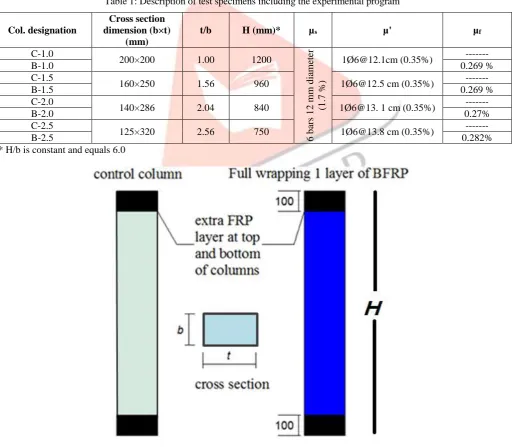
The specimens were fabricated in two stages: the first stage was the fabrication of eight RC specimens, and the second stage was the application of BFRP sheets for four specimens with one layer. Additional BFRP layer was added at the top and bottom of the columns to avoid any premature failure, as shown in Fig. 1 and Fig. 2.
As soon as the concrete had reached an age of 28 days, BFRP sheets were wrapped around the column’s cross-section. Before the application of BFRP sheets, concrete surface was prepared using a hammer and blower to remove the week elements on the concrete cover. Then, the epoxy paste, Sikadure-41, was applied on the column surface to fill the irregulations and the surface of the epoxy paste was smoothed. BFRP sheets were applied on the concrete surface using epoxy resin, Sikdu-330. BFRP sheets were used in one layer for the total clear height of the column. A special roller was used to attach the BFRP sheets to ensure that the FRP is saturated with the epoxy resin and there is no air voids between the fibers and the concrete surface as well.
Table 1: Description of test specimens including the experimental program
Col. designation
Cross section dimension (b×t)
(mm)
t/b H (mm)* µs µ' µf C-1.0
200×200 1.00 1200
6
b
ar
s
1
2
m
m
d
ia
m
eter
(1
.7
%)
1Ø[email protected] (0.35%) ---
B-1.0 0.269 %
C-1.5
160×250 1.56 960 1Ø[email protected] cm (0.35%) ---
B-1.5 0.269 %
C-2.0
140×286 2.04 840 1Ø6@13. 1 cm (0.35%) ---
B-2.0 0.27%
C-2.5
125×320 2.56 750 1Ø[email protected] cm (0.35%) ---
B-2.5 0.282%
* H/b is constant and equals 6.0
IJEDR1804041
International Journal of Engineering Development and Research (
www.ijedr.org
)
217
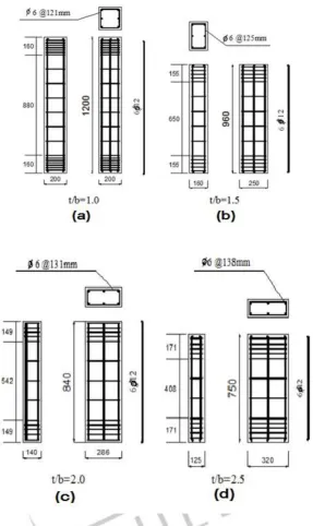
Figure 2: Arrangement of internal reinforcement of columns of different aspect ratios (t/b): (a): t/b=1.0, (b):t/b=1.5,(c):t/b=2.0 and (d):t/b=2.5
Instrumentation and Testing
To measure the axial and transvers strains along the height of the specimens, LVDT and electrical strain gauges were used. Universal testing machine with 5000 kN capacity were used to test the column specimens under axial compression. The axial load, vertical displacement, lateral expansion, and strains were recorded by Data Logger System (DLS).
Analysis and Discussion of Test Results
Observed Failure Modes
IJEDR1804041
International Journal of Engineering Development and Research (
www.ijedr.org
)
218
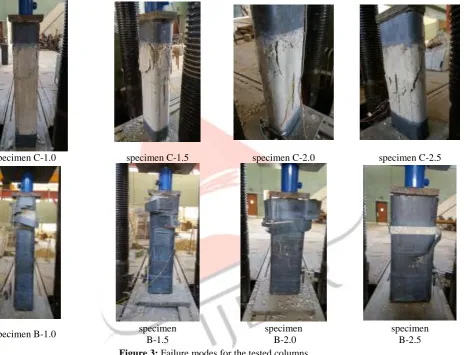
strengthened columns the BFRP sheets at the mid-height of the columns were bulging. This observation indicates that the failure occurred due to crushing of concrete and buckling of longitudinal steel. However, this bulging and the rupture of FRP sheets was the main cause of failure. This result also expresses the distinguished attendance with competence of the confinement by BFRP sheets which caused delaying of steel yielding. It was also noticed that the explosion was accompanied with scattered fragments of concrete. It is worthwhile to note that, no premature local failure was observed around the end portions of the specimens. The typical failure modes of the specimens are shown in Fig.3.Compressive Strength
The compressive strengths for the different columns are illustrated in Table 2, from which it can be noticed that, confinement with BFRP wraps increased the compressive strength significantly particularly, in case of lower aspect ratio. The increase in aspect ratio resulted in a decrease in axial load capacity. The Increase percentage in the strength reached its minimal value at higher aspect ratio of 2.56. The maximum increases were achieved in the case of square columns, which showed 34% increase in comparison with the corresponding reference column. It was also noticed that, there has been considerable variation in the value of (f’cc /fc). This indicates that the size of specimen plays an important role on the value of the gained strength.
specimen C-1.0 specimen C-1.5 specimen C-2.0 specimen C-2.5
specimen B-1.0 specimen
B-1.5
specimen B-2.0
specimen B-2.5
Figure 3: Failure modes for the tested columns
.
Table 1: Effect of strengthening on the carrying capacity
Specimen
ID fc(MPa) pu(kN) f'cc(MPa)* f'cc /fc
Specimen
ID fc(MPa) pu(kN) f'cc(MPa) f'cc /fc
Increase percentage %**
C-1.0 24.32 828 20.70 0.85 B -1.0 25.72 1107 27.68 1.08 33.72
C-1.5 28.96 812 20.30 0.70 B -1.5 27.20 1002 25.05 0.92 23.40
C-2.0 25.36 731 18.28 0.72 B -2.0 23.56 850.5 21.26 0.90 16.30
C-2.5 27.36 727 18.18 0.66 B -2.5 24.88 785 19.63 0.79 8.00
*
where; fc: the compressive concrete strength for the standard cube, f’cc peak nominal strength of RC columns,∗∗ Increase percentage % = 𝑓′𝑐𝑐 𝐵𝐹𝑅𝑃−𝑐𝑜𝑛𝑓𝑖𝑛𝑒𝑑 𝑐𝑜𝑙𝑢𝑚𝑛− 𝑓′𝑐𝑐 𝑅𝑒𝑓𝑒𝑟𝑒𝑛𝑐𝑒 𝑐𝑜𝑙𝑢𝑚𝑛 𝑓′𝑐𝑐 𝑅𝑒𝑓𝑒𝑟𝑒𝑛𝑐𝑒 𝑐𝑜𝑙𝑢𝑚𝑛
IJEDR1804041
International Journal of Engineering Development and Research (
www.ijedr.org
)
219
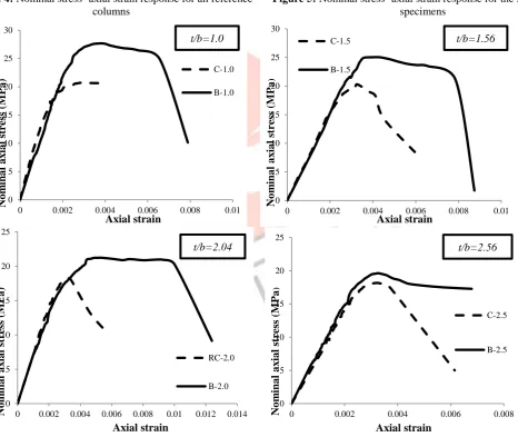
The typical axial stress-axial strain curves for different specimens are shown in Figs. 4 and 5. Figure 4 shows axial strain response for the reference columns whereas Figure 5 shows axial strain response for the strengthened columns. Figure 6 shows axial strain response for a different aspect ratio. The data of the axial strains were collected by LVDT. By analyzing Figure 4 it is clear that, the behavior of RC square reference column was different from that of rectangular reference columns, especially for initial axial stiffness. The square one had a higher initial stiffness. This might be attributed to the more uniform passive stress from transvers steel hoop than those of t/b higher than 1.00. Also, for the same reason, the reference square RC column had the highest value of compressive strength (f’cc). In a similar way, the initial axial stiffness decreased by increasing (t/b) but the influence was insignificant. For the (t/b ˃1.56) specimens, the initial stiffness had almost the same slope because the passive pressure by transverse steel was minimal.By analyzing Fig. 5 it is found that, confinement of columns with BFRP can enhance the performance of concrete columns. It is obvious from the figure that sufficiently confining columns with BFRP sheets can exhibit high ductile behavior. Additionally, the BFRP wrapping was more effective in square section than that of rectangular one. Also, as the aspect ratio increased the ultimate confined strength decreased. On contrast, the ultimate strain increased with the increase of the aspect ratio. Because of the higher value of corner radius (rc=40mm) all strengthened columns exhibited a minor softening behavior. It can be seen from Fig. 6 that, the strengthening with BFRP sheets did not affect the initial stiffness of the column. On the level of service load, the wrapped columns had a contribution to the service stress and decreased with increasing the aspect ratio. Finally, it was verified that the specimen B-2.5 showed insignificant effect on the strength by considerable effect on the ductility.
Table 3 summarizes ultimate lateral strains of BFRP-wrapped specimens ɛut for both directions. The data of lateral strains for both sides at the mid-height of the BFRP wrapped columns were measured using electrical strains gauges. Also, Table 3 shows average maximum lateral strains ɛav ut and the ratio kɛ which indicates the ratio between the average lateral strain ɛav ut and the rupture strain of BFRP provided by the flat coupon test (ɛf =2.1%). The obtained results concerning the ratio kɛ indicated that, the effectiveness of BFRP wrapping strengthening system was affected considerably by the cross-sectional aspect ratio t/b. Consequently, the FRP strengthening system worked in its optimum performance in case of square sections, although the value of measured maximum was lower than that of ultimate strain given by manufacturer. Besides that, the values of maximum lateral strains on the longer side were less than those on the shorter side. Moreover, it was noticed that, the maximum lateral strains on both short and long side generally decreased as the aspect ratio increase. So, kɛ is clearly affected by the aspect ratio value. The maximum lateral strains for column of higher aspect ratio (t/b=2.56) were very small in comparison with that of lower aspect ratio. This indicated that the fiber could not provide a significant passive pressure to delay the yielding of longitudinal bars and resist buckling.
Effect of the Aspect Ratio of the Cross-Section
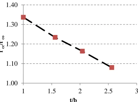
Table 4 shows the values of the compressive strength and the corresponding gained strength for the confined columns f’cc/f’co, where f’cc is the compressive strength of the FRP-confined concrete columns and f’co is the compressive strength of the reference columns. It is clear from this table that, the BFRP-confined column with square cross-section (t/b=1.00), showed a significant improvement in the compressive strength in comparison with those of higher aspect ratios. f’cc/f’co for the rectangular specimens with the higher aspect ratio of 2.56 was the smallest one (=1.08). This meant that there was no significant gained strength at this case. The relationship between the gained strength of the confined concrete and the aspect ratio (t/b) is shown in
Fig. 7. From this figure, it can be concluded that, by increasing the aspect ratio, the compressive strength decreases. It is interesting to note that, the relation between (f’cc/f’co) and the aspect ratio (t/b) was approximately linear.
Table 2: Values of the ultimate lateral strains of BFRP
Specimen ID ɛut average (ɛav ut) kɛ=ɛav ut/ɛf
At short side At long side
B-1.0 0.0164 0.0164 0.0164 0.78
B-1.5 0.0191 0.0095 0.0143 0.68
B-2.0 0.0162 0.00662 0.01141 0.54
B-2.5 0.0056 0.00422 0.00491 0.23
Table 3: Compressive strength and corresponding f’cc/f’co
Aspect ratio ( t/b)
f’co
(MPa)
f'cc of BFRP
(MPa) f'cc/f’co
1.00 20.70 27.68 1.34
1.54 20.30 25.05 1.23
2.04 18.28 21.26 1.16
IJEDR1804041
International Journal of Engineering Development and Research (
www.ijedr.org
)
220
Figure 4: Nominal stress- axial strain response for all reference columns
Figure 5: Nominal stress- axial strain response for the strengthened specimens
Figure 6: Nominal stress-axial strain response for a different aspect ratio of t/b
0 5 10 15 20 25
0 0.002 0.004 0.006 0.008
No m ina l a x ia l st re ss ( M P a ) Axial strain C-1.0 C-1.5 C-2.0 C-2.5 0 5 10 15 20 25 30
0 0.005 0.01 0.015
No m ina l a x ia l st re ss ( M P a ) Axial strain B-1.0 B-1.5 B-2.0 B-2.5 0 5 10 15 20 25 30
0 0.002 0.004 0.006 0.008 0.01
No m in a l a x ia l st ress ( M Pa ) Axial strain C-1.0 B-1.0 t/b=1.0 0 5 10 15 20 25
0 0.002 0.004 0.006 0.008 0.01 0.012 0.014
No m in a l a x ia l st ress ( M Pa ) Axial strain RC-2.0 B-2.0 t/b=2.04 0 5 10 15 20 25 30
0 0.002 0.004 0.006 0.008 0.01
No m ina l a x ia l st re ss ( M P a ) Axial strain C-1.5 B-1.5 t/b=1.56 0 5 10 15 20 25
0 0.002 0.004 0.006 0.008
IJEDR1804041
International Journal of Engineering Development and Research (
www.ijedr.org
)
221
Figure 7: Gained strength of BFRP-confined column versus aspect ratio of (t/b)
III.ANALYTICAL MODELING
Existing Confining Models for RC Rectangular BFRP-confined Columns
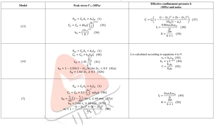
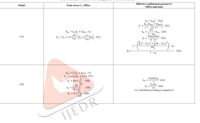
Confinement with FRP jackets enhances the axial compressive strength of different concrete elements and increases confined concrete strength f’cc, and consequently axial column strength. So, the axial compressive strength of non-slender RC columns confined with wrapped BFRP sheets (Pan) may be calculated using confined concrete strength f’cc according to existing models summarized in Tables 5 to 8.
Evaluation of Existing Models
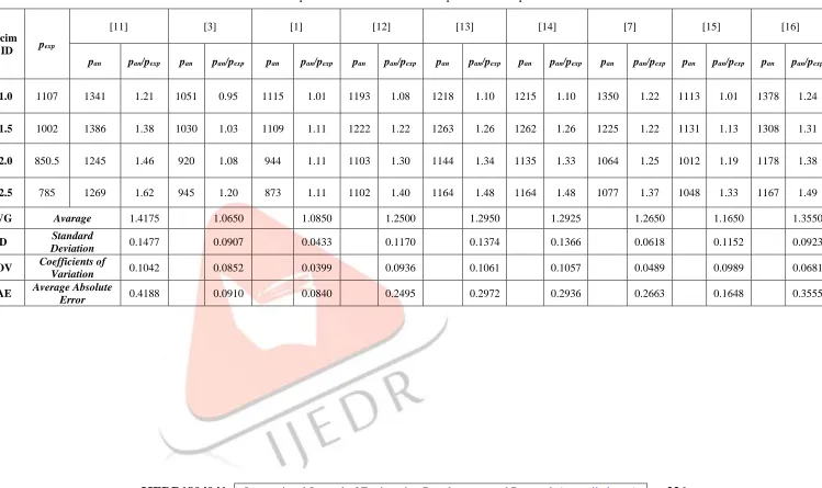
The existing analytical models for BFRP-confined RC rectangular columns described in Tables 5 to 8 were used to calculate the nominal compressive strength of the BFRP-confined columns (Pan). The average ratios between analytical and experimental strengths (AVG), the coefficients of variation (CoVs), standard deviation (SDs) and average absolute error (AAEs) were calculated to evaluate the performance of these analytical models, as shown in Table 9.
Table 9 shows detailed comparisons of the predicted compressive strength (Pan) and the experimental strength (Pexp) of the tested columns. The different studied models approximately overestimated the compressive strength of BFRP-confined columns except that proposed by ACI 440.2R-08 [3] which also underestimated in case of lower aspect ratio (t/b=1.0). Wang and Hsu model was to some extent the accurate model to predict the peak strength. From Table 9, Wang and Hsu [1] model achieved the smallest values of standard deviation, coefficient of variation ratio and average absolute error. So, Wang and Hsu [1] model conservatively predicted the compressive strength. In case of the analytical model proposed by Wang and Hsu [1], there was somewhat a good agreement between the predicted calculation and the corresponding experimental results. Actually, the accuracy of available analytical models for FRP-confined rectangular RC columns should be verified with additional test results reflecting the effects of different design parameters for the general applications in predicting the compressive strength of FRP-confined rectangular RC columns. This will be presented in the near future by the authors.
IV.CONCLUSIONS
The experimental study presents an investigation of the behavior of axially loaded short rectangular RC columns strengthened with BFRP sheets. Moreover, existing analytical models were used to predict the nominal compressive strength for the strengthened columns. The findings from this work can be summarized as follows.
• Using BFRP sheets in confining RC short columns increases the load carrying capacity and ductility, particularly in case of lower aspect ratio (t/b =1.0) hence f’cc/f’co=1.34 in that case.
• As the aspect ratio of the cross section increases, the strength gained of confined concrete columns decreases until it becomes insignificant at an aspect ratio of higher than 2.04.
• Using BFRP tends to increase the ductility. The ductility increases by increasing the aspect ratio of the rectangular cross sections.
• Wang and Hsu, 2008 model gives a good estimation for the BFRP wrapped rectangular RC columns and proves the efficiency of the proposed model with AVG=1.085, SD=0.0433, CoV=0.0399 and AAE=0.0840.
• More data are needed to:
a) Experimentally study the performance of BFRP reinforced concrete column under combined axial-flexural loading. b) Propose axial stress-strain model of FRP confined concrete under monotonic and cyclic loading from which axial design strength of FRP-confined full-scale rectangular RC columns with different cross-sectional aspect ratios can be extracted.
1.00
1.10
1.20
1.30
1.40
1
1.5
2
2.5
3
f'cc
/f
'co
IJEDR1804041
International Journal of Engineering Development and Research (
www.ijedr.org
)
222
Table 4: Summary of models for RC rectangular cross sections.Model Peak stress f’cc (MPa) Effective confinement pressure fl
(MPa) and notes
[11]
Pan= fcc′ Ac+ Asfyl (1)
fcc′ = fco′ + k1fl (2)
Where; k1= 1.25√ fco′
fl (3)
hence 2.00 ≤ k1≤ 7.00
fl= flf+ fls
Acc
Ag
(4)
flf=
kfμfEfεf
2 (5)
fls=
ksμ,fys
2 (6)
μf=
2nftf(b + t)
bt (7)
kf= 1 −
(b − 2rc)2+ (t − 2rc)2
3bt(1 − μs)
(8)
ks=
1 (1 − μsc)2
(1 − s′
2b′) (1 − s′
2t′) (1 − ( 1
6b′t′) ∑ wxi
2 + w
yi 2) (9)
εf= 0.6 εfu for case of CFRP or GFRP
εf= 0.85 εfu for case of AFRP
[3]
Pan=∝ [0.85 fcc′ Ac+ fylAs] (10)
take ∝ here = 1.00 fcc′ = fco′ + 3.3ψfkafl (11)
ψf is an additional reduction factor and is given as equal to 0.95
ka= (
b t)
21 − (
b
t(t − 2rc)2+bt(b − 2rc)2
3Ag ) − μs
1 − μs
(12)
fl=
2nftfEfεf
D (13)
D = √t2+ b2 (14)
IJEDR1804041
International Journal of Engineering Development and Research (
www.ijedr.org
)
223
Table 5: Summary of models for RC rectangular cross sections (continue).Model Peak stress f’cc (MPa) Effective confinement pressure fl
(MPa) and notes
[1]
pan= (0.3fc′Acu+ fcc.j′ Acj+ fcc.js′ Acjs) + fylAs (15)
fcc′ =∝1∝2fc′ (13)
∝1= 1.25 (1.8√1 + 7.94
F1
fc′
− 1.6F1 fc′
− 1) (16)
∝2= 1 + [1.4
f1
F1
− 0.6 (f1 F1
)
2
− 0.8] √F1 fc′
(17)
Acu= Ac− Ae,j (18)
Acj = Ae,j− Ae,s (19)
Ac= bt − As− rc2(4 − π) (20)
Ae,j= Ac− (
(t − 2rc)2+ (b − 2rc)2
3 ) (21)
Acjs= Ae,s= (1 −
s′ 2b′) (1 −
s′
2t′) (b′t′ − 1
6∑ wxi
2 + w
yi
2) (22)
flf,t= 0.005Efμf,t (23)
flf,b= 0.005Efμf,b (24)
μf,t= 2
nftf
t (25) μf,b= 2
nftf
b (26)
fls,t= fysμt′ (27)
fls,b= fysμb′ (28)
μt′=
Ash,t
sb′ (29)
μb′ =
Ash,b
st′ (30)
F1= Max (fl,t, fl,b) (31)
f1= Min (fl,t, fl,b) (32)
[12] pan= fcc
′A
g+ fylAs (33)
fcc′ = 0.85fco′ + 2.54flf+ 4.54fls (34)
flf computed according to equation (5) but εf= 0.85 εfu
IJEDR1804041
International Journal of Engineering Development and Research (
www.ijedr.org
)
224
Table 6: Summary of models for RC rectangular cross sections (continue).Model Peak stress f’cc (MPa) Effective confinement pressure fl
(MPa) and notes
[13]
Pan= fcc′Ac+ Asfyl (1)
fcc′ = fco′ + 4kRfl′(
b t)
0.13
(35)
kR= (
2rc
D)
0.1
(36)
fl′= fl(1 −
(t − 2rc)2+ (b − 2rc)2
3Ag(1 − μs)
) (37)
fl=
0.86nftfEfεfu
D (38)
D = 2bt
b + t (39)
[14]
Pan= fcc′Ac+ Asfyl (1)
fcc′ = fco′ + kAkRfl (40)
kA= 1.35√
fco′
fl
(41)
kR= 1 − 2.5(0.3 − 2rc⁄ ) for 2rb c< 0.3 (42a)
kR= 1 for 2rc≥ 0.3 (42b)
fl is calculated according to equations 4 to 9 εf= kεϵfu (43)
kε= γ C−0.7 (44)
C =Esμs Efμf
(45)
[7]
Pan= fcc′Ac+ Asfyl (1)
fcc′ = fco′ + 3.3 (
b t)
2
αfkRfl (46)
kR=
rc
60(2 −
rc
60) for rc≤ 60 mm (47a)
kR= 1 for rc≥ 60 mm (47b)
αf= 1 −
(t − 2rc)2+ (b − 2rc)2
3Ag
(48)
fl=
2nftfEfεfu
D (49)
D = 2bt
IJEDR1804041
International Journal of Engineering Development and Research (
www.ijedr.org
)
225
Table 7: Summary of models for RC rectangular cross sections (continue).Model Peak stress f’cc (MPa) Effective confinement pressure fl
(MPa) and notes
[15]
Pan = fcc′ Ac+ Asfyl (1)
fcc′ = fco′ + 3.3 (
b t)
2
(fls+ (
εf
εfu
) flf) (51)
fls= fysμ′ (52)
μ′=ke
s (
Ash,t+ Ash,b
b′+ t′ ) (53)
ke=
b′t′ 1 − μsc
Ae,s (54)
flf=
4nftfkfEfεf
b′+ t′ (55)
kf=
1 − ( b
t(t − 2rc)2+bt(b − 2rc)2
3Ag ) − μs
1 − μs
(56)
[16]
Pan = fcc′ Ac+ Asfyl (1)
fcc′ = α1α2(fco′ + k1fl) (57)
α1= 0.8 +
5 fco′
(58)
α2= (
2b b + t)
0.1
(59)
k1= 9.2
2rc
t√fl
(60)
flf=
2nftfEfεfu
t (61)
fls=
fysAss
ts (62)
IJEDR1804041
International Journal of Engineering Development and Research (
www.ijedr.org
)
226
Table 8: Experimental maximum load in comparison with the predicted resultsSpecim
en ID pexp
[11] [3] [1] [12] [13] [14] [7] [15] [16]
pan pan/pexp pan pan/pexp pan pan/pexp pan pan/pexp pan pan/pexp pan pan/pexp pan pan/pexp pan pan/pexp pan pan/pexp
B-1.0 1107 1341 1.21 1051 0.95 1115 1.01 1193 1.08 1218 1.10 1215 1.10 1350 1.22 1113 1.01 1378 1.24
B-1.5 1002 1386 1.38 1030 1.03 1109 1.11 1222 1.22 1263 1.26 1262 1.26 1225 1.22 1131 1.13 1308 1.31
B-2.0 850.5 1245 1.46 920 1.08 944 1.11 1103 1.30 1144 1.34 1135 1.33 1064 1.25 1012 1.19 1178 1.38
B-2.5 785 1269 1.62 945 1.20 873 1.11 1102 1.40 1164 1.48 1164 1.48 1077 1.37 1048 1.33 1167 1.49
AVG Avarage 1.4175 1.0650 1.0850 1.2500 1.2950 1.2925 1.2650 1.1650 1.3550
SD Standard
Deviation 0.1477 0.0907 0.0433 0.1170 0.1374 0.1366 0.0618 0.1152 0.0923
COV Coefficients of
Variation 0.1042 0.0852 0.0399 0.0936 0.1061 0.1057 0.0489 0.0989 0.0681
AAE Average Absolute
IJEDR1804041
International Journal of Engineering Development and Research (
www.ijedr.org
)
227
REFERENCES
[1] Y. C. Wang and K. Hsu, “Design of FRP-wrapped reinforced concrete columns for enhancing axial load carrying capacity,” Compos. Struct., vol. 82, no. 1, pp. 132–139, 2008.
[2] ACI. Committee, “Guide for the Design and Construction of Externally Bonded FRP Systems for Strengthening Concrete Structures Reported by ACI Committee 440,” Aci, vol. 440, p. 45, 2002.
[3] ACI 440.2R-08, Guide for the design and construction of externally bonded FRP systems for strengthening existing structures. 2008.
[4] Y. F. Wu and Y. Y. Wei, “Effect of cross-sectional aspect ratio on the strength of CFRP-confined rectangular concrete columns,” Eng. Struct., vol. 32, no. 1, pp. 32–45, 2010.
[5] K. H. Tan, “Strength enhancement of rectangular reinforced concrete columns using fiber-reinforced polymer,” vol. 175, no. August, pp. 175–183, 2002.
[6] S. H. Alsayed, T. H. Almusallam, S. M. Ibrahim, N. M. Al-Hazmi, Y. A. Al-Salloum, and H. Abbas, “Experimental and numerical investigation for compression response of CFRP strengthened shape modified wall-like RC column,” Constr. Build. Mater., vol. 63, pp. 72–80, 2014.
[7] T. C. Triantafillou, E. Choutopoulou, E. Fotaki, M. Skorda, M. Stathopoulou, and K. Karlos, “FRP confinement of wall-like reinforced concrete columns,” Mater. Struct. Constr., vol. 49, no. 1–2, pp. 651–664, 2016.
[8] W. G. W. Y. W. Zhishen, J. Jianbiao, and H. Xianqi, “Comparative Study on Seismic Performance of Rectangular Concrete Columns Strengthened With Bfrp and Cfrp Composites,” Ind. Constr., vol. 6, no. Apfis, p. 4, 2007. [9] H. X. Liu, G. J. Liu, X. Z. Wang, and X. Q. Kong, “Effect of cross-sectional aspect ratio and basalt fiber-reinforced
polymer-confined number on axial compression behavior of short columns,” J. Reinf. Plast. Compos., vol. 34, no. 10, pp. 782–794, 2015.
[10] A. De Luca, F. Nardone, F. Matta, A. Nanni, G. P. Lignola, and A. Prota, “Structural Evaluation of Full-Scale FRP-Confined Reinforced Concrete Columns,” J. Compos. Constr., vol. 15, no. 1, pp. 112–123, 2011.
[11] M. H. Harajli, “Axial stress-strain relationship for FRP confined circular and rectangular concrete columns,” Cem. Concr. Compos., vol. 28, no. 10, pp. 938–948, 2006.
[12] A. Ilki, O. Peker, E. Karamuk, C. Demir, and N. Kumbasar, “FRP Retrofit of Low and Medium Strength Circular and Rectangular Reinforced Concrete Columns,” J. Mater. Civ. Eng., vol. 20, no. 2, pp. 169–188, 2008.
[13] H. Toutanji, M. Han, J. Gilbert, and S. Matthys, “Behavior of Large-Scale Rectangular Columns Confined with FRP Composites,” J. Compos. Constr., vol. 14, no. 1, pp. 62–71, 2010.
[14] C. Pellegrino and C. Modena, “Analytical Model for FRP Confinement of Concrete Columns with and without Internal Steel Reinforcement,” J. Compos. Constr., vol. 14, no. 6, pp. 693–705, 2010.
[15] R. Eid and P. Paultre, “Compressive behavior of FRP-confined reinforced concrete columns,” Eng. Struct., vol. 132, pp. 518–530, 2017.
[16] X. Li, J. Lu, D.-D. Ding, and W. Wang, “Axial strength of FRP-confined rectangular RC columns with different cross-sectional aspect ratios,” Mag. Concr. Res., vol. 69, no. 19, pp. 1011–1026, 2017.
Abbreviations
Ac net area of concrete (mm2)
Acc area of concrete core enclosed by the center lines of the perimeter hoop (mm2) Acj effective area of concrete confined by the FRP jacket
Acjs effective area of concrete confined by both the FRP jacket and the steel hoop
Acu unconfined concrete area
IJEDR1804041
International Journal of Engineering Development and Research (
www.ijedr.org
)
228
Ae,s the area of concrete effectively confined by the steel hoopAg gross cross-sectional area of column (mm2) As is area of longitudinal reinforcement (mm2) Ash area of transverse steel reinforcement
b the short side of the cross section(section width) (mm)
b’, t’ core dimensions to centerlines of perimeter hoop in two main directions, respectively D diameter of equivalent circular column
Ef elastic modulus of fiber-reinforced polymer (FRP) sheet (MPa)
Eselastic modulus of longitudinal steel reinforcement Ɛf effective strain level in FRP sheet at failure
Ɛfu ultimate rupture strain of FRP sheet based on coupon test or manufacture
f’c compressive strength of cylinder concrete
f’cc compressive strength of FRP-confined concrete (MPa) f’cc.j compressive strength of concrete confined by the FRP jacket
f’cc.js compressive strength of concrete confined by both the FRP jacket and the steel hoop f’co compressive strength of unconfined concrete (MPa)
F1the greater of the effective lateral confining pressures f1 the smaller of the effective lateral confining pressures
fl total lateral confining pressure (MPa)
flf confining pressure provided by FRP wraps (MPa)
fls confining pressure provided by transverse steel reinforcement (MPa)
fs stress induced in the longitudinal reinforcement corresponding to the maximum load (MPa)
fyl yield strength of the longitudinal steel reinforcement (MPa)
fys yield strength of the transverse steel reinforcement (MPa)
k1 coefficient of composite efficiency of FRP wraps and transverse steel reinforcement
K1 coefficient of composite efficiency of FRP wraps and transverse steel reinforcement
kc coefficient to account for the difference between concrete strength in the column and that in the a standard cylinder=0.85
Ke is the geometric coefficient of confinement effectiveness related to arching in the horizontal and vertical directions
kf confinement effectiveness coefficient for FRP wraps
kf shape factor for rectangular columns
kRvariations in corner radius
ks confinement effectiveness coefficient for transverse steel reinforcement
kε is a coefficient accounting for the efficiency of FRP wraps for rectangular RC columns
IJEDR1804041
International Journal of Engineering Development and Research (
www.ijedr.org
)
229
Pan axial compressive strength of non-slender RC columns confined with wrapped FRP sheets (kN)rc radius of edges of a prismatic cross-section confined with FRP (mm)
s distance between two stirrups (mm) s’ net distance between two stirrups (mm)
t the long side of the cross section (section depth)(mm) tf thickness of one layer of FRP sheet (mm)
wxi , wyi ith clear distance between two longitudinal bars along the two main directions in the cross-section plane respectively (mm)
α coefficient for the minimum eccentricity of applied axial load α1,α2 concrete strength enhancement factor
μ’volumetric ratio of the transverse steel reinforcement μf FRP reinforcement ratio
μs ratio of longitudinal steel reinforcement to total cross-section
μsc the longitudinal steel ratio relative to the concrete core section (Acc)