338 |
P a g e
MODELING AND FE-ANALYSIS OF CONNECTING
ROD FOR COST AND MATERIAL OPTIMIZATION
Mr.Jayesh Ramani
1, Prof.Sunil Shukla
2, Prof.Sachin Jain
3, Dr.P.K.Sharma
41
M.Tech Student, Mechanical Department, NIIST-Bhopal (India)
2, 3
Assistant Professor, Mechanical Department, NIIST-Bhopal (India)
4
Prof. & Head, Mechanical Department, NIIST-Bhopal (India)
ABSTRACT
The main objective in the “Design analysis and optimization of connecting rod by Ansys for weight and cost reduction” is to modified and prepared suitable design of connecting rod. The main aim in this project is to
modified existing connecting rod design by changing some design parameters to improve weight and cost factor for
large production rate. It is concern with structural analysis of connecting rod and crosscheck failure by FEM. This
is complete by two steps; first one is structural analysis of connecting rod and second is optimization of material
without effect on stress distribution. So first a proper Model is prepared using Pro/E Wildfire 4.0 software. Then
static analysis is done to determine the von Misses stress, elastic strain, total deformation in the present design of
connecting rod for the given loading conditions using Finite Element Analysis Software ANSYS v 12.In the first part
of the study, the static loads acting on the connecting rod, After that the work is carried out for safe design on basis
of Factor of Safety. Based on the observations of the load analysis and its results, optimization tool was selected and
applied to the current design. Then results of modified or optimized model in ANSYS are crosscheck by stress
analysis and F.O.S.
Keywords: - Ansys Workbench, Connecting Road, FEA, Optimization, Pro-E,
I INTRODUCTION
339 |
P a g e
With steel forging, the material is inexpensive and the rough part manufacturing process is cost effective. Bringing the part to final dimensions under tight tolerance results in high expenditure for machining as the blank usually contains more excess material. For purpose of modeling and analysis, a design, equations and for basic fundamental detail I use Machine Design Book and design data book. [7]Fig -1: Automobile Connecting rod
Marthanapalli et al (2013) [1] optimized and materialized a four stroke single cylinder 150cc engine connecting rod. For that modeling they are used Pro-E software and followed by Ansys for stress analysis. in their experiment they reduce weight (10 gm) by change in cross section of shank part from I-section to H-section. Furthermore to reduce production cost they suggest Aluminum alloy A360 instead of carbon steel. They concluded from their study that by using of Aluminum alloy weight can be reducing by 4 times compare to existing carbon steel. Asadi, et al (2010) [2] concluded that from their study as follows the maximum pressure stress was obtained between pin end and rod linkage and the maximum tensile stress was obtained in lower half of pin end. Least fatigue cycle was obtained equal 10 cycles. Results of FEM method and results of experimental equations were similar (Maximum difference was only 13%) this shows accuracy of our modeling, meshing and loading.Anil kumar et al (2012) [3] carried out Optimization of Connecting Rod Parameters using CAE Tools. They found that the design parameter of connecting rod with modification gives sufficient improvement in the existing results. The stress was found maximum at the piston end. This can be reduced by increasing the material near the piston end. The weight of the connecting rod was also reduced by 0.004 kg which was not significant but reduces the inertia forces.
II. OBJETIVES
340 |
P a g e
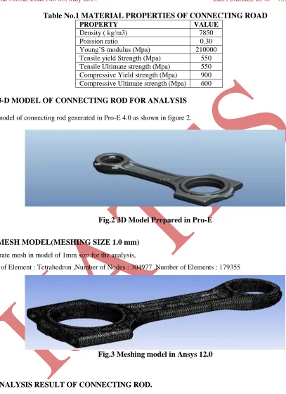
Table No.1 MATERIAL PROPERTIES OF CONNECTING ROAD
PROPERTY VALUE
Density ( kg/m3) 7850
Poission ratio 0.30
Young’S modulus (Mpa) 210000
Tensile yield Strength (Mpa) 550
Tensile Ultimate strength (Mpa) 550 Compressive Yield strength (Mpa) 900 Compressive Ultimate strength (Mpa) 600
III. 3-D MODEL OF CONNECTING ROD FOR ANALYSIS
The model of connecting rod generated in Pro-E 4.0 as shown in figure 2.Fig.2 3D Model Prepared in Pro-E
IV. MESH MODEL(MESHING SIZE 1.0 mm)
Generate mesh in model of 1mm size for the analysis,Type of Element : Tetrahedron ,Number of Nodes : 304977 ,Number of Elements : 179355
Fig.3 Meshing model in Ansys 12.0
V. ANALYSIS RESULT OF CONNECTING ROD.
341 |
P a g e
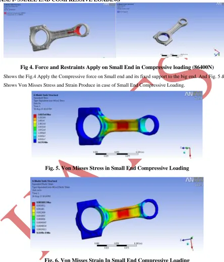
CASE I- SMALL END COMPRESSIVE LOADING
Fig 4. Force and Restraints Apply on Small End in Compressive loading (86400N)
Shows the Fig.4 Apply the Compressive force on Small end and its fixed support to the big end. And Fig. 5 &6 Shows Von Misses Stress and Strain Produce in case of Small End Compressive Loading.Fig. 5. Von Misses Stress in Small End Compressive Loading
Fig. 6. Von Misses Strain In Small End Compressive Loading
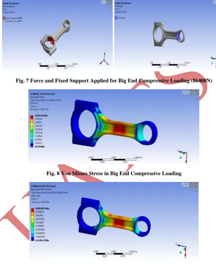
CASE II- BIG END COMPRESSIVE LOADING
342 |
P a g e
Fig. 7 Force and Fixed Support Applied for Big End Compressive Loading (86400N)
Fig. 8 Von Misses Stress in Big End Compressive Loading
Fig. 9 Von Misses Strain in Big End Compressive Loading
343 |
P a g e
Table No.-2 RESULTANT STRESS, STRAIN AND F.O.S
.VI. OPTIMIZATION
Aim of the optimization process is to minimize the material of the connecting rod under the effect of a load range (max. compression to max. tensile). Due to material reduction automatically production cost of the connecting rod was also to be minimized. Furthermore, the buckling load factor under the peak gas load has to be permissible. So this reason new design (modified or optimized) can be replace to existing design for lower value of weight and cost. This requires some of the dimensions in the existing connecting rod to be maintained.suraj pal et al (2012) [4] found from their experimental data that stress is found maximum at the piston end and design parameter of connecting rod with modification gives sufficient improvement (reducing weight of connecting rod 0.477 gm) in the existing results.The model after the optmization again cross check for stress and strain analysis to get F.O.S. value which is inrange of 1.6 to 1.9 that means its safe.
ANNA ULATOWSKA (2008) [5] has work on optimization topology on connecting rod. And he can conclude Results are scaled to 270 MPa in order to show how stresses are compensated after optimization and scaled to 300 MPa in order to show how maximum stresses are decreased after optimization. It is shown that before optimization it is a few point with stress concentration, but all model has moderate stress. After optimization it is clear (from their result of optimization) that stress is more uniform, which was the object of this studies.M.S. Shaari et al (2010) [6] prepared structural modeling, finite element analyze and the optimization of the connecting rod for robust design for weight and cost improvement. In this paper author use SOLIDWORKS software for Modeling of connecting rod and Finite element modeling and analysis were performed using MSC/PATRAN and MSC/NASTRAN software. Linear static analysis was carried out to obtain the stress/strain state results. From the FEA analysis results, TET10 predicted higher maximum stress than TET4 and maximum principal stress captured the maximum stress. The crank end is suggested to be redesign based on the topology optimization results. The optimized connecting rod is 11.5 % lighter and predicted low maximum stress compare to initial design. For future research they suggest that the weight reduction should cover on material suggestion.Here rim curvature at the big end side is totally free from the stress so it is a place where we can absorve excess material so we can remove a material over here.By optimization we can reduce a mass of connection rod up to 0.702 from 0.792 Kg(10% Reduction).
End Condition Load (N) Max. Stress (MPA) Max.
Strain F.O.S
SmallEnd
Compression 86400 359.19 1.7 1.67
BigEnd
344 |
P a g e
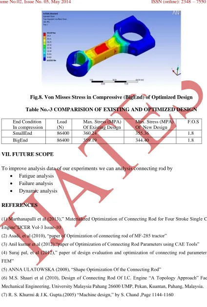
Fig.8. Von Misses Stress in Compressive (BigEnd) of Optimized Design
Table No.-3 COMPARISION OF EXISTING AND OPTIMIZED DESIGN
End ConditionIn compression
Load (N)
Max. Stress (MPA) Of Existing Design
Max. Stress (MPA) Of New Design
F.O.S
SmallEnd 86400 360.24 355.36 1.8
BigEnd 86400 359.19 344.40 1.8
VII. FUTURE SCOPE
To improve analysis data of our experiments we can analysis connecting rod by
Fatigue analysis
Failure analysis
Dynamic analysis
REFERENCES
(1) Marthanapalli et al (2013),” Materialized Optimization of Connecting Rod for Four Stroke Single Cylinder Engine”IJCER Vol-3 Issue-10
(2) Asadi, et al (2010), “paper of Optimization of connecting rod of MF-285 tractor”
(3) Anil kumar et al (2012) “paper of Optimization of Connecting Rod Parameters using CAE Tools”
(4) Suraj pal, et al (2012),” paper of design evaluation and optimization of connecting rod parameters using FEM”
(5) ANNA ULATOWSKA (2008), “Shape Optimization Of the Connecting Rod”
(6) M.S. Shaari et al (2010), Design of Connecting Rod Of I.C. Engine “A Topology Approach” Faculty of Mechanical Engineering, University Malaysia Pahang 26600 UMP, Pekan, Kuantan, Pahang, Malaysia.
![Fig -1: Automobile Connecting rod Marthanapalli et al (2013) [1] optimized and materialized a four stroke single cylinder 150cc engine connecting rod](https://thumb-us.123doks.com/thumbv2/123dok_us/9165240.1455108/2.612.72.539.148.559/automobile-connecting-marthanapalli-optimized-materialized-stroke-cylinder-connecting.webp)