© 2015 IJSRSET | Volume 1 | Issue 2 | Print ISSN : 2395-1990 | Online ISSN : 2394-4099 Themed Section: Engineering and Technology
Development and Implementation of a Solar-Powered Automated
Irrigation Control System for Maize Crop Grown in Loamy Soil.
Ibrahim A. G.*1, Mosadomi, T. J.2, Odekunle, M. O3
1, 2
Department of Physics, Federal University of Technology, Minna, Nigeria
3
Department of Geography, Federal University of Technology, Minna, Nigeria
ABSTRACT
This work presents a microcontroller based system which makes use of soil moisture sensors and plant growth models to develop irrigation schedules for maize crop grown in loamy soil. The methodology adopted for this work involves field survey, electronic circuit design, implementation and testing. The field studies provided details on the crops root depth pattern and water requirement throughout its growth period. With a dual power source of solar and a.c power supply, moisture sensor, microcontroller, LDR, LCD and sprinkler units; the microcontroller would permit the sprinkler to start and stop at given times during each growth period when the soil moisture falls below a predetermined level as sensed by the soil moisture sensors. Also included in this design is a DTMF decoder unit that permits interaction with the farmer on the current state and step to be initiated by the device via a remote phone. Test results indicate effective irrigation throughout the maize crop‟s life cycle, bringing about improved crop yield/quality, water and energy conservation.
Keywords: Irrigation, Loamy soil, Microcontroller, Maize crop, Soil sensor.
I.
INTRODUCTION
Modern agriculture require specialized knowledge, hence depends on engineering and technology, and on the physical sciences for maximum results. One of such specialized aspect is irrigation. Irrigation is the artificial application of water to the land to assist in the growing of agricultural crops [1]. Irrigation has an extreme advantage which is that it produces twice the yield of non irrigated fields although presents about 18 per cent of all land under cultivation [2]. However, it can waterlog soil or increase soil salinity to the plant such that the crops are damaged or destroyed if not managed properly [3] and [4]. A good irrigation system apart from supplying water to crops should also be water economical [5]. Water in most part of the world is scarce especially during the dry season [6], hence the need to maximise whether it is natural or artificial [1] and [7]. Since water requirements differ from crop to crop with this requirement varying with age (root depth) [8], it was the reason this device was made to be crop
and/quality, water and energy conservation, less manpower and low production costs.
II.
METHODS AND MATERIAL
The methodology adopted for this work is as follows: field survey, electronic circuit design, implementation and testing
2.1 Field survey
In a work of this nature, field experimentation is necessary for a correct simulation of realistic phenomenon [11] and [12]. In this case, a field study was carried out to match the maize crop‟s water demands with its growth period. Since the crop‟s water demand changes over time as the root zone increase over its growth cycle. A knowledge of the rate at which the root zone of the crop increases over time will serve as a guide for the irrigation scheduling throughout the plant‟s growth cycle. To do this, a critical assessment of the root growth pattern was done so as to ascertain the right quantity of water required at specific depth. In order to achieve this, some maize seeds were planted on separate rows on a loamy soil garden and specific quantity of water supplied at different growth periods using manual irrigation for each row. The usual cultural practices for maize were observed except that certain growth periods were under irrigated, moderately irrigated or over irrigated. This was done to assess the best quantity of irrigated water for every growth period. Evening times were chosen for irrigation due to the fact that the water will have enough time to percolate to desired root depth with little loss to evaporation [13]. The measurement of the degree of resistance offered by the moist soil was done with the aid of an ohmmeter and moisture sensors, while observing the root growth patterns, quantity of water supplied and the yield/quality of the crop over time. In order to know the root growth pattern of the crop, one pair was carefully uprooted per week and its root depth measured. Table 1 shows the result obtained for the root depth spanning through the growth stages of the maize crop.
Table 1: Root Depth of Maize Crop Corresponding to Growth Stages.
Growth Stages Period Root Depth Average (day) (cm) Depth(cm)
Establishment Period 15-25 5-7 6 Vegetative Period 40-65 8-10 9 Flowering Period 55-85 12-15 13.5 Yield formation Period 90-125 15-17 16 Ripening Period 100-150 17-18 17.5
Vital results from the field work and corroborated with existing knowledge has it that, water deficit during the flowering period result in reduction in grain number per cob [14], water deficits during the yield formation period leads to reduction in grain size [15], whereas, water deficit during the ripening period has little effect on grain yield. Maize appears relatively tolerant to water deficits during the vegetative and ripening periods. Water logging should be avoided, particularly during the flowering and yield formation periods as water logging during these periods can reduce grain yields by 50 percent or more. The row with the best yield along with its water scheduling was adopted for this work. The resistance values corresponding to the soil moisture condition when irrigation will be required was measured as 0.95 Ω while those for over irrigation, moderate irrigation and under irrigation are 0.2 Ω, 0.35 Ω and 0.5 Ω respectively.
2.2 Electronic Circuit Design
The result of the field studies alone side other previous information will now be electronically incorporated into the design to create a more effective, water economical and interactive irrigation control system. The sections of the design are explained below.
Power supply
LC D
Sensor Sprinkler
Micro-Controller
GSM
Phone
DTMF
Decoder Day/Night
Sensor
Figure 1: Block diagram of the irrigation control system
[18]. Therefore a dual power supply system comprising the solar power and the conventional power supply circuits were designed. The solar power section comprises of three constituents namely: the solar panel, solar charge controller and the battery. The enormous renewable energy of the sun was harnessed using an 18 V, 50 W monocrystalline solar panel positioned at the right tilted angle of 10o (latitude of location) due south for a maximum solar gain. From power analysis of the device, the power requirement of constituent sections is 25 W with the maximum voltage and current ratings of 10 V and 2.5 A. The resultant 18V, 50 W capacity solar panel was used to charge a 12 V, 7.5 A battery. The solar panel, battery and load (successive sections) was regulated by a 12 V, 10 A solar charge controller. While the conventional power supply section is made up of a 220 - 10 V step down transformer for stepping from mains, bridge rectifier for conversion to dc, a 50 V, 3300 µF capacitor (C1) for elimination of ripples and a 7805, 7809 and 7810 regulators to peg the output at 5 V, 9 V and 10 V respectively as will be required by subsequent sections. A socket was provided just before the regulator where either the solar or a.c power supply can be plugged in.
Signal flow through successive sections of a device is simplified using a block diagram [19]. The block diagram of the system is shown in figure 1.
Each section will be discussed one after the other.
The Sensor Unit
Sensors are incorporated into devices to detect specific characteristics of their environment [20]. In this work, the sensor unit has a responsibility of monitoring the level of soil moisture at the root zone of the crop. The sensor is sunk into the ground so that the contact points
could monitor the level of moisture in the soil. It works by the principle of electrical conductivity. When the moisture content is high, conductivity is high (water being a conductor of electricity) and resistance is low while for low moisture content, conductivity is low and resistance is high. Resistivity of a material ρ, quantifies how strongly the given material opposes the flow of electric current, while conductance σ, measures a material's ability to conduct an electric current. Both quantities are related as shown in equation (1).
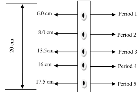
σ = 1/ρ (1) where σ is the conductivity of the soil and ρ is the resistivity of the soil [21]. When water falls below the predetermined minimum level, the sensor senses a high resistance and instructs the microcontroller (a successive section) to take action by sprinkling water of specific quantity. The calibration of the sensor is dependent on the rooting characteristic of the crop and for this reason; the field survey above was conducted for an assessment of the changes in the root (soil) zone and water demand over the life cycle of the crop. A resistance of 0.95 Ω corresponds to the moist condition of the soil when irrigation will be required. Result of the field survey displayed in Table 1 was used to calibrate the sensor. The kind of sensor used in this design is a 20 cm long wooden bar, having metallic thumb tacks fixed at some determined points in it to serve as the contact points. With reference to table 1, the period 1 to period 5 of the plant‟s growth process corresponds to the average root depths of 6, 8, 13.5, 16 and 17.5 cm respectively, so metallic thumb tags were inserted at these intervals and sunk into the ground to help ascertain the moisture condition of the crop per time and throughout the season. Figure 2 is a schematic diagram of the sensor.
.
Figure 2: Calibration of Sensor
2
0
c
m
Period 2 Period 1
Period 3 6.0 cm
8.0 cm
13.5cm
17.5 cm
16.cm Period 4
At the maturity stage, water has little or no effect on the crop, therefore period 4 and 5 were merged together. Each of the metallic thumb tag for period 1 to 4 of the sensor SW1 were directly connected to pin 1, 2, 3, 4 of the microcontroller. LED‟s D2 to D5 were incorporated and are to turn ON at same growth period that sensor 1 to 4 are respectively to monitor. The second sensor (SW2) is connected to pin 11, 12, 13 and 26 of the microcontroller respectively. The microcontroller via its programmed instruction, triggers each sensor to function when its growth period is due while the sensors also feeds the microcontroller of the moist condition around the root zone. If below the predetermined value of 0.95 Ω, water is sprinkled until the resistance of the soil drops to the predetermined value for the current growth period before the microcontroller takes appropriate action by tripping OFF the sprinkler unit.
The Microcontroller Unit
The microcontroller is an embedded system in a chip which executes instructions based on the programme written on it. This is the „brain‟ of the system as it controls and processes input signals, giving the appropriate output signals to the interconnected units. In this work, the microcontroller used is the AT89C52
from 8051 family. The microcontroller was
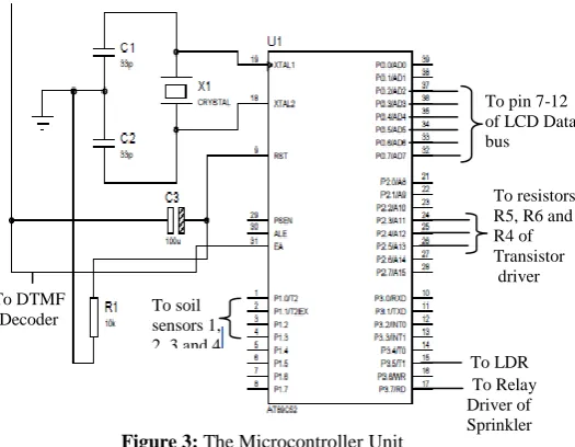
programmed using assembly language through a hard ware called top win universal programmer. Pin 40 serves as the Vcc, and powered by a 5 V regulator from the power unit. The controller uses a 12 MHz crystal oscillator as its operating frequency. This is based on the delay frequency needed for this design. With a 12 MHz crystal, the microcontroller unit is capable of executing one million instructions per second [22]. The AT89C52 microcontroller factory connection as implemented in this design is shown in figure 3.
The microcontroller exercises electronic control over other sections it communicates with through its pin connection to such sections. With the connection of figure 3, the microcontroller carries out the following functions:
1 Runs the embedded software code that controls the system.
2 Triggers and monitors the state of the sensor. 3 Sends and receives signal from the GSM phone
through the DTMF decoder. 4 Receives signal also from the LDR.
5 Sends signal to the sprinkler on when to sprinkle and when to stop.
6 Sends signal to the LCD for display of the operation being performed or intended at a particular time.
The Dual Tone Multi-Frequency (DTMF) Decoder
The DTMF is a Dual Tone Multi-Frequency receivern which is capable of decoding a 16 bit code from a GSM phone and converting it to a 4 bit corresponding binary code, and then latches it on its output pins. It serves as the communication link between the microcontroller and a remote GSM phone to be in possession of the farmer. A quartz crystal oscillator of 3.592 MHz is connected at its pin 7 and 8 to provide its operating frequency. A 5 V source from the power supply unit is connected to pin 18 of the decoder, and the pin 9 to the ground. Pin 1 and 2 serve as its input. Pin 11, 12, 13 and 14 of the decoder are its output and are connected to port1 bit 0, port1 bit 1, port1 bit 2 and port1 bit 3 respectively. Pin 15 serves as the signal indicator; this pin only goes high whenever the DTMF decoder
Figure 3: The Microcontroller Unit
To resistors R5, R6 and R4 of Transistor driver
To LDR To DTMF
Decoder
To pin 7-12 of LCD Data bus
To Relay Driver of Sprinkler To soil
registers a valid tune received from a remote GSM phone. It then latches it‟s output on the microcontroller‟s pin 10 and 31 for onward action. The point of connection is shown in the general circuit diagram of figure 8.
The Global System for Mobile Communications (GSM) Module
The GSM phone serves as the remote phone to the DTMF receiver. The phone is set on auto answer so as to automatically receive any incoming call relayed from the DTMF module. The remote phone would be expected to key-in the required code for the microcontroller to perform a certain tasks to operate the sprinkler. The phone shall receive a message “about to sprinkle” from the microcontroller through the DTMF. The farmer has a choice of replying “OK” to commence sprinkling immediately or ignore the message and postpone sprinkling for another thirty minutes. This period is to allow the farmer ample time to return to the farm and supervise the sprinkling process when necessary. Once the remote phone is through with the
operation, the operator can hang up. The
microcontroller also interacts with the remote GSM phone on the state of the soil moisture sensors.
To configure the GSM phone to undertake this task, it needs to be driven. For this reason, a pnp transistor (BC557) is connected to the „select‟ button of the phone to automatically perform this required operation; one lead of the transistor to the negative point and the other lead to the positive point. Then the transistor is connected through a 1.5 kΩ resistor to port 2 bit 4 (pin 24) of microcontroller chip. The same connection is done with two other transistors to the „down‟ button and the „back‟ button of the receiver phone, and then to the port 2 bit 6 (pin 25) and port 2 bit 5 (pin 26) of the microcontroller respectively. The emitter of the transistors were tied together and connected to the positive points while the collectors were connected to the negatives of appropriate buttons. Figure 4 shows how the phone transistor drivers were connected to the GSM phone.
R4
1.5K
R5
1.5K
R6
1.5K
Q1
BC557
Q2
BC557
Q3
BC557
D7
DIODE
D8
DIODE
D9
DIODE
phone driver transistors
The Light Dependent Resistor (LDR) Unit
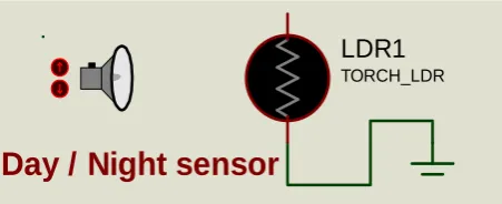
The LDR is connected to the microcontroller port 3 bit 4 (pin 15), and the other pin is tied to the ground. In the day time, port 3 bit 4 is pulled low because the internal resistance of the LDR is low (about 200 Ω) therefore, the controller is aware that its day. In the evening when, the LDR‟s resistance rises to about 2 MΩ, this sends a pulse to the microcontroller through port 3 bit 4 that its evening and the controller acts appropriately. The controller on sensing evening
Figure 5: The Light Dependent Resistor.
triggers the sprinkler to come up. In order to achieve this, the photo limit was earlier adjusted by varying the variable resistor to the 2 MΩ value. Figure 5 shows the Light Dependent Resistor.
The Sprinkler Section
This section comprises of the motor pump, relay and it‟s driver unit. They become active only when the LDR senses evening and sends a pulse to the microcontroller which in response turns ON the sprinkler section. The sprinkler is powered via the relay (RL1) to serve as control switch. As soon as the relay toggles, the motor
Figure 4: Phone Transistors Driver
LDR1
TORCH_LDR
pumps out water for sprinkling of the soil around the root zone until its moisture content reaches the desired level as sensed by the soil moisture sensor which sends feedback to the microcontroller. A 10 V pump was used with an attached horst connecting from the water tank to the crop‟s base. The sprinklers relay is driven by a BC 557 pnp transistor having a limiting base resistance of 1 kΩ (R7). The base of the transistor is connected to pin 17 of the microcontroller from where the section is triggered. The circuit diagram of the sprinkler section is shown in figure 6.
RL1 12V Q4 BC557 +88.8 kRPM sprinkler Q4 BC557 R7 1k
Figure 6: The Sprinkler Section.
The Liquid Crystal Display (LCD) Unit
The LCD used is a 74HD green phase 16 x 2 type, meaning it can only display a maximum of 32 characters in two lines, with 16 in each line. The LCD data port is connected to port 0 of the microcontroller in the following way: The LCD data/bus line (pin 7-14) is connected to microcontrollers pin 32-39 respectively. While the control pins (pin 4-6) is connected to microcontrollers pin 21-23 respectively. LCD pin 1 and pin 2 are its power supply (to VCC), pin 3 is the contrast
variable resistor (RV1) for setting the brightness of the characters displayed to one‟s desire. Figure 7 shows the LCD connection.
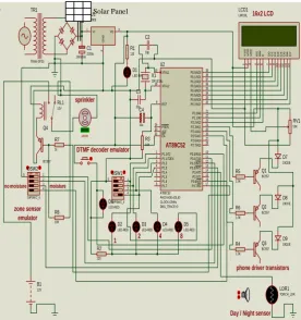
The display on the LCD include: “Hello”, “Irrigation Control System”, “Running period 1”, “Running period 2”, “Running period 3”, “Running period 4”, “about to sprinkle”, “Sprinkling in progress”, soil moisture content: High”, soil moisture content: Low” and so on. The overall circuit diagram of the solar powered automated irrigation control system for maize crop grown in loamy soil is shown in figure 8.
TR1
TRAN-2P2S
BR1
2W005G VI 1 VO 3
G N D 2 U1 7805 C1 2200u D1 LED-BIRY R1 120 XTAL2 18 XTAL1 19 ALE 30 EA 31 PSEN 29 RST 9 P0.0/AD0 39 P0.1/AD1 38 P0.2/AD2 37 P0.3/AD3 36 P0.4/AD4 35 P0.5/AD5 34 P0.6/AD6 33 P0.7/AD7 32 P1.0/T2 1 P1.1/T2EX 2 P1.2 3 P1.3 4 P1.4 5 P1.5 6 P1.6 7 P1.7 8 P3.0/RXD 10 P3.1/TXD 11 P3.2/INT0 12 P3.3/INT1 13 P3.4/T0 14 P3.7/RD 17 P3.6/WR 16 P3.5/T1 15 P2.7/A15 28 P2.0/A8 21 P2.1/A9 22 P2.2/A10 23 P2.3/A11 24 P2.4/A12 25 P2.5/A13 26 P2.6/A14 27 U2 AT89C52 PACKAGE=DIL40 CLOCK=2MHz DBG_TRACE=0 D 7 1 4 D 6 1 3 D 5 1 2 D 4 1 1 D 3 1 0 D 2 9 D 1 8 D 0 7 E 6 R W 5 R S 4 V S S 1 V D D 2 V E E 3 LCD1 LM016L D2 LED-RED D3 LED-RED D4 LED-RED D5 LED-RED D6 LED-RED R2 220 R3 10K R4 1.5K R5 1.5K R6 1.5K RV1 50K Q1 BC557 Q2 BC557 Q3 BC557 X1 CRYSTAL C2 33p C3 33p C4 10u
OFFON 1 2 3 4 5 DSW1 DIPSWC_4
OFFON 1
2 3 4 5 DSW2 DIPSWC_4
1 2 4 8
LDR1
TORCH_LDR
Day / Night sensor D7 DIODE D8 DIODE D9 DIODE RL1 12V Q4 BC557 R7 1k +88.8 kRPM sprinkler
DTMF decoder emulator
16x2 LCD
phone driver transistors AT89C52
R8
10K
zone sensor emulator
no moisture moisture
B1
12V
Figure 8: Overall Circuit Diagram of the Device
2.3 Implementation
The electronic components and parts of the design in figure 8 were carefully arrived at through design calculations or standard functions. They were electronically assembled in line with circuit schematics and cased. The LDR was separately cased in a transparent box to control the illumination around it. The solar panel was raised to a height of 4.0 m above the ground and tilted to 10o due south with the aid of a metal rod for maximum solar exposure. The solar panel also serves as shelter for the casing which is attached just below the solar panel. A plastic pipe connects from the water tank located at the base to the sprinkler‟s pump through the inlet and another pipe which is underground connects from the outlet to the soil surface, close to the crop‟s root zone. The wiring from the soil Figure 7: The Liquid CrystalDisplay
Unit.
To pin 32-39 of
Microcontroll er
VCC
RV1
To pin 21-23 of
Microcontroll er
moisture sensors to the microcontroller were neatly packaged to follow along the outlet pipe back to the casing where they are plugged into external sockets. This prototype was implemented with two sensors, two outlet pipes and connected to two maize crops. In field setting, same arrangement is maintained but the outlet pipes are duplicated around the farm, maintaining same distance to the crop. Since mono cropping (only maize) is practiced with all the crops planted same day, at equal depth, equal spacing and same soil type (loamy soil); the moisture condition of their root zone will be the same. Therefore only two maize crops were used as samples and to which the soil moisture sensors were connected to their root zones for an assessment of moisture condition at other root zones.
III.
RESULTS AND DISCUSSION
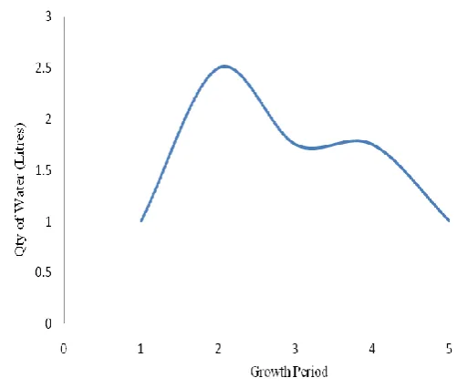
On the field assessment shows that times of LCD display of soil moisture content: “High”, and soil moisture content: “Low” correspond to periods when the soil at the root zone are getting a little dried and when the soil is moist enough respectively. Also is the LDR section which constantly turns ON the sprinkler‟s pump at about 4.00 to 5.00 pm in the evenings. Also striking is the level of interaction between the system and the remote phone. The farmer is kept abreast on happenings at the root zone, current growth period and notification of intention to sprinkle. The reply which delays or instantly initiates the sprinkling process was tested at evenings by sending a short code “OK” which witnessed instant sprinkling and ignoring the message which witnessed a delay of thirty minutes before sprinkling. The quantity of water sprinkled per round and per stand for each growth period were separately collected and measured. The graph of figure 9 shows the variation in the quantity of water sprinkled for each growth period.
Figure 9: Water Irrigation Curve for Maize
From the nature of the curve in figure 9, it can be seen that the water used up per stand during irrigation by selecting a round each from each growth period in a season goes from a low for period 1 (establishment period) to a high for period 2 (vegetative period), to a moderate for period 3 (flowering period) and period 4 (yield formation period) and back to a low at period 5 (ripening period). This is against other conventional types of irrigation with a constant graph and requiring even application of water or is based on the discretion of the farmer. Such a type waste water, requires manpower and prone to water logging and water percolation.
IV.
CONCLUSION
The improvement of the system to become multi-crop and multi-soil type by upgrading the microcontroller and its software such that a crop of interest and a soil type can be selected and an effective irrigation management system is ran throughout the crop‟s life cycle.
Development of a robust underground water outlet pipes that will deliver the required quantity of water needed for each growth period directly at a depth closest to the root hairs. This will further save water loses associated with peculation of water from soil top to desired root depth.
V.
REFERENCES
[1] J. C. Rodda, and L. Ubertini, The Basis of Civilization – Water Science? International Association of Hydrological Sciences (International Association of Hydrological Sciences Press. pp 161, 2004.
[2] L.K. William, I. Suat, J. Simon, C.D. Yonts and L.M. Derrel,Irrigation Management for Corn. Retrieved on 9th
March, 2014 from
www.ianrpubs.unl.edu/pages/publicationD.jsp?publicatio nId=1004
[3] Civil Engineers Forum. Retrieved on 23th November, 2014 from www.civilengineersforum.com/irrigation-advantages-disadvantages/)
[4] J. Needham, Science and Civilization in China: Volume 4, Physics and Physical Technology, Part 2, Mechanical Engineering. Taipei: Caves Books Ltd, pp. 344-346, 1986.
[5] Water Issue Brief. Wastewater use in agriculture: Not only an issue where water is scarce! International Water Management Institute, 2010.
[6] S.V. Zonn, Tropical and Subtropical soil science 2nd Edition. Mir publishers, 2 Pervy Rizhsky pereulok I-110, GSP, Moscow, 129820 USSR. pp. 67, 1986.
[7] F.A.O, Retrieved on 19th March, 2014 from http://www.fao.org/docrep/w4347e/w4347e0c.htm [8] P. Bandiyopadhyay, Effect of soil moisture levels on root
distribution, water uptake and crop coefficient of winter maize in a humid tropic region. Retrieved on 20 April,
2003 from
www.academia.edu./Effect_of_soil_moisture_levels_on_ root_distribution_water_uptake_and_crop_coefficient_of _winter_ maize_ in_a_humid-tropical region.
[9] G.W. Leeper and N.C. Uren, Soil Science: An Introduction, 5th edn. Melbourne University Press, Melbourne. pp. 25, 1993.
[10] D. Raes, P. Steduto, T.C. Hsiao and E. Fereres, AquaCrop--The FAO Crop Model to Simulate Yield
Response to Water: II. Main Algorithms and Software Description. Agronomy Journal. pp. 101, 438-447, 2009. [11] P. Steduto, T. Hsiao, D. Raes and E. Fereres,
AquaCrop--The FAO Crop Model to Simulate Yield Response to Water: I. Concepts and Underlying Principles. Agronomy Journal. pp. 426-437, 2009.
[12] www.clemson.edu/extension/hgic/plants/other/irrigation/ hgic1804.html.
[13] O.B. Dennis, Manual for Maize Production. Bunso cocoa college. 2011. Retrieved on 10/3/2015 from www.slideshare.net/DENNIS90/manual-for-maize-production-9558330.
[14] T. Phil, Growth stage guidelines: Early-season corn irrigation needs. Delta Farm Press. pp. 20-25, 2003. [15] B. Grob and E.S. Mitchel, Basic Electronics. (9th ed.).
Columbus: Glencoe/McGraw-Hill, pp.1,5, 2003.
[16] A. G. Ibrahim, O.D. Oyedum, O.B. Awojoyogbe and S.S.N. Okeke, Developmental features and implementation challenges of electronic pest control devices in developing countries. International Journal of Scientific and Engineering Research, 5(2), 411- 416, 2014.
[17] A.G. Ibrahim, Development and Performance Evaluation of a Solar-Powered Ultrasonic Device for the Control of Weaver Birds in Farms. A Ph.D thesis, Physics departmemt, Federal University of Technology, Minna, Nigeria. pp.103-107, 2015.
[18] C.A. Shuler, Electronic Principle and Application. Glencoel McGraw Hill Columbus. pp 7, 1984.
[19] M. Kretschmar and S. Welsby, Capacitive and Inductive Displacement Sensors in Sensor Technology Handbook, J. Wilson editor, Newnes: Burlington, MA. pp. 77-84, 2005,
[20] P.M. Levy and Z. Shufeng, Electrical Conductivity of Magnetic Multilayered Structures." Physical Review Letters 65.13 1643-646, 1990.
![(1 Butyl 1,4 diazabicyclo[2 2 2]octon 1 ium κN4)trichloridocobalt(II)](data:image/gif;base64,R0lGODlhAQABAIAAAP///wAAACH5BAEAAAAALAAAAAABAAEAAAICRAEAOw==)