261 | P a g e
AN INTEGRATION OF WIND – PV GENERATOR WITH
ENERGY STORAGE SYSTEMS
Ganesh Varma. R
1, Krishna Mohan T
21
Assistant Professor, Dept. of EEE, Amritha Sai Institute of Science & Technology, VJA (India)
2
Assistant Professor, Dept. of EEE, Andhra Loyola Institute of Engg. & Tech, VJA (India)
ABSTRACT
Environmentally friendly solutions are becoming moreprominent than ever as a result of concern regarding the state
of ourdeteriorating planet. This paper presents a new system configurationof the front end rectifier stage for a
hybrid wind/photovoltaic energysystem. This configuration allows the two sources to supply theload separately or
simultaneously depending on the availability ofthe energy sources. There is no need for additional input filters to
eliminate the high frequency harmonics, because the PV cell is operated by the new converter. The fused
multiinputrectifier stage also allows Maximum Power Point Tracking(MPPT) to be used to extract maximum power
from the wind andsun when it is available. An adaptive MPPT algorithm will be usedfor the wind system and a
standard perturb and observe method willbe used for the PV system. Operational analysis of the proposedsystem
will be discussed in this paper. Simulation results are givento highlight the merits of the proposed circuit.
I. INTRODUCTION
Renewable energy technologies offer the promise to clean, abundant energy gathered from self – renewing resources such as sun, wind, water, earth and plants. Virtually all regions of the world have renewable resources of one type or another. Renewable energy technologies offer important benefits compared to those of conventional energy sources. Worldwide, 1000 times more energy reaches the surface of the earth from the sun than is released today by all fossil fuels consumed. PV and wind generation are also an attractive source of energy because of their benign effect on the environment.When a source is unavailable or insufficient in meeting theload demands, the other energy source can compensate for thedifference. Several hybrid wind/PV power systems withMPPT control have been proposed and discussed in works [1]-[5]. Most of the systems in literature use a separate DC/DCboost converter connected in parallel in the rectifier stage asshown in Figure 1 to perform the MPPT control for each ofthe renewable energy power sources [1]-[4]. A simpler multiinputstructure has been suggested by [5] that combine thesources from the DC-end while still achieving MPPT for eachrenewable source. The structure proposed by [5] is a fusion ofthe buck and buck-boost converter.
262 | P a g e
realized for eachsource; 4) individual and simultaneous operation is supported.The circuit operating principles will be discussed in this paper.Simulation results are provided to verify with the feasibility ofthe proposed system.
Fig 1: Hybrid system with multi-connected boost converter
II. PROPOSED MULTI-INPUT RECTIFIER STAGE
A system diagram of the proposed rectifier stage of ahybrid energy system is shown in Figure 2, where one of theinputs is connected to the output of the PV array and the otherinput connected to the output of a generator. The fusion of thetwo converters is achieved by reconfiguring the two existingdiodes from each converter and the shared utilization of theCuk output inductor by the converter. Thisconfiguration allows each converter to operate normallyindividually in the event that one source is unavailable. Figure3 illustrates the case when only the wind source is available.In this case, D1 turns off and D2 turns on; the proposed circuitbecomes a CUK converter and the input to output voltagerelationship is given by (1). On the other hand, if only the PVsource is available, then D2 turns off and D1 will always be onand the circuit becomes a Cuk converter as shown in Figure 4.The input to output voltage relationship is given by (2). Inboth cases, both converters have step-up/down capability,which provide more design flexibility in the system if dutyratio control is utilized to perform MPPT control.
263 | P a g e
III. ANALYSIS OF PROPOSED CIRCUIT
To find an expression for the output DC bus voltage, Vdc, the volt-balance of the output inductor, L2, is examinedaccording to Figure 6 with d2 >d1. Since the net change in thevoltage of L2 is zero, applying volt-balance to L2 results in (3).The expression that relates the average output DC voltage(Vdc) to the capacitor voltages (vc1 and vc2) is then obtained asshown in (4), where vc1 and vc2 can then be obtained byapplying volt-balance to L1 and L3
[9]. The final expressionthat relates the average output voltage and the two inputsources (VW and VPV) is then given by (5). It is observed thatVdcis simply the sum of the two output voltages of the Cukand SEPIC converter. This further implies that Vdccan becontrolled by d1 and d2 individually or simultaneously.
264 | P a g e
IV. MPPT CONTROL OF PROPOSED CIRCUIT
A common inherent drawback of wind and PV systems isthe intermittent nature of their energy sources. Wind energyis capable of supplying large amounts of power but itspresence is highly unpredictable as it can be here one momentand gone in another. Solar energy is present throughout theday, but the solar irradiation levels vary due to sun intensityand unpredictable shadows cast by clouds, birds, trees, etc.These drawbacks tend to make these renewable systemsinefficient. However, by incorporating maximum power pointtracking (MPPT) algorithms, the systems’ power transferefficiency can be improved significantly.To describe a wind turbine’s power characteristic, equation describes the mechanical power that is generated by thewind [6].
The power coefficient (Cp) is a nonlinear function thatrepresents the efficiency of the wind turbine to convert windenergy into mechanical energy. It is dependent on twovariables, the tip speed ratio (TSR) and the pitch angle. TheTSR, λ, refers to a ratio of the turbine angular speed over thewind speed. The mathematical representation of the TSR isgiven by equation [10]. The pitch angle, β, refers to the angle inwhich the turbine blades are aligned with respect to itslongitudinal axis.
Figure 3 are illustrations of a power coefficient curveand power curve for a typical fixed pitch (β =0) horizontalaxis wind turbine. It can be seen from figure 3 that thepower curves for each wind speed has a shape similar to thatof the power coefficient curve. Because the TSR is a ratiobetween the turbine rotational speed and the wind speed, itfollows that each wind speed would have a differentcorresponding optimal rotational speed that gives the optimalTSR. For each turbine there is an optimal TSR value thatcorresponds to a maximum value of the power coefficient(Cp,max) and therefore the maximum power. Therefore bycontrolling rotational speed, (by means of adjusting theelectrical loading of the turbine generator) maximum powercan be obtained for different wind speeds.
265 | P a g e
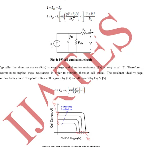
A solar cell is comprised of a P-N junction semiconductorthat produces currents via the photovoltaic effect. PV arraysare constructed by placing numerous solar cells connected inseries and in parallel [5]. A PV cell is a diode of a large-areaforward bias with a photovoltage and the equivalent circuit is shown by Figure 4 [11]. The current-voltage characteristic ofa solar cell is derived in [12] and [13] as follows:
Fig 4: PV cell equivalent circuit
Typically, the shunt resistance (Rsh) is very large and theseries resistance (Rs) is very small [5]. Therefore, it iscommon to neglect these resistances in order to simplify thesolar cell model. The resultant ideal voltage-currentcharacteristic of a photovoltaic cell is given by (17) and illustrated by Fig 5. [5]
Fig 5: PV cell voltage-current characteristic
266 | P a g e
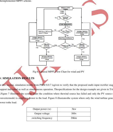
change in the outputpower, then the control algorithm will continue in thedirection of the previous perturbation. Conversely, if anegative change in the output power is observed, then thecontrol algorithm will reverse the direction of the perviousperturbation step. In the case that the change in power isclose to zero (within a specified range) then the algorithmwill invoke no changes to the system operating point since itcorresponds to the maximum power point (the peak of thepower curves).
The MPPT scheme employed in this paper is a version of theHCS strategy. Figure 6 is the flow chart that illustrates theimplemented MPPT scheme.
Fig 6: General MPPT Flow Chart for wind and PV
V. SIMULATION RESULTS
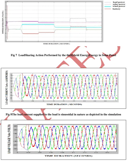
In this section, simulation results from PSIM 8.0.7 isgiven to verify that the proposed multi-input rectifier stagecan support individual as well as simultaneous operation. Thespecifications for the design example are given in TABLE I.Figure 7 illustrates the system under the condition where thewind source has failed and only the PV source (Cuk convertermode) is supplying power to the load. Figure 8 illustratesthe system where only the wind turbine generates power tothe load.
Output power (w) 3kw
Output voltage 500v
267 | P a g e
Fig 7 LoadSharing Action Performed by the theHybrid EnergyEnergy in Solar PanelFig 8The load current supplied to the load is sinusoidal in nature as depicted in the simulation
268 | P a g e
VI. CONCLUSION
In the thesis load demand is met from the combination of PV array, wind turbine and the battery. An inverter is used to convert output from solar & wind systems into AC power output.Circuit Breaker is used to connect an additional load of 5 KW in the given time. This hybrid system is controlled to give maximum output power under all operating conditions to meet the load.Either wind or solar system is supported by the battery to meet the load. Also, simultaneous operation of wind and solar system is supported by battery for the same load.
REFERENCES
[1] Joanne Hui*, AlirezaBakhshai, and Praveen K. Jain, “A Hybrid Wind-Solar Energy System: A New Rectifier Stage Topology “, in Applied Power Electronics Conference and Exposition (APEC), 2010 Twenty-Fifth Annual IEEE, pp 156-161, 21-25 Feb. 2010
[2] S.K. Kim, J.H Jeon, C.H. Cho, J.B. Ahn, and S.H. Kwon, “Dynamic Modeling and Control of a Grid-Connected Hybrid Generation System with Versatile Power Transfer,” IEEE Transactions on Industrial Electronics, vol. 55, pp. 1677-1688, April 2008.
[3] N. A. Ahmed, M. Miyatake, and A. K. Al-Othman, “Power fluctuations suppression of stand-alone hybrid generation combining solar photovoltaic/wind turbine and fuel cell systems,” in Proc. Of Energy Conversion and Management, Vol. 49, pp. 2711-2719, October 2008.
[4] Wind and Solar Power Systems Design Analysis and Operation Second Edition, by Mukund R. Patel, Taylor & Francis Group Publishing Co.
[5] Y.M. Chen, Y.C. Liu, S.C. Hung, and C.S. Cheng, “Multi-Input Inverter for Grid-Connected Hybrid PV/Wind Power System,” IEEE Transactions on Power Electronics, vol. 22, May 2007.
[6] S. Jain, and V. Agarwal, “An Integrated Hybrid Power Supply for Distributed Generation Applications Fed by Nonconventional Energy Sources,” IEEE Transactions on Energy Conversion, vol. 23, June 2008. [7] D. Das, R. Esmaili, L. Xu, D. Nichols, “An Optimal Design of a Grid Connected Hybrid
Wind/Photovoltaic/Fuel Cell System for Distributed Energy Production,” in Proc. IEEE Industrial Electronics Conference, pp. 2499-2504, Nov. 2005.
[8] Dos Reis, F.S., Tan, K. and Islam, S., “Using PFC for harmonic mitigation in wind turbine energy conversion systems” in Proc. of the IECON 2004 Conference, pp. 3100- 3105, Nov. 2004
[9] R. W. Erickson, “Some Topologies of High Quality Rectifiers” in the Proc. of the First International Conference on Energy, Power, and Motion Control, May 1997.