R E S E A R C H
Open Access
Throughput analysis of transmit-nulling SDMA
with limited feedback
Cheol Mun
1and Han-Shin Jo
2*Abstract
We recently proposed a precoder codebook for a transmit-nulling space-division multiple access (TN-SDMA) to share spectrum with existing wireless services. Since a portion of the spatial subspaces of a multiantenna broadcast channel is used to eliminate the interference to coexisting systems, TN-SDMA could benefit the efficiency of spectrum usage from the coexistence of different systems in the same band while it always yields lower throughput per unit bandwidth than the orthogonal SDMA (called per user unitary and rate control (PU2RC)) that utilizes all the spatial subspaces for data transmission. This study aims to theoretically quantify the throughput loss of TN-SDMA relative to PU2RC and to analyze the effect of the main system parameters (signal-to-noise ratio (SNR) and the numbers of transmit antennas, users, and feedback bits) on the throughput loss. We derive the theoretical upper bound of the throughput loss of TN-SDMA relative to PU2RC, with the same feedback bits (codebook size). The throughput loss is lower with more transmit antennas, fewer users, lower SNR, or fewer feedback bits. It is interesting to note that the throughput loss converges to an upper limit with an increase in the SNR, which indicates that the SNR has a comparatively minor effect on the throughput loss in the high-SNR region. We also derive the required additional number of feedback bits for TN-SDMA to achieve the throughput of PU2RC (i.e., zero throughput loss). We find that the throughput achieved is feasible at the cost of a practically small number of additional feedback bits.
1 Introduction
The economical use (or reuse) of the radio spectrum is increasingly essential as the number of radio spectrum shortages has risen because of an explosive growth in traffic [1]. In the background, high spectral efficiency (in bps/Hz) and smart spectrum sharing are becoming the key requirements of emerging (or future) wireless networks such as cognitive radio networks, femtocell networks, small cell networks, and International Mobile Telecommunications (IMT)-Advanced networks [2-5]. The use of multiple antennas in wireless networks has been of worldwide interest, and the resulting innovative techniques such as beamforming, single-user multiple-input multiple-output (MIMO), and multiuser MIMO (also named space-division multiple access (SDMA)) have been developed. Null-steering beamforming is prevalent for interference suppression in wireless communication and radar applications. An interest in SDMA is increasing
*Correspondence: [email protected]
2Department of Electronics and Control Engineering, Hanbat National University, Daejeon 305-719, South Korea
Full list of author information is available at the end of the article
because of its advantages over single-user MIMO [6], and furthermore, SDMA is considered as a high-data-rate solution for 3GPP Long-Term Evolution (LTE) and 3GPP LTE-Advanced [7]. Therefore, this paper focuses on SDMA that shares the spectrum with other coexisting systems.
1.1 Multiple antennas for spectrum sharing and SDMA
Spectrum sharing is possible by the sufficient separation of radio resource dimensions in time, frequency, and space; for example, a wireless communication system adjusts system resources such as the transmit power [8,9], operating frequency [10], and time of transmission [11]. Furthermore, by not radiating the interference in a known direction of the coexisting systems, null steering can protect coexisting systems without additional radio resources in time or frequency [12,13]. However, when a base station performs null steering without any use of multiple-antenna techniques for higher throughput, no downlink throughput gain caused by the usage of mul-tiple antennas is observed owing to their focusing on mitigating interference toward the coexisting system.
Dirty paper coding (DPC) is non-causal and thus impractical, although it achieves the MIMO broadcast channel capacity [14]. This clear finding has inspired the engineers in the field of wireless communications to develop numerous practical algorithms for SDMA [15-20]. In the industry, a codebook-based orthogonal beamforming SDMA has been proposed for the 3GPP-LTE standard [19] under the name per-user unitary rate control (PU2RC) and has been included in the 3GPP2-Ultra Mobile Broadband (UMB) standard [20]. In this scheme, on the basis of limited feedback information on the preferred precoding matrix within a codebook and the corresponding signal-to-interference-and-noise ratios (SINRs), a multiuser precoding matrix is selected within a codebook to maximize the sum throughput. In [21], the performance of PU2RC is intensively analyzed and com-pared with that of zero-forcing SDMA. The orthogonal beamforming of PU2RC focuses on throughput
improve-ment by reducing the inter-user interference in a homoge-neous system. However, the SDMA systems that share the spectrum with other wireless systems require suppression of the interference between heterogeneous systems as well as the inter-user interference in a homogeneous system.
As introduced above, employing multiple antennas is desirable for both spectrum sharing and through-put improvement. A multiple-antenna technology that simultaneously accomplishes null-steering and orthogo-nal beamforming could achieve both a high data rate and spectrum sharing. More specifically, it could be consid-ered that a part of orthogonal spatial subspaces provided by multiple antennas is dedicated to spectrum sharing, and the remainder (i.e., the corresponding null space) is allocated for data transmission. In [22,23], we realized this concept explicitly by designing a transmit-nulling SDMA (TN-SDMA) codebook satisfying both null-steering and orthogonality constraints, where each precoding matrix comprises mutually N−1 (N denotes the number of transmit antennas) orthonormal vectors that are orthog-onal to the array steering vector in the direction of a coexisting system. The codebook design proposed in [22,23] ensures low complexity and small over-head as compared with the well-known Gram-Schmidt process.
1.2 Contributions
In [22], simulation results show that the throughputa of TN-SDMA is always lower than that of PU2RC, with the same feedback bits, which is natural because not all of the orthogonal spatial subspaces of a broadcast channel are used for simultaneous data transmission in TN-SDMAb. However, it is still of importance to theo-retically quantify (1) how large the throughput loss of TN-SDMA is relative to PU2RC; (2) how the throughput loss is affected by the signal-to-noise ratio (SNR) and
the numbers of antennas, users, and feedback bits; and (3) how many additional feedback bits are necessary for TN-SDMA to achieve the PU2RC throughput, i.e.,
zero throughput loss, all of which are addressed in this paper.
We derive the throughput loss of TN-SDMA relative to PU2RC, with the same number of feedback bits in Theorems 1 and 2. TN-SDMA uses a codebook com-prising multiple sets of orthonormal vectors and PU2RC scheduling with limited feedback. In this sense, our anal-ysis is in the same spirit as the work of [21]. How-ever, we deterministically generate the precoding matrices with a systematic rule, whereas [21] randomly generates the matrices. This results in different statistics for the channel-shape quantization error from [21] as well as ran-dom vector quantization [24,25]. Additionally, we adopt a precoding matrix comprisingN−1 mutually orthonormal column vectors in CN for a transmitter with N
anten-nas, thereby having a different received SINR from that in [21].
In Theorem 3, we further derive the required num-ber of feedback bits for TN-SDMA to achieve the throughput of PU2RC, for a given number of feedback bits in PU2RC. From such a derivation, by varying the number of antennas, we examine the possibility of a practically small number of feedback bits that yields the throughput achievement of TN-SDMA. It provides design insights into feedback channels to handle specific overhead signaling requirements as well as throughput improvements.
For spectrum sharing (interference mitigation) of TN-SDMA, a subspace of the vector space of the MIMO broadcast channel is not used to transmit data, but the corresponding null space is only allocated for data trans-mission. Thus, the proposed analytical framework could be widely applied (or extended) to the cooperative (or non-cooperative) wireless networks that simultaneously transmit data through the null space of the interference channel matrix. The interference could include intra-cell or cell interference in cellular networks or inter-system interference in heterogeneous (or cognitive radio) networks.
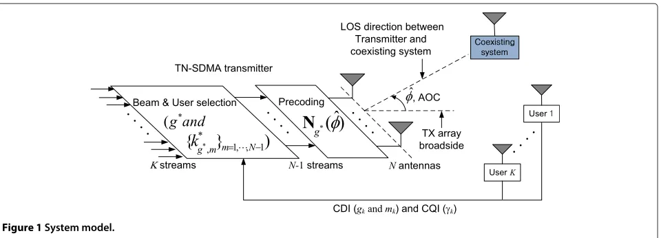
2 TN-SDMA system
Figure 1 illustrates a downlink TN-SDMA system, which consists of a transmitter with N transmit antennas and K users with one receive antenna; operation in the spec-trum owned by other coexisting systems is considered. The system constructs N − 1 orthonormal beams and transmits to N − 1 scheduled users via the precod-ing vector {nm}m=1,...,N−1. Let x∈CN×1 be a transmit
Coexisting system
Figure 1System model.
TN-SDMA and PU2RC under an identical channel model. The received signal for thekth user is given by
yk=hkx+zk =hkN(φ)ˆ s+zk
=hk N−1
m=1
nmsm+zk,
(1)
where hk ∈ C1×N is the channel gain vector with
zero mean unit variance and zk is the complex additive
Gaussian noise with unit variance. The channel gain vec-torhkhas uncorrelated complex Gaussian entries. On the
other hand, the highly correlated channel from a trans-mitter to other coexisting systems is assumed on the basis of the high line-of-sight probability between them. The highly correlated channel facilitates the mitigation of the interference to the coexisting systems by construction of a transmit null at the azimuth direction angle of the coexisting systemsφˆ(we name the angle ‘AOC’). AOCφˆ
is relative to the array broadside, as shown in Figure 1. N(φ)ˆ =[n1. . .nN−1]∈ CN×N−1, and s =[s1. . .sN−1]T,
where(·)T represents the transpose matrix operation, is an uncoded symbol vector that satisfiesE{s2} =P. The total transmit power P is equally allocated overN −1 scheduled users. TheN − 1 precoding vectors (beams) are selected within the TN-SDMA codebook N = {Ng(φ)ˆ }g=1,...,Gwith a sizeM=G(N−1), which consists
ofGorthonormal matricesNg(φ)ˆ ∈ CN×N−1. The beam
and user selection algorithm is described in Section 2.2.
2.1 Systematic codebook
In this section, we briefly review the design of the TN-SDMA codebookN presented in [22,23] and its char-acteristic. Furthermore, we newly derive the exact value of the common null points that the codebook forms. Our design objective is to construct a codebookN that satis-fies two constraints: (1) construction of a transmit null at AOCφˆand (2) orthogonal beamforming. The transmitter obtains AOC by adopting a popular spatial-spectrum
estimation direction-finding method [26,27] or from a database with information concerning the AOC. The AOC is then sent to all K users via a downlink control channel.
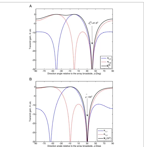
The main steps of the codebook design are outlined in Algorithm 1. We first notice a DFT matrix since it meets the second constraint and notably its column-reduced form constructs a transmit null at a certain direction angle
φ relative to the array broadside (see Figure 2a), which is further expected to satisfy the first constraint using null steering from φ to φˆ (see Figure 2b). Specifically, we introduceGsets of the DFT matrixE= {Eg}g=1,...,G,
where the mth precoding (column) vector of matrix Eg∈CN×Nis [28]
eg,m=
1
√ N
1ej2
π
N
g−1
G +m−1
· · ·ej2
π
N(N−1)
g−1
G +m−1
T
,
m=1,. . .,N.
(2)
This means that the codebook size ofEisM=GN.
Algorithm 1TN-SDMA codebook design algorithm STEP 1: Set up
Number of transmit antennasN, Number of precoding matricesG, Codebook sizeM=G(N−1),
Direction angle of the coexisting systemφ
STEP 2: Initializeg=1 STEP 3: Whileg≤Gdo
STEP 4: ConstructN×NDFT matrixEgusing (2).
STEP 5: ConstructN×(N−1)matrixE(gn)that is
nth -column-reduced matrix ofEg.
STEP 6: Calculate common null pointsφg(n)of the matrixE(gn)using (7).
STEP 7: ConstructN×(N−1)matrixN(gn)using φg(n)andφas in (8),
-90 -70 -50 -30 -10 10 30 50 70 90 -30
-25 -20 -15 -10 -5 0
Direction angle relative to the array broadside, (Deg)
Transmit gain,
(d
B
)
=41.8o
-90 -70 -50 -30 -10 10 30 50 70 90 -30
-25 -20 -15 -10 -5 0
Direction angle relative to the array broadside, (Deg)
Transmit gain,
(d
B
)
B
A
Figure 2Transmit gain.(a)A column-reduced DFT matrixE(13)and its column vectorse1,1,e1,2, and(b)the desired precoding matrixN1(30°) and its column vectorsn1,1,n1,2. We assume the number of precoding matricesG=2, the number of transmit antennasN=3, andλd=0.5.
Next, we constructE(gn) ∈CN×N−1as then
th-column-reduced matrix of Eg; then, each column vector in E(gn)
forms a transmit null in the same directionφ(gn)(named ‘common null point’), which is shown in the following equation:
(E(gn),φg(n)) N
m=1, m=n
|eTg,mv(φg(n))|2=0, (3)
where (M,φ)indicates the transmit power gain of the precoding (beamforming) matrix Mat a direction angle
φ. When considering uniform linear antenna arrays at the transmitter with spacings ofd, the array steering vector v(φ)atφis given by
v(φ)= √1
N
1ej2πdλsinφ· · ·ej2π (N−1)dλsinφ
T
whereλis the wavelength of carrier signal. From the for-mula of the sum of a geometric series, (3) is rewritten as
N
Thus, we obtain the following condition:
2π
where c is any integer except multiples ofN. Figure 2a shows an example of the transmit gain ofE(3)1 with a com-mon null pointφ1(3) =41.8°. From here on, we omit the
maintains the orthogonal beamforming in the following proposition, which is also presented in [22,23].
Proposition 1.The following precoding matrix Ng(φ)ˆ
forms a transmit null at φˆ and satisfies the orthogonal beamforming constraints:
Proof.We consider a linear transformation Ng(φ)ˆ =
Rg(φ)ˆ Eg(n), where the Rg(φ)ˆ must be a unitary matrix
to satisfy the orthogonal beamforming constraints N†g(φ)ˆ Ng(φ)ˆ = I. We thus assume a simple unitary inition of transmit gain in (3) and the assumption that Rg(φ)ˆ is a diagonal matrix.(b) is obtained by using the
addition formula of trigonometric functions. Plugging in rk+1=e−jk(ψ+ν(cos(φ−φˆ g)−1))gives
The method ensures low complexity owing to the sim-ple matrix product. Note thatRgpreserves orthogonality
in contrast with conventional null steering [12]. The code-book size ofN = {Ng(φ)ˆ }g=1,...,GisM=G(N−1)=2B,
and each user feeds backBbits quantization of the chan-nel. Figure 2b shows an example of the transmit power gain of N1(30°) where a transmit null at φ1(3) =41.8° is
shifted to AOCφˆ=30°.
2.2 Beam and user selection with limited feedback
We assume that the kth user perfectly knows the receive channel state information (CSI)hk and the
[18,21,25]. On the CSI, thekth user chooses a precoding vector (beam) from the codebookN as follows:
ngk,mk =arg max
ng,m∈N|hkng,m| 2
=arg max ng,m∈N
cos2(∠(hk,ngk,mk)),
(12)
wherehk=hk/hkis a unit vector representing a
chan-nel direction. This means that the chanchan-nel directionhkis
quantized using the codebookN with sizeM, and vector ngk,mk is the quantized channel direction ofhk that
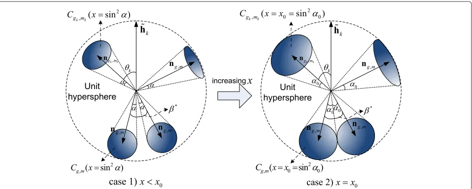
min-imizes angleθk = ∠(hk,ngk,mk), as shown in Figure 3. In
other words, ngk,mk minimizes thequantization error of
the channel directionof thekth user, which is defined as sin2θ
k.
Because the codebook N is known a priori to both the transmitter and the user, only indices gk and mk of
the selected precoding vector (named quantized chan-nel direction information (CDI) index) are sent back to the transmitter, which requires a feedback overhead of B = log2G(N−1)bits, where xis the nearest inte-ger greater than or equal tox. Thekth user also feeds back the channel quality information (CQI), that is, its SINRγk
computed by
γk=
P
N−1hk2cos2θk
1+ NP−1hk2Nj=1,−1j=mk|hkngk,j|2
. (13)
Here, we assume that the SINR is reported to the trans-mitter without quantization and is invariable during beam and user selection (i.e., no CQI delay) as [18,21,25] to investigate the effects of the quantized channel shape on the sum throughput.
We now modify (13) for the theoretical throughput anal-ysis in the next section. We first denote dgk as a unit
vector orthogonal to the (N − 1)-dimensional hyper-plane that the orthonormal basis {ngk,j}j=1,...,N−1 spans.
Set{ngk,1,. . .,ngk,N−1,dgk}forms an orthonormal basis of CN; thus,
N−1
j=1,j=mk
|hkngk,j| 2+ |h
kdgk| 2+ |h
kngk,mk|
2=1, (14)
from which we obtain
N−1
j=1,j=mk
|hkngk,j| 2+|h
kdgk|
2=1−|h kngk,mk|
2=sin2θ k.
(15)
This can be rewritten as
N−1
j=1,j=mk|hkngk,j|2=sin2θk− |hkdgk|2. (16)
Thus, (13) becomes
γk =
P
N−1hk2cos2θk
1+ P
N−1hk2(sin2θk−δ)
, (17)
where 0≤δ= |hkdgk|2≤sin2θk≤1.
According to the CDI indices, allKusers fall intoM= G(N−1)groups defined by
Sg,m= {1≤k≤K|gk=g,mk =m},
1≤g≤G, 1≤m≤N−1. (18)
For each group, the BS selects at most one user with the highest CQI among |Sg,m| users. The selected
Figure 3Channel direction quantizers,ng,mandngk,mk∈N, channel directionhk, and its quantized channel directionngk,mk.The blue surfaces, includingngk,mkandng,m, on the unit hypersphere describe the corresponding spherical caps,Cgk,mk(sin2α)andCg,m(sin2α). Their areas are the same. Here, the quantization error of channel direction, sin2θ
user is indexed as kg∗,m=arg maxk∈Sg,mγk, and his
CQI is
γg∗,m= max
k∈Sg,m
γk. (19)
Thus, the maximum instantaneous sum throughput of thegth precoding matrixNgis estimated as
Finally, among G precoding matrices, the transmitter selects the matrixNg∗ that maximizes the instantaneous
sum throughput in (20) as follows:
This means that the N − 1 precoding vectors {ng∗,m}m=1,...,N−1in theg∗th precoding matrix are used for
simultaneous transmission of their associated users whose indices are {kg∗∗,m}m=1,...,N−1. Thus, the beams for other
user’s transmission remain unaffected by this beam and user selection, and the transmitter exactly predicts SINRs of the users. From (17), (19), and (21), the ergodic sum throughput of TN-SDMA is given by
TN=E
In this section, we analyze the sum throughput of TN-SDMA. We first present preliminary calculations for the throughput analysis, on which the throughput loss of TN-SDMA relative to PU2RC is derived.
3.1 Preliminary calculations
As defined in Section 2.2, the quantization error of the kth user’s channel direction is sin2θk, θk =∠(hk,ngk,mk),
wherehk and ngk,mk ∈ N, respectively, are the
origi-nal and quantized channel directions of thekth user. The quantization error of the codebook composed of mul-tiple unitary matrices is well studied in [21]. Whereas each unitary precoding matrix is independently and ran-domly generated in [21], TN-SDMA employs the precod-ing matrices designed systematically. Therefore, we get a different approach and result from those of [21].
Lemma 1.Given a codebookN with a size M, the com-plementary cumulative distribution function (CCDF) of sin2θ
Proof.See Appendix 1.
Note that because of the deterministic generation of TN-SDMA codebook, Lemma 1 results in different CCDF compared to random codebooks [21,24,25].
Lemma 2.Given a codebookN with size M, the expec-tation of the logarithm of the minimum quantization error is bounded as
Proof.See Appendix 2.
Note that in the proof of Lemma 2, we propose a tighter lower boundKk=11k ≥logK+ηthan the bound
K
k=11k ≥ logK used in the proof of Lemma 3 in
[25], which subsequently results in the tighter bound in Theorem 2.
3.2 Main results
In TN-SDMA, a portion of the spatial degrees of free-dom is dedicated to interference mitigation, and the rest is used for SDMA. This yields a throughput loss of TN-SDMA relative to PU2RC that uses codebookE given in (2) and scheduling described in Section 2.2, which exploits all spatial degrees of freedom to send data streams. We define the throughput loss LT as LT TE − TN, where the ergodic sum throughput of PU2RC is given by [21]
TE andTN are assumed to have the same codebook size, M, i.e., the same number of feedback bits,B= log2M; thus, their numbers of precoding matrices (GE = MN for
PU2RC andG
N = NM−1 for TN-SDMA) are not equal.
Theorem 1. In the normal-SNR regime, the throughput loss relative to PU2RC for large K has an upper bound of
LT ≤log logK+logP+log
1 N
N−1 N
N−1
. (26)
Proof. See Appendix 3.
In (26), logN1NN−1N−1is a decreasing function of the number of transmit antennas N. Therefore, Theorem 1 states that the throughput loss decreases with an increase in N. This is because the ratio of the number of data streams in TN-SDMA to PU2RC, N−1
N , increases to 1 as
N increases. Theorem 1 also shows that a higher SNRP causes an increase in the throughput loss. This can be explained by the fact that PU2RC sends one more data stream than TN-SDMA, and the throughput of the addi-tional data stream increases withP. For lowP, the upper bound of the throughput loss is derived analogously as the following corollary.
Corollary 1.In the noise-limited or low-SNR regime, the throughput loss relative to PU2RC for large K has an upper bound of
LT≤Nlog
1+P N logK
−(N−1)log
1+ P
N−1logK
.
(27)
Note that the throughput loss is still an increasing func-tion of P.
Proof. See the last paragraph of Appendix 3.
The interference dominates over the noise as P increases. For the interference-limited regime, through-puts (22) and (25) are rewritten as
RN =E
max
1≤g≤G N−1
m=1
log
max
k∈Sg,m
1−δ
sin2θ k−δ
,
RE =E
max
1≤g≤G N
m=1
log
max
k∈Sg,m
1 sin2θk
.
(28)
The throughput loss of the interference-limited system is given by the following theorem.
Theorem 2. In the interference-limited or high-SNR regime, the throughput loss relative to PU2RC for codebook size M and large K has an upper bound of
LT ≤
logK+logM
N−1 −η, (29)
whereη=0.5772. . .denotes Euler’s constant.
Proof. See Appendix 4.
Theorem 2 states that the throughput loss eventually converges to an upper limit as SNR P increases, while the throughput loss increases with a codebook sizeM(or the number of feedback bits). This conclusion, in contrast with Theorem 1, is because at highPboth the throughput of TN-SDMA and PU2RC in (28) depend on the quanti-zation error sin2θk(which is dependent onM) but notP. We also note that the throughput loss decreases with an increase inN, as shown in Theorem 1.
Theorems 1 and 2 are obtained for TN-SDMA and PU2RC using the same number of feedback bits, which always causes a throughput loss in TN-SDMA relative to PU2RC. Clearly, more feedback bits for TN-SDMA than PU2RC yield zero throughput loss. We quantify how many feedback bits are required for the zero throughput loss of TN-SDMA in the interference-limited or high-SNR regime. We let ME and MN denote the codebook sizes
of PU2RC and TN-SDMA, respectively. They are given asME = GEN andMN = GN(N −1), where GE and
GNare the numbers of precoding matrices in PU2RC and
TN-SDMA, respectively. The numbers of feedback bits are then given asBE = log2GEN(PU2RC) andBN =
log2GN(N−1)(TN-SDMA).
Theorem 3. In the interference-limited or high-SNR regime, the throughput of PU2RC with BE = log2GEN
feedback bits is achieved by TN-SDMA with BN feedback bits, where
BN =
N N−1BE+
1
N−1log2K−c
. (30)
and c=ηlog2e=0.8327. . ..
Proof. See Appendix 5.
Several examples of Theorem 3 are plotted in Figure 4. The figure shows the number of feedback bits in PU2RC
and the corresponding number of feedback bits in TN-SDMA required to achieve the throughput of PU2RC, for
a given number of transmit antennas,N, and the num-ber of precoding matrices, GE = 2 and 4. For a given
GE, the number of feedback bits in PU2RC increases
2 4 6 8 10 12 14 16 18 20 2
4 6 8 10 12 14 16
Number of transmit antennas, N
Num
b
er of feedback bits
PU2RC, GE =2
TN-SDMA, GE =2
PU2RC, GE =4
TN-SDMA, GE =4
Figure 4Number of feedback bits in PU2RC (B
E) and corresponding required number of feedback bits in TN-SDMA.They are plotted for the number of precoding matrices in PU2RC,G
E=2 and 4.
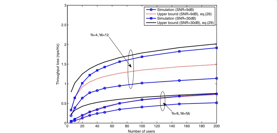
4 Numerical results
Figure 5 shows both the upper bound and the simu-lation results of throughput loss versus the number of usersK for four and eight transmit antennas. The simu-lation confirms the analytical bound; further, the bound is close to the simulation results at largerN. As noted in Theorems 1 and 2, increasingNdecreases the throughput loss. The throughput loss decreases with K, confirming
that TN-SDMA is preferable in a real (i.e., small number of users) environment. The decrease in the throughput loss for smallKis attributed to the fact that PU2RC sends one more data stream than TN-SDMA, and the throughput of the additional data stream decreases with K, which reduces multiuser diversity gain.
Figure 6 presents the throughput loss versus SNR for a system withK = 1, 000. The upper bound for normal
0 20 40 60 80 100 120 140 160 180 200
0 0.5 1 1.5 2 2.5 3
Number of users
Thr
oughput
l
o
ss (
nps/
Hz)
Simulation (SNR=9dB) Upper bound (SNR=9dB), eq.(26) Simulation (SNR=30dB) Upper bound (SNR=30dB), eq.(29)
N=8, M=56 N=4, M=12
0 5 10 15 20 25 30 35 40 0
1 2 3
SNR (dB)
Throughput loss (nps/Hz)
Simulation
Upper bound (normal SNR), eq. (26) Upper bound (high SNR), eq. (29) Upper bound (low SNR), eq. (27)
Figure 6Throughput lossLTversus average SNRPforM=12,N=4, andK=1, 000.
SNR is less than the simulation curve for SNR less than approximately 5 dB. As explained in Corollary 1, the inac-curacy implies that the assumptions NP logK 1 in (47) andNP−1logK 1 in (49) are no longer valid in the low-SNR region. We also find that larger low-SNR increases the throughput loss, as stated in Theorem 2.
Figure 7 plots the sum throughput of TN-SDMA and PU2RC versus the number of usersK. For a givenN, we observe an identical rate of increase in the sum through-put of TN-SDMA and PU2RC, which indicates that the two techniques provide the same multiuser diversity gain. In the scheduling algorithm presented in Section 2.2, each
0 100 200 300 400 500 600 700 800 900 1000
0 1 2 3 4 5 6 7 8
Number of users
Thr
o
ughput
(
nps/
Hz)
PU2RC, N=4, M=12 TN-SDMA, N=4, M=12 PU2RC, N=8, M=56 TN-SDMA, N=8, M=56
user selectsN−1 groups amongM= G(N−1)groups defined in (18), and the size of each group is smaller for higherNor smallerK. Such size reduction decreases multiuser diversity gain, which results in more transmit antennasNyielding lower throughput for a small number of users as shown in Figure 7.
From the above results, it is found that the upper bounds in Theorems 1 and 2 provide the relation for the throughput loss with P, N, and K accurately. In addition, the results indicate that the throughput loss of TN-SDMA relative to PU2RC is smaller at larger N, lower P, or smaller K. It should be noted that although TN-SDMA always has a lower throughput as compared to PU2RC in the non-coexistence scenario, it offers an opportunity for reusing the spectrum already allocated to coexisting systems. Consequently, when a gain of data rate (in bps) due to such a larger bandwidth transmis-sion is superior to a loss of data rate relative to PU2RC,
TN-SDMA will provide higher data rate than PU2RC
does.
5 Conclusions
We have derived theoretical upper bounds of the through-put loss of TN-SDMA relative to PU2RC. On the basis of the bounds, we also quantify the number of feedback bits of TN-SDMA required to achieve the throughput of PU2RC. We find the resulting design fundamentals as fol-lows. First, in terms of minimizing the throughput loss, TN-SDMA is better for point-to-multipoint communica-tion with more transmit antennas, fewer receivers (users), lower SNR, or fewer feedback bits. Second, given a fixed number of transmit antennas and users, the throughput is affected by SNR to a greater extent than by the number of feedback bits in the normal (or low)-SNR region and vice versa in the high-SNR region. Therefore, using more feedback bits is recommended to increase the through-put of high-SNR users. Third, adding feedback bits in only single figures is sufficient for TN-SDMA to achieve the throughput of PU2RC in high-SNR or interference-limited networks. Further extension of this approach could include downlink network MIMO with limited feedback that mitigates inter-cell interference by transmitting data through the null space of an inter-cell interference channel matrix.
Endnotes
a Here, the throughput means spectral efficiency which
is numerically expressed in bits per second per hertz or nats per second per hertz (1 nps/Hz = 1.44 bps/Hz).
b We need to note that in spite of the lower spectral
efficiency, TN-SDMA is desirable in order to keep existing systems in operation.
c 3GPP LTE-Advanced base station is designed to
support up to eight antennas.
Appendices
Appendix 1: proof of Lemma 1
For the ith precoding vector ni ∈ N(φ)ˆ , 1 ≤ i = (g−1)(N−1)+m≤ M, we defineA(Ci(x))as the
sur-face area of a spherical capCi(x)on the unit hypersphere,
where the cap is defined asCi(x) = {h : 1− |h·ni|2 ≤
x}, 0 ≤ x ≤ 1. From [29, Lemma 4], the surface area is given asA(Ci(x)) = 2π
NxN−1
(N−1)! , andA(Ci(1))is the entire
surface area of the hypersphere. Then the CCDF of sin2θ k
is given as
P[sin2θk≥x](=a)1−A(
M
i=1Ci(x))
A(Ci(1))
(b)
=1−
M
i=1A(Ci(x))
A(Ci(1))
=1−MxN−1, 0≤x≤x0,
(31)
where(a)follows from that when sin2θk ≥x, the channel directionhkis outside all the spherical caps{Ci(x)}i=1,...,M,
as shown in Figure 3.(b) holds forxthat is less than or equal to the maximum valuex0 where all the spherical
caps do not overlap, as shown in Figure 3. To calculatex0,
we first define the minimum angle between the precoding vectors{ni}i=1,...,Kgiven as
β∗= min
1≤i≤j≤M∠(ni,nj). (32)
We then derivex0as follows:
x0=sin2α0
(a)
=sin2β
∗
2 = 1
2(1−cosβ
∗)
(b)
= 1 2
1−cos
min
1≤i≤j≤M∠(ni,nj)
= 1 2
1− max
1≤i≤j≤Mcos
∠(ni,nj)
= 1 2
1− max
1≤i≤j≤M|n
†
i ·nj|
,
(33)
where(a) follows fromα0 = β ∗
2 (see the right figure of
Figure 3) and(b)follows from (32).
Appendix 2: proof of Lemma 2
DefineX=min1≤k≤Ksin2θkandX=M 1
N−1X; then from
(23), the CCDF ofXis
PX≥x=
P
sin2θk≥ 1
M
1 N−1
x
K
=1−xN−1K, 0≤x≤x1=M 1 N−1x0.
We then define a probability ofX
P1(x)P[X≤e−x]=1−1−e−x(N−1)K, x≥ −logx1.
(35)
Since a CDF is a monotonically increasing function,
P1(x)≥P1(x= −logx1)
=1−1−x1N−1K, x≤ −logx1.
(36)
We denoteZ as the minimum ofK independent beta
(N−1, 1)random variables, and define a probability ofZ [24, Lemma 1]:
P2(z)P[Z≤e−z]=1−
1−e−z(N−1)
K
, z≥0.
(37)
ComparingP1withP2, we obtainP1(x)=P2(z)forz=
x∈[−logx1,∞). We thus obtain the following inequality
(b)from (36):
E[−logX](=a)
−logx1
0
P1(x)dx+
∞
−logx1
P1(x)dx
(b)
≥((1−xN1−1)K−1)logx1+
∞
−logx1 P2(z)dz,
(38)
E[−logZ](=c)
−logx1
0
P2(z)dz+
∞
−logx1
P2(z)dz
(d)
≤ −logx1+
∞
−logx1
P2(z)dz, (39)
where(a)and(c)follow fromE[Y]=0∞P[Y >y]dyand
(d)follows fromP2≤1. From (38) and (39), we have
E[−logX]−E[−logZ]≥(1−xN1−1)Klogx1. (40)
FromX =MN−11 Xandx1 = MN−11 x0, (40) is rewritten
as
E[−logX]≥ logM
N−1+E[−logZ]+(1−Mx
N−1 0 )K
×log(MN−1x0)
(a)
= logM N−1+
1 N−1
K
k=1
1
k+(1−Mx
N−1 0 )K
×log(MN−1x0),
(41)
where(a)follows from [25, Lemma 3]:
E[−logZ]= 1 N−1
K
k=1
1
k. (42)
From logK=1K 1tdt, we obtain
logK< K
k=1
1
k <logK+1. (43)
Furthermore, since Kk=11k − logK is a monotoni-cally decreasing function of K and limK→∞Kk=11k−
logK=η, where η denotes Euler’s constant [30], we obtain
logK+η≤ K
k=1
1
k ≤logK+1. (44)
Combining (42) with (44) gives
logK+η
N−1 ≤E[−logZ]≤
logK+1
N−1 . (45)
Combining the left inequality in (45) with (41), we obtain the desired lower bound.
Next, the right inequality in (45) results in the following inequality(a):
E−logX− logM N−1 =E
−logX
≤E−logX0≤X≤x1=x0M 1 N−1
=E−logZ 0≤Z≤x0M 1 N−1
≤ E
−logZ
P0≤Z≤x0M 1 N−1
(a)
≤ 1+logK
(N−1)(1−ξ ),
whereξ = 1−P[0 ≤ Z ≤ x0M This gives the desired upper bound.
Appendix 3: proof of Theorem 1 and Corollary 1
The upper bound for TE in (25) is given in a similar manner to Theorem 1 in [16]:
TE =E
We next derive the lower bound forRN. From (22), the lower bound forRN is given as
and (b) is given from the last inequality in the proof
logK. From (48) and (50), we obtain the desired result in Theorem 1.
We now prove Corollary 1. In spite of a large value ofK, both assumptionsNP logK1 in (49) are no longer valid for lowP. Therefore, (47) and (49) are written as
TE ≤Nlog
from which we obtain the desired result in Corollary 1.
Appendix 4: proof of Theorem 2
From (28), the upper bound forTEis given as
TE =E
where(a)is obtained from the upper bound in Lemma 2 and(b)is given on largeKassumption.
2 is the maximum
dis-tance of the codebook. ComparingUg,mwithSg,min (22) δ < 1. The number of users contained in the set
Ug,m satisfies the following inequality [21, Lemma 1]: P|Ug,m| ≥x2N−1K−1 ≥1−K−1, where we use the
sub-stitution ofU =K,A=x2N−1, andτ1=τ2=K−1. Thus,
(55) is rewritten as
TN ≥(N−1)E
Applying the lower bound in Lemma 2 to (56), we obtain
TN≥
where(a)follows from the largeKassumption. From (53) and (57), we obtain the desired result.
Appendix 5: proof of Theorem 3
Given the number of antennasN and precoding matrix of PU2RCGE (and TN-SDMAGN), the codebook size is
TN-SDMA). The upper bound ofTEin (53) and the lower bound ofTNin (57) are rewritten as
TE ≤ N N−1
logK+logME
, (58)
TN ≥η+logK+logMN. (59)
The zero upper bound of the throughput loss LT is valid when the two bounds above are the same, i.e., the codebook size of TN-SDMA is
logMN =
N
N−1(logK+logME)−η+logK. (60)
After some algebra, the number of feedback bits of TN-SDMA is given as
BN = log2MN
=
1 N−1log2
(GEN)NK
eη(N−1)
=
N N−1BE+
1
N−1log2K−ηlog2e
. (61)
Obviously, the zero upper bound ofLT is sufficient for the zero throughput loss. Therefore, TN-SDMA withBN feedback bits given in (61) yields zero throughput loss, i.e., achieving the throughput of PU2RC.
Competing interests
The authors declare that they have no competing interests.
Acknowledgements
This research was supported by the Basic Science Research Program through the National Research Foundation of Korea (NRF) funded by the Ministry of Education, Science and Technology (2013R1A1A1005731), and by the Ministry of Science, ICT & Future Planning (MSIP), Korea, in the ICT R&D Program 2013.
Author details
1Department of Electronic Communication Engineering, Korea National
University of Transportation, Chungju 380-702, South Korea.2Department of Electronics and Control Engineering, Hanbat National University, Daejeon 305-719, South Korea.
Received: 26 March 2013 Accepted: 6 November 2013 Published: 20 November 2013
References
1. Cisco, CISCO white paper: Cisco visual networking index: global mobile data traffic forecast update (2013). http://www.cisco.com/en/US/ solutions/collateral/ns341/ns525/ns537/ns705/ns827/white_paper_c11-520862pdf. Accessed 15 Nov 2013
2. L Lu, X Zhou, U Onunkwo, G Li, Ten years of research in spectrum sensing and sharing in cognitive radio. EURASIP J. Wireless Commun. Network.
2012, 28 (2012)
3. J Andrews, H Claussen, M Dohler, S Rangan, M Reed, Femtocells: past, present, and future. IEEE J. Select. Areas Commun.30(3), 497–508 (2012) 4. A Ghosh, N Mangalvedhe, R Ratasuk, B Mondal, M Cudak, E Visotsky, T
Thomas, J Andrews, P Xia, HS Jo, H Dhillon, T Novlan, Heterogeneous cellular networks: from theory to practice. IEEE Commun. Mag.50(6), 54–64 (2012)
5. C Eriksson, T Irnich, P Mustonen, M Ojanen, C Wijting, R Yahi,IST-4-027756 WINNER II D 5.10.1 v1.0, The WINNER Role in the ITU Process Towards IMT-Advanced and Newly Identified Spectrum. (Nokia Siemens Networks, Munich, 2007)
6. D Gesbert, M Kountouris, R Heath, CB Chae, T Salzer, Shifting the MIMO paradigm. IEEE Signal Process. Mag.24(5), 36–46 (2007)
7. S Parkvall, A Furuskar, E Dahlman, Evolution of LTE toward IMT-Advanced. IEEE Commun. Mag.49(2), 84–91 (2011)
8. HS Jo, C Mun, J Moon, JG Yook, Interference mitigation using uplink power control for two-tier femtocell networks. IEEE Trans. Wireless Commun.8(10), 4906–4910 (2009)
9. HS Jo, C Mun, J Moon, JG Yook, Self-optimized coverage coordination in femtocell networks. IEEE Trans. Wireless Commun.9(10), 2977–2982 (2010)
10. TA Weiss, FK Jondral, Spectrum pooling: an innovative strategy for the enhancement of spectrum efficiency. IEEE Commun. Mag.42(3), 8–14 (2004)
11. HS Jo, P Xia, J Andrews, Open, closed, and shared access femtocells in the downlink. EURASIP J. Wireless Commun. Network.2012, 363 (2012) 12. LC Godara, Application of antenna arrays to mobile communications. II.
Beam-forming and direction-of-arrival considerations. Proc. IEEE85, 1195–1245 (1997)
13. T Ohgane, Spectral efficiency improvement by base station antenna pattern control for land mobile cellular system, inIEEE Global
Telecommunications Conference 1993(IEEE Piscataway, 1993), pp. 913–917 14. H Weingarten, Y Steinberg, S Shamai, The capacity region of the Gaussian MIMO broadcast channel, inProceedings of the International Symposium on Information Theory, 2004. ISIT 2004(IEEE Piscataway, 2004), p. 174 15. Q Spencer, A Swindlehurst, M Haardt, Zero-forcing methods for downlink
spatial multiplexing in multiuser MIMO channels. IEEE Trans. Signal Process.52(2), 461–471 (2004)
16. M Sharif, B Hassibi, On the capacity of MIMO broadcast channel with partial side information. IEEE Trans. Inf. Theory51(2), 506–522 (2005) 17. W Choi, A Forenza, J Andrews, R Heath, Opportunistic space-division multiple access with beam selection. IEEE Trans. Commun.55(12), 2371–2380 (2007)
18. T Yoo, N Jindal, A Goldsmith, Multi-antenna downlink channels with limited feedback and user selection. IEEE J Select. Areas Commun.25(7), 1478–1491 (2007)
19. Samsung Electronics,R1-060335 Downlink MIMO for EUTRA. (Samsung Electronics, Suwon, 2006)
20. Third Generation Partnership Project 2,3GPP2 C.S0084-001-0. Physical Layer for Ultra Mobile Broadband (UMB) Air Interface Specification. (3GPP2, Arlington, 2007)
21. K Huang, JG Andrews, RW Heath, Performance of orthogonal beamforming for SDMA with limited feedback. IEEE Trans. Vehicular Technol.58, 152–164 (2009)
22. HS Jo, C Mun, Transmit-nulling SDMA for coexistence with fixed wireless service. J. Korean Inst. Electromagnetic Eng Sci.11, 34–41 (2011) 23. HS Jo, Codebook-based precoding for SDMA-OFDMA with spectrum
sharing. ETRI J.33(6), 831–840 (2011)
24. C Au-Yeung, DJ Love, On the performance of random vector quantization limited feedback beamforming in a MISO system. IEEE Trans. Wireless Commun.6(2), 458–462 (2007)
25. N Jindal, MIMO broadcast channels with finite-rate feedback. IEEE Trans. Inf. Theory52(11), 5045–5060 (2006)
26. JA Fessler, AO Hero, Space-alternating generalized expectation-maximization algorithm. IEEE Trans. Signal Process.42(10), 2664–2677 (1994)
27. P Chevalier, A Ferreol, L Albera, High-resolution direction finding from higher order statistics: the 2q-MUSIC algorithm. IEEE Trans. Signal Process.
54(8), 2986–2997 (2006)
28. BM Hochwald, TJ Richardson, W Sweldens, TL Marzetta, R Urbanke, Systematic design of unitary space-time constellations. IEEE Trans. Inf. Theory46(6), 1962–1973 (2000)
29. KK Mukkavilli, A Sabharwal, E Erkip, B Aazhang, On beamforming with finite rate feedback in multiple-antenna systems. IEEE Trans. Inf. Theory
49(10), 2562–2579 (2003)
30. A Jeffrey, D Zwillinger,Tables of Integrals, Series, and Products. (Academic, San Diego, 2007)
doi:10.1186/1687-1499-2013-270